Setup, Calibration, Coordinate Systems, Pen Swapping, and Head Scratching
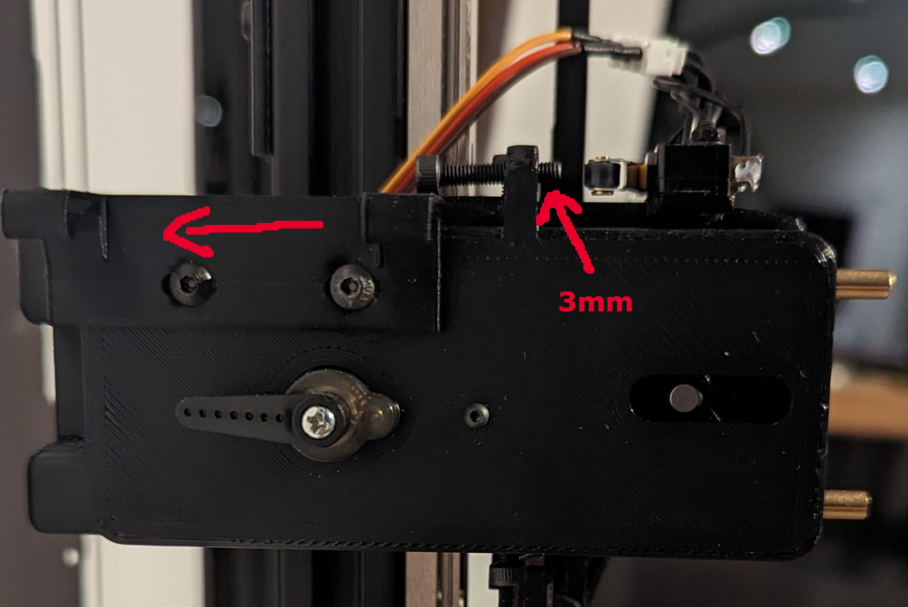
Set the Z-Axis adjustment screw so you have about 3mm showing on the end. Then position the Pen Holder Bracket (part R) so it is all the way down. To do that, loosen the two M3 button head bolts that hold it on and slide it toward the drawing surface as far as it will go, then tighten the bolts. Be sure the bracket sits perfectly flat on the slider’s face, and tighten the button heads so they are all the way in.
Assuming you have tested your switches, motor directions, etc. The first thing to do is to calibrate the x and y steppers.
- Home the machine and make sure you are using millimeters. ($HZ, $HX, $HY, G21)
- Move to Machine Position X67 Y0 and set this as your Work X0 Y0. This will make sure you don’t accidentally crash into any pens that happen to be in the toolbin. FluidNC will remember this offset.
- Make sure the x and y motors move the correct distance and modify the “steps_per_mm:” setting in the X and Y axes sections of the config if necessary. I typically will start at Work X0 Y0, make a small mark on the rail next to the block, move to X500, make a similar mark, move to X600 or so, to get the gantry out of the way, then measure the distance between the marks to make sure it is exactly 500mm. Adjust the X-axis “steps_per_mm:” and repeat as necessary. Then do the same for the Y axis.
- If you decide to get more accurate at a later date (like after you start grabbing pens and drawing on paper), just be aware that those changes may affect the settings you will use regarding toolbin position and pen extraction/insertion.
Now, an explanation of how I set things up. I’m no expert when it comes to GRBL coordinate systems, offsets, g-code, etc. There are several ways to do things and there may be a better way than mine, but here is what I do …
I play in the G54 coordinate system and will frequently use G92 to set temporary work offsets. So, in my future g-code examples, you might see a lot of G54, G92 and G92.1 codes. I also $H a lot.
I will also mention that I have a custom WebUI for FluidNC that does a bit of post-processing of g-code files that get created with other software like Sandify, GRBL Plotter, etc. That isn’t something that is necessary to make this work (you can manually tweak the g-code and upload it via the FluidNC WebUI), but I wanted to eliminate that step so a 5-year-old can select a picture and have the machine draw it. Many g-code processors will insert tool change commands when a new pen type/color is needed (T01, T02, etc.) and instead of replacing those manually with the necessary pen extraction/insertion code, it is nice to have a post-processor do it automatically before sending the file to FluidNC. I will explain my UI in a separate thread. Right now, we need to figure out how to grab pens…
The big picture: The Work coordinates are offset +67mm in the X axis from the Machine coordinates (you should have just set that). Machine and Work coords are the same in the Y and Z axes (no offset). The Y position of the toolbin is up to you. I position it so the uppermost pen (Pen1) is at Y710. When making tool (pen) changes I always go to Absolute Machine coordinates X67 Y710, then switch to relative coordinates to grab the appropriate pen, then switch back to Absolute Work coordinates to continue with the plot. I do pretty much the same thing when inserting a pen back into the bin. If you want to position the tool bin higher or lower, then make a corresponding adjustment to the “710” in my examples. Horizontally, the pens are located at Machine position X1. When a pen is in the holder and the plotter is at Z0, the pen tip will be 1 to 1.5 mm above the paper surface. The lowest position possible for the pen carriage is Z-4. That is where it “bottoms out”. So, assuming Z-1.5 equates to where the pen contacts the paper… if Z is set to -4 in the g-code, the pen can still travel another -2.5mm (if the drawing surface is warped) and still contact the paper (because it is being held on the paper by the spring). So, there is a little leeway when it comes to a non-perfect back board. Typically, I set the height for drawing at Z-3 and the height for repositioning at Z2.
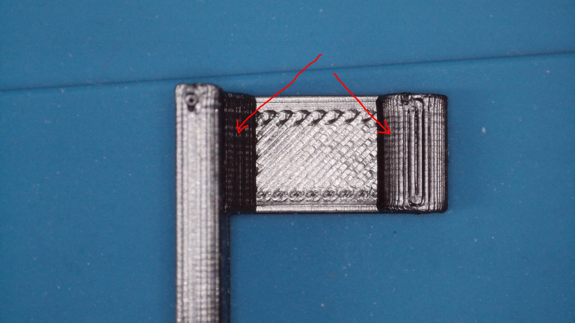
Now, let’s teach it how to hold a pen. Move the pen carriage to a place it will be easy to access. Something like X400 Y700. Then send it the command M3S0 and then M3S100. You should see and/or hear the servo move. If it doesn’t, check your wiring and connections. After the M3S100 command is sent, the servo arm should be in the 6 o’clock position (if on a table) or 9 o’clock if on a wall. In other word, the servo arm should be pointing directly at the drawing surface. Refer to pic below. If it looks like that, then it’s an absolute miracle that you happened to attach the servo arm exactly where it should be.
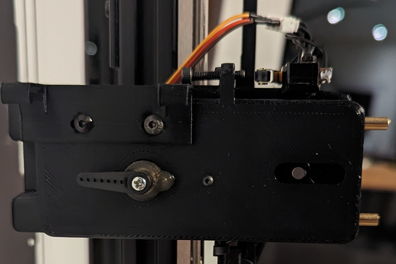
If necessary, remove and re-attach the arm so it is as close to the above picture as possible. The position of the arm after you send command M3S0 should look like the picture below.
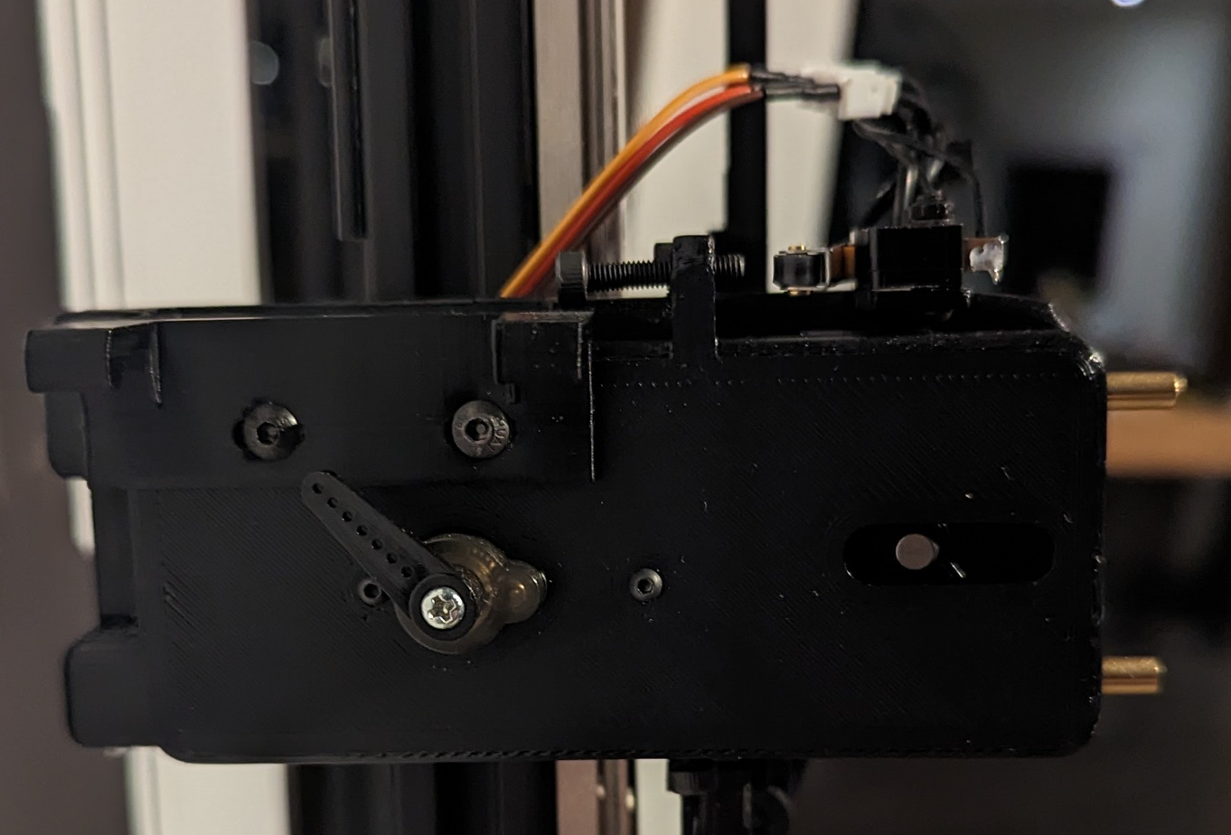
There are two settings in the BESC section of the config called min_pulse_us and max_pulse_us. The max pulse setting will affect the position in the first pic and the min pulse will affect the position in the second pic. Set a lower value to move clockwise, higher to move anticlockwise. To start, just try to get them in the ballpark of the above pics.
The next step is easier with two people, but you can do it yourself if you open the fluidNC UI on your phone or tablet so that you can enter and send a command with one hand while holding the pen with the other. Grab a pen (I recommend a Pigma Micron) and slide it into one of the Micron pen holders you printed out. There will be an M on the holder. Make sure it is slid all the way in. Send an $HZ command and after it homes, send Z8 to lift the slider to a comfortable height. Send M3S100 to “open” the claw. While holding the pen in position (see pic below), send M3S0 to close it.
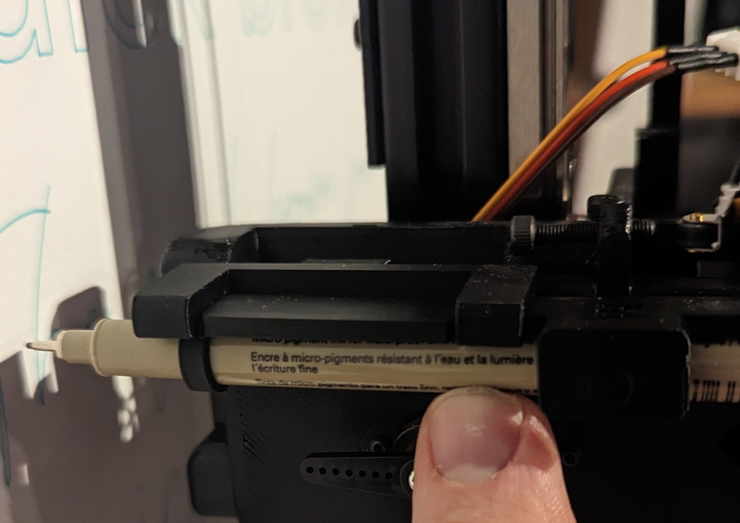
If the pen can move around after the M3S0 command (too loose), then you need to decrease the value of min_pulse_us. If the servo is squealing (too tight), then you will need to increase the value. Repeat the process as necessary. I think that changes to these settings do not take effect until fluidNC is rebooted, so beware of that. A slight noise from the servo is better than a loose pen. Note that the min_pulse can’t be set below 500, so you may need to position the servo arm to the next clockwise detent if it can’t grasp a pen properly.
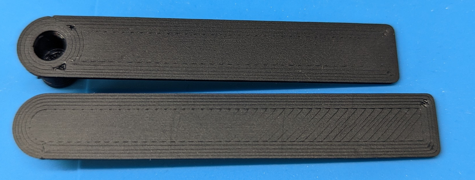
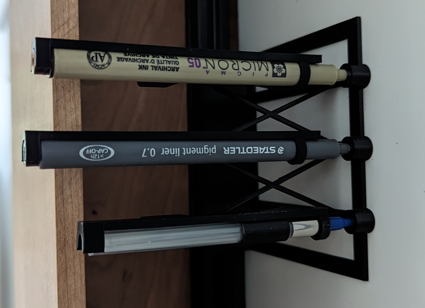
Now is a good time to make sure you have magnets in the toolbin as well as the pen brackets. Make sure to be consistent with polarity. The magnets can be a pain to insert because they need to go in perfectly lined up with the recess and they are very small. Be creative. I mark one side of the magnet with a red sharpie to keep track of polarity and use small pliers to get them in. I included the pic below to show the different pens and to show the position of the sleeve on the Uni-ball PowerTank (lowest pen). Note that Uni-ball PowerTank has two versions, a retractable pen and a capped pen. This bracket fits the retractable style refills. Note: That is toolbin version 1 in the pic. If someone wants to make a rack that holds a different number of pens than the uploaded model, I can make the Fusion 360 files available, and you can make your own custom size.
Mount the toolbin in the top half of the left extrusion and keep the bolts loose enough so it can slide. With a pen in the carriage, move it to Machine cords X67 Y710. A height of Z10 should be good to start, but we haven’t adjusted Z yet so make sure the height is high enough so the tip of the pen clears the well as you move it into the holder in the next steps. Jog the pen to Machine X10 (Work X-57) and position the tool bin so the top well is lined up with the pen (you don’t have to be exact just yet). Move the pen in small X increments (don’t change Y) until the tip is perfectly centered over the well. You can adjust Z to move the tip down to get a more exact position if needed. Now slide the toolbin so the top pen well is dead center under the pen tip (Y should still be at 710) and tighten the bolts that hold it on the extrusion. Y is now calibrated. With the pen tip centered over the well, the X position should be around Machine X1. That adjustment is made by adjusting the Machine home, which is accomplished by using the adjustment screw on the X-Axis Stop Bracket (Mod 1). When re-homing X after you change the X-Axis adjustment screw, make sure the pen carriage is not lined up with the tool bin. Otherwise, it will crash into any pens that are in the rack.
NOTE: Once you understand how the pen exchange works, you will realize that there are several ways to calibrate the X axis origin. I am just giving you a reference point to start with, so we are doing it mechanically with the adjustment screw. If that’s not working for you, you can also adjust the values in the pen swapping gcode, or adjust the X-Axes Motor Pulloff values in the config.yaml.
Okay… So at this point, you should be able to position a pen directly over the well in pen position 1 by sending the following commands (send each line in its entirety, i.e. don’t send G90, then G53, then X67 …, send G90 G53 X67 Y710 all together)
$H (home the machine)
G90 G53 X67 Y710 (move to the toolbin entry point)
Z10 (Move the pen tip up so it clears the well)
M3S100 (open the claw and place and a pen in the holder)
M3S0 (close the claw)
G53 X1 (move to pen position 1)
All good? If not, scratch your head, post a question if you need help, do what you need to do and come back here when it works.
Let’s adjust the Z…
First, release the pen (M3S100 while holding it) and remove it from the claw. Move the carriage out of the way and place the pen in the top position in the tool bin.
In the next step, we’re gonna switch to relative coordinates to make things easier, so be aware of that. Home the machine if you think it needs it, then send the following commands. This will position the bracket on the pen carriage just over pen 1.
G90 G53 X67 Y710 (move to the toolbin entry point)
Z1 (this is the height at which the claw grabs the pens)
G91 (switch to relative)
Y4 (move 4mm up)
X-66 (move 66mm to the left)
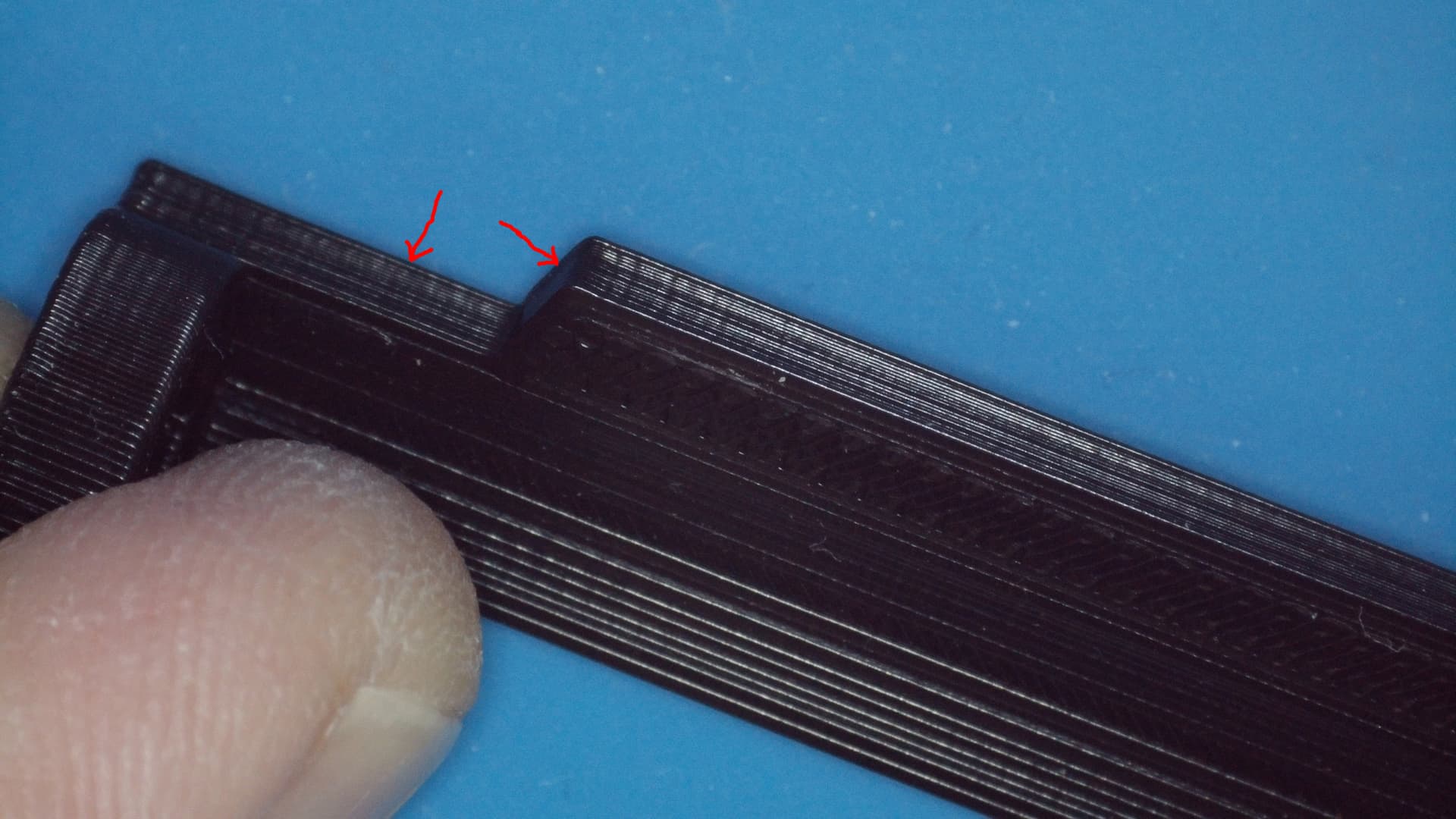
Now, take a look at the height of the Pen Holder Bracket (part R) relative to the Pen Bracket (Part U). We are going to move down on the Y axis a total of 4mm and the Pen Holder Bracket should be able to do this without striking the Pen Bracket. A slight rub is fine, but it shouldn’t dislodge the pen from the toolbin. Send Y-1, then Y-1 (a total of 4 times) and see what you have. If you can send Y-1 four times without significantly moving the pen, your Z height is good. You might need to back out of the tool bin, turn the Z axis adjustment bolt to make an adjustment, send an $HZ to rehome, then run through the above commands starting at G90…
Make all the necessary adjustments so you can run the following:
G90 G53 X67 Y710 (move to the toolbin entry point)
Z1 (this is the height at which the claw grabs the pens)
G91 (switch to relative)
Y4 (move 4mm up)
X-66 (move 66mm to the left)
Y-4 (move down 4mm so the claw is around the pen)
M3S0 (grab the pen with the servo)
Z10 (lift the pen out of the well)
X66 (move back to the toolbin entry point)
Z-5.5 (move the pen to a neutral height)
G90 (switch back to absolute coords)
To put the pen back into the tool bin:
G90 G53 X67 Y710 (move to the toolbin entry point)
Z10.5 (lift the pen so it clears the well)
G91 (switch to relative)
X-66 (move the pen into position)
Z-9.5 (lower the pen into the well)
M3S100 (release the claw)
Y4 (move the claw away from the pen)
X66 (move back to the entry point X)
Y-4 (move back to the entry point Y)
Z4.5 (neutral height for the slider)
G90 (switch back to absolute coords)
Smooth sailing from here….
I need a drink. You do too. Next post… pen macros and post g-code processing to tie everything together.
Cheers.