Noo, i mean a table like your dining table, with glass over it!!! I know the lr4 can do it, that is in the garage!
1 Like
You have your CNC’s out in the garage??? Mine are way to pretty and clean for that ![]()
5 Likes
Yes, sorry! ![]()
![]()
1 Like
How about using yours for a change instead of just inventing them? Now that you don’t need to cut any more LR3 plates you need something new to cut. ![]()
I have log shaped drink coasters coming out of my ears, I can supply every restaurant and bar in a 100 mile radius. ![]()
Kidding, I have been sketching a few ideas up to make. Back to some fun stuff, not just production is a good change.
2 Likes
Frame and Back Board
Notes:
The size of my original plotter was a result of optimizing available materials. For instance, I decided on ½” MDF for the backboard. The local HD sells these in sheets that are 97” x 49”. (By the way, I apologize in advance for mixing Metric and Imperial units.) Anyways, that gave me a 49”x 49” back board. A width of 49” is perfect if using the 1220mm extrusions that I linked to in the BOM post. Those are actually around 1223mm (48 1/8”) and with a 49” wide back board, there was no need to cut them. That also fits a 36” roll of plotter paper perfectly. The paper is sold in rolls of 36”, 30”, 24” … so depending on what width you want, decrease all the width dimensions by 6” for 30” paper or 12” for 24” paper…
In the photos that I post, the plotter in the wood frame uses 36” paper and the plotter shown without a wood frame uses 30” paper.
Regarding ½” MDF. Maybe not the best choice since it tends to cup a little when you paint/prime it. Probably best to leave it as is, but if you want a white backing, then be sure to prime/paint both sides evenly and the cupping tends to get canceled out. ¾” MDF would probably be better, but there is a weight tradeoff. Whatever you use, the pen holder can tolerate a 2mm difference (maybe 3mm) in surface height (between the lowest point and the highest point). Not much.
So, to sum up…
36” Paper: 49” wide back board, 48.125” horizontal (x-axis) extrusions with 1000mm rails. Print area will be 865mm (34") wide.
30” Paper: 43” wide back board, 42.125” horizontal (x-axis) extrusions with 848mm rails. Print area will be 715mm (28") wide.
…
Print area height with a 1000mm rail will be 920mm (36").
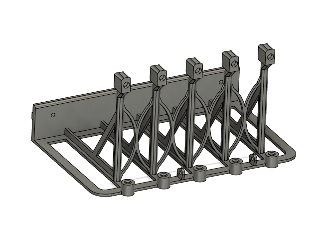
Here are the 3d Parts needed for the frame. The 3d model filenames include description, recommended filament type and the number you will need. You can probably get away with printing everything in PLA with 100% infill if you can’t print ABS. I recommend printing the parts in the orientation shown in the pic. You may need a brim for the chain cradles as there isn’t a lot of first layer contact when they are printed on their side as shown.
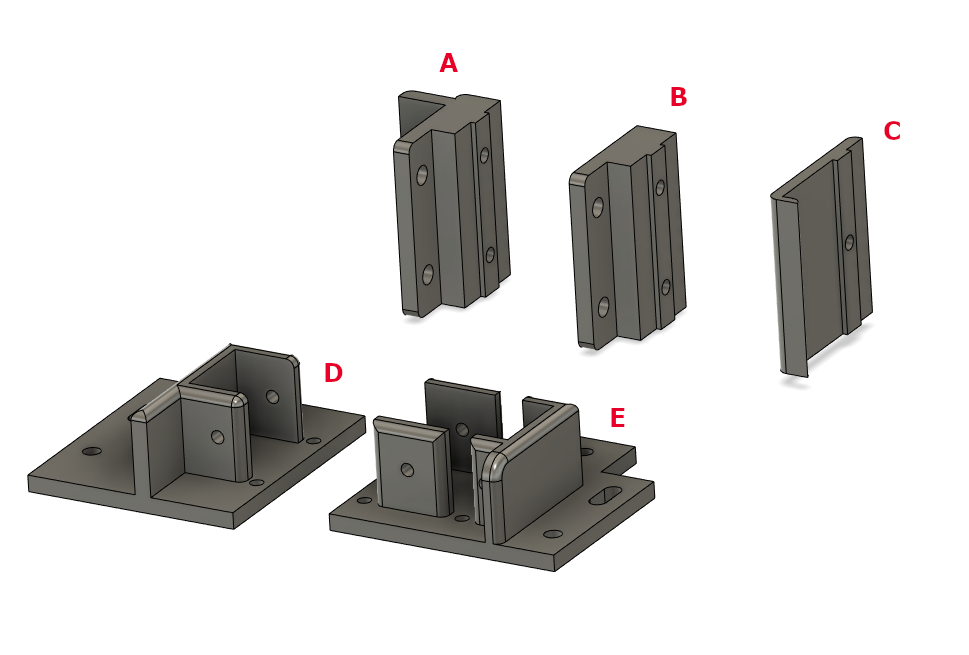
A: Side Mounts (6)
B: Surface Mounts (4)
C: Large Drag Chain Cradles (5)
D: Y-Axis Bottom Truck (1)
E: Y-Axis Top Truck (1)
frame_mount_3dmodels.zip (68.4 KB)
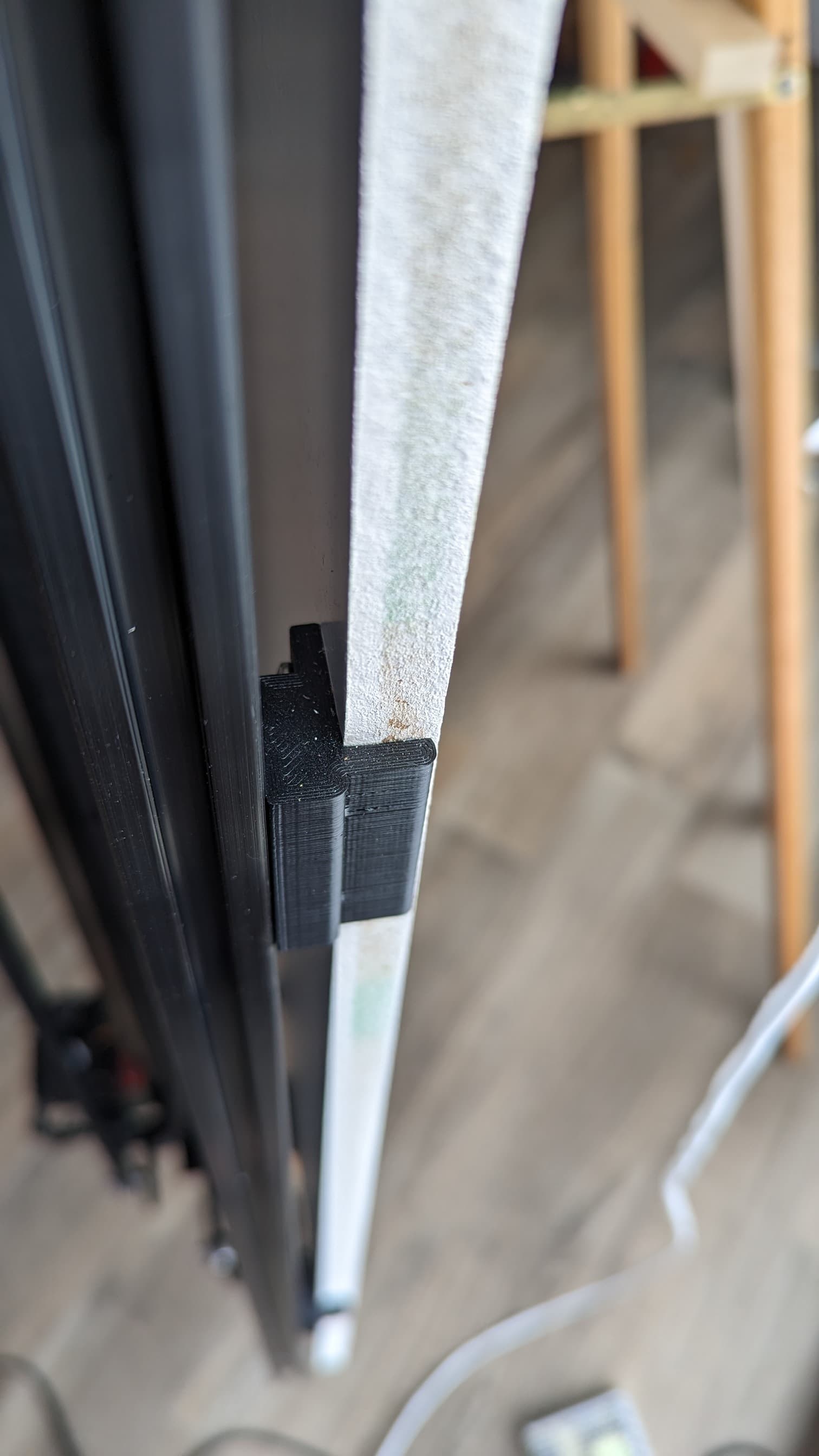
This shows the location of the mounts. The paper needs to fit between the top and bottom frame surface mounts (B). I added 3/8” padding to each end of the paper, so for 36” paper, the horizontal distance between the B mounts is 36 ¾”. If you are not planning on using a roll of paper, then consider printing 2 extra of the B mounts and place them in the center of the top and bottom frame extrusions.
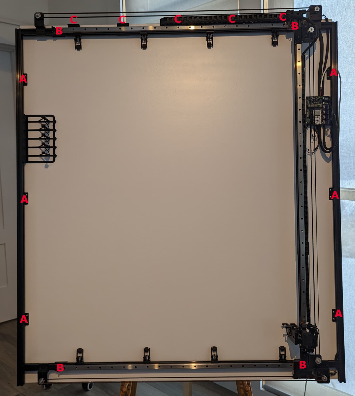
The mounts are attached to the extrusions with M3x12 button heads. I included the large drag chain cradles in this step since they get mounted to the underside of the top horizonal extrusion (with M3x8 button heads) and once the extrusion mounts are attached to the back board, they can’t be accessed with a normal sized allen wrench. The measurements in the second pic above are from the INSIDE of the frame extrusions.
I recommend this order of things:
- Tap both ends of each horizontal frame extrusion to accept an M6 button head for a blind joint.
- Drill the hole in the tops of each vertical (frame sides) extrusion for the blind joints.
- Attach all the mounts and cradles just tight enough so they can slide, but not on their own
- Thread in the M6 button heads for the blind joints enough so the top and bottom horizontal extrusions can slide into the vertical extrusions.
- Set the frame onto the back board
- Cut the Y-Axis extrusion to 46 ½” in order to optimize the length for a 1000mm vertical rail. Technically, you don’t have to shorten the extrusion, but if you leave it at 48", you are just extending the height of the machine without gaining any drawing area since the area is limited by the linear rail.
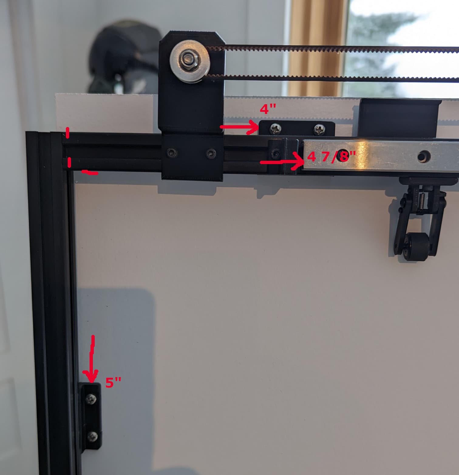
- Attach the top and bottom horizontal rails to the extrusions. The left end of each rail will be 4 7/8” from the INSIDE of the left vertical frame extrusion. You will need to pop in the T-nuts and line them all up with the applicable holes before you start putting in the screws. I put screws in the ends and every 3rd hole, but the more the better I suppose. Don’t crank any of them down until they are all in.
- Attach the top and bottom Y-Axis trucks to the MGN15H rail blocks with M3x10 button heads. The top truck has two holes that are sized to accommodate the M3 brass nuts that are inserted with a soldering iron. It might be easier to do that on the bench before you install the truck.
- Slide the Y-Axis extrusion (that you just cut) into the trucks so there is no space on the top or bottom. They will fit nice and snug. Edit: See the picture and comments in my next post.
- The Y-Axis should now slide back and forth easily. Slide the Y-Axis all the way to the left, square up the frame, then mark where you need to drill the hole for the bottom left blind joint. Repeat with the Y-Axis slid to the right making sure your frame is square each time you move the extrusion.
- Remove the vertical frame extrusions, drill the holes for the blind joints, then reassemble the frame so it is nice and square and the Y-Axis slides back and forth smoothly
- Position all the mounts, remove the frame from the back board and tighten all the mounts securely to the extrusions. The right most chain cradle should be able to slide because the drag chain will eventually be mounted to it and there may need to be a minor adjustment in order for it to fit correctly.
- You can now secure the mounts to the back board with #6x1/2” screws if you need to, although if you don’t have to, it might be better to wait until the end of the assembly in case you need to reposition a mount or drag chain cradle. When you do attach the frame, I recommend pre-drilling, especially if using MDF. And check for square and smooth Y-Axis movement. Again and again…
That’s all for now. My brain hurts.
2 Likes
I thought a bit more detail on the Y-Axis extrusion mount was in order. This pic shows the top end of the extrusion fit snuggly into the top truck. You can slide some t-nuts into position in the extrusion slots and secure the truck to the extrusion with some M3x10 socket heads. Two (one on each side) of the top truck and two on the bottom truck. You will probably want to remove it later when it’s time to install the small drag chain cradles, but that is easily done.
Edit: By the way, I should mention that some of the screw lengths I specify throughout these instructions may be wrong. So… for the extrusion mounts, the screws should ideally be long enough to thread through the entire nut but not so long that it contacts the inside of the extrusion. The block mounts should be as long as possible without bottoming out.
1 Like
Upper and Lower X-Axis Assemblies
3d Parts
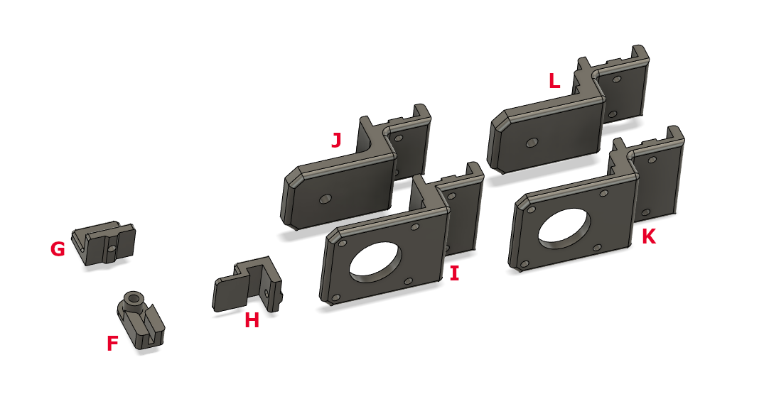
F: Timing Belt Mount (6 total) (2 will be used later on the Y-Axis)
G: Stop Bracket (4 total) (1 will be used later on the Y-Axis)
H: X-Axis Stop Bracket for Homing Switch (1)
I: X-Axis Lower Motor Mount (1)
J: X-Axis Lower Idler Mount (1)
K: X-Axis Upper Motor Mount (1)
L: X-Axis Upper Idler Mount (1)
x-axes_3dmodels.zip (118.5 KB)
!! Notice that the Upper mounts are slightly longer to make room for the drag chain.
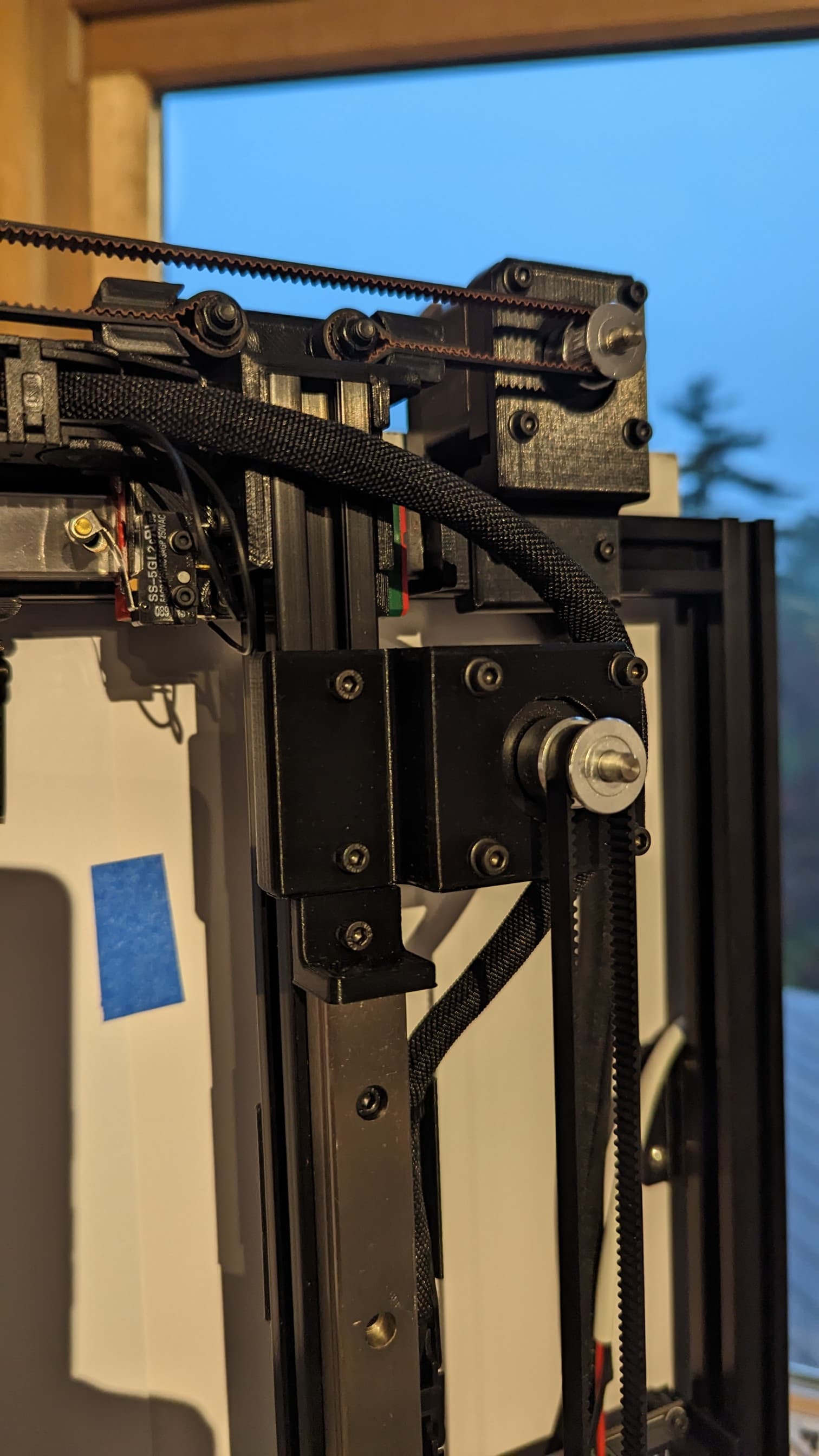
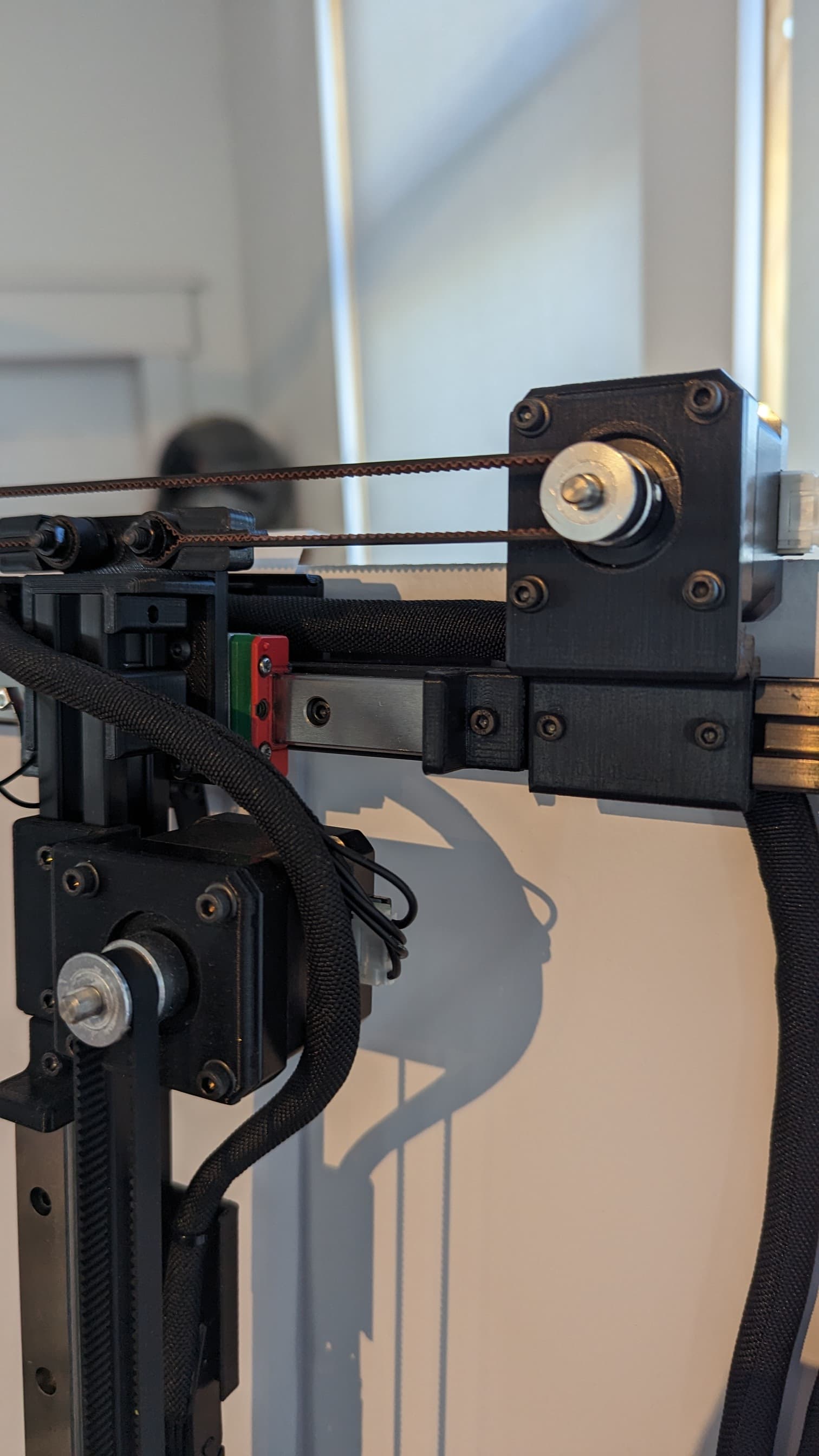
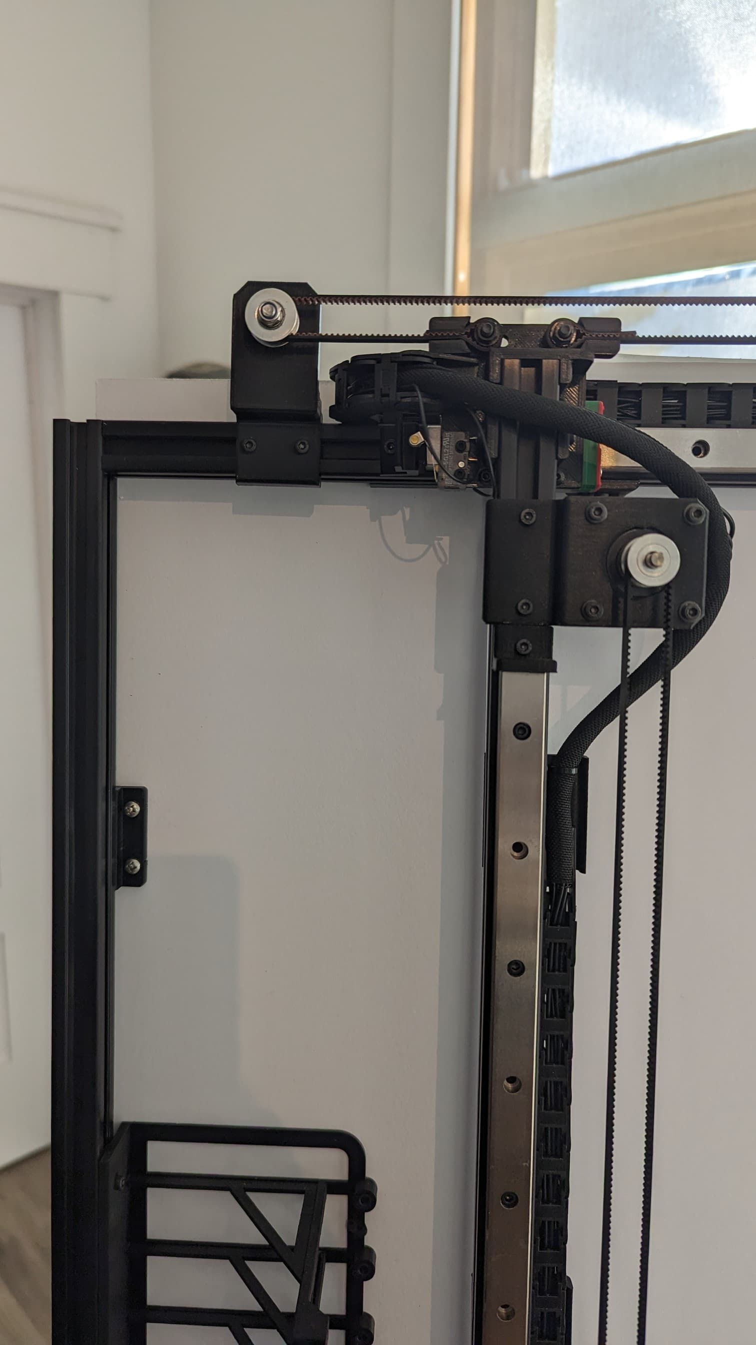
Upper X-Axis Motor Mount and Stop Bracket:
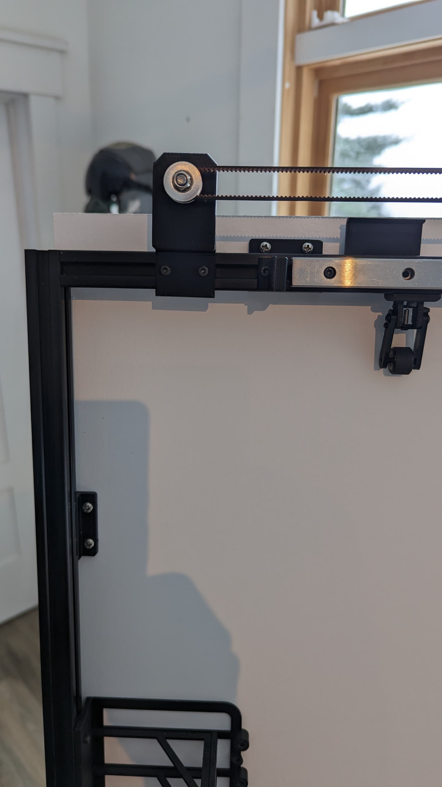
Upper X-Axis Idler Mount and Stop Bracket for Switch: !! Make sure there is at least an inch of extrusion showing between the idler bracket and the stop bracket or the drag chain won’t have room when the plotter is homing.
Lower X-Axis Motor Mount and Stop Bracket:
Lower X-Axis Idler Mount and Stop Bracket:
Idler Mounts:
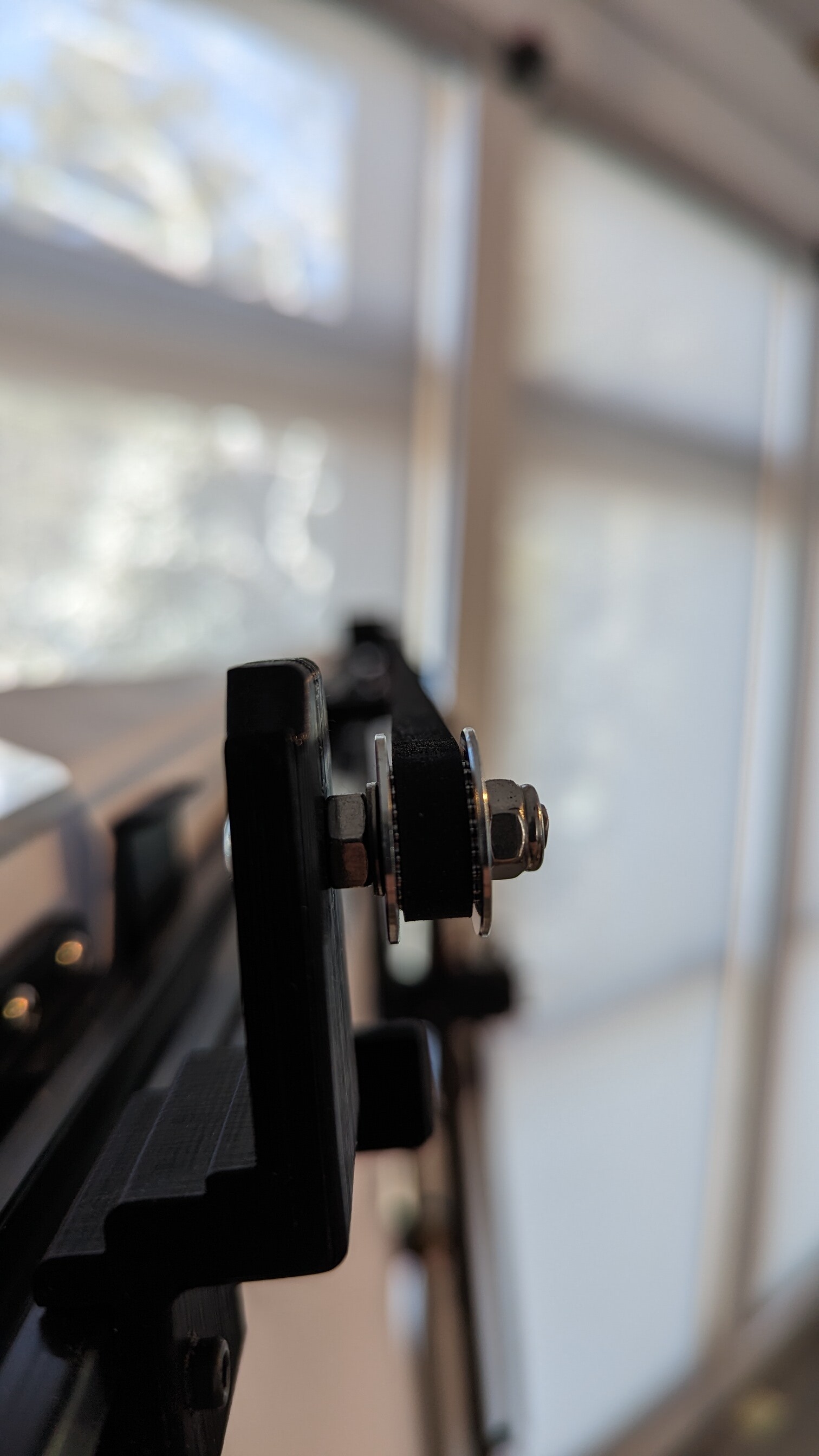
All three Idler Mounts use an M5x25 button head bolt secured to the mount with a regular nut. Then washer(s) are used as spacers in order to line up the idler wheel perfectly with the belt, then the idler wheel is held in place with a Lock Nut. I used one spacer washer on each of the X-Axis idlers and three washers on the Y-Axis idler. The lock nut is tightened enough so the idler wheel can’t move in/out along the bolt shaft, but not so tight that the wheel binds.
Note about the motor shafts and pulleys: Some of the motors I have used have had almost the entire shaft keyed (the flat area), while other motors don’t (just the outer portion). My design requires that the pulley wheel is positioned very tight to the base of the shaft (to reduce the moment arm). In order to ensure that the set screw contacts the flat part of the shaft, I had to take a file to some of the motor shafts in order to extend the flat area closer to the base. You can see what I am talking about by looking at the 1st of the 5 pics above. It shows the upper X-Axis motor and the Y-Axis motor. Notice how the end of the shaft is proud of the pulley wheel. This would not be as important if the mounts were made out of aluminum or steel, but the plastic mounts have a tiny bit of flex, so a shorter moment arm is important. This is where ABS is strongly recommended over PLA for the motor and idler mounts since ABS is much more rigid.
Edit: The accuracy of the above statement regarding the rigidity of ABS vs. PLA is debatable. So, I will rephrase and recommend that you print the mounts out of whatever material and print settings that will produce mounts with the least tendency to flex.
Note about the timing belts and mounts: The belt mounts were designed so the belt fit is very tight. It’s a bit challenging to get the belt positioned in the slot, but it will fit. Reference the 1st and 3rd of the 5 pics above for pictures of the belt mounts. The belt mounts are attached to the trucks using M4x20 socket head bolts with washers and a lock washer. One of the holes on each truck is slotted. Initially this was intended as a way to tension the belt, but don’t bother with that. To tension the belts, I loosen the bolts on the idler bracket mounts, tension the belt as desired, then tighten the bolts. It is worth mentioning again - Refer to the 2nd of the 5 pics above - Make sure there is at least an inch of extrusion showing between the upper X-Axis idler bracket and the stop bracket or the drag chain won’t have room when the plotter is homing.
3 Likes
Y-Axis Assemblies
3d Parts
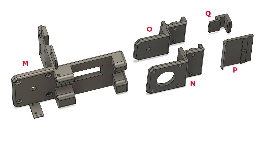
M. Y-Axis Truck (Pen Carriage) (1)
N. Y-Axis Motor Mount (1)
O. Y-Axis Idler Mount (1)
P. Small Drag Chain Cradle (5)
Q. Y-Axis Stop Bracket for Homing Switch (1)
y-axis_3dmodels.zip (110.2 KB)
Note: You’ll also need 1 Stop Bracket and 2 Timing Belt Mounts from the X-Axis parts.
!! First thing you want to do is attach the Chain Cradles to the underside of the extrusion. Much easier if you remove it first. I suggest socket heads for those. You can keep the bolts loose enough to slide the cradles so you can position and tighten them later. Unlike the large cradles on the upper X-Axis, these have enough clearance to access after the extrusion is installed.
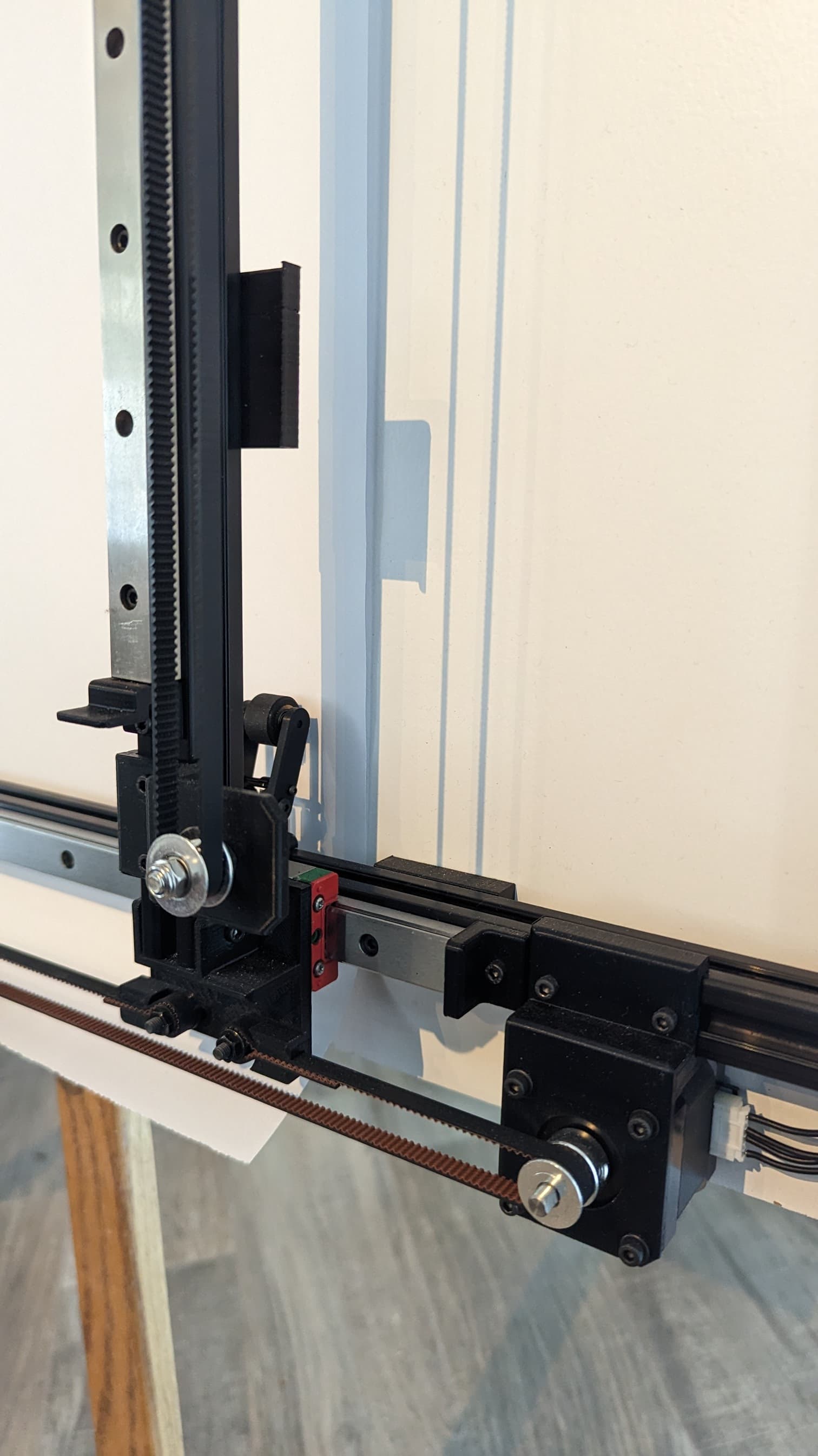
Y-Axis Truck mounting: First off, there are two holes (for the drag chain mounts) that are sized to accept the M3 brass nuts that get installed with a soldering iron. You can do that later, but it might be easier to install those on the bench now. The Z-Axis motor sits right on top of two of the bolts that attach the Y-Axis Truck to the MGN15C rail block. They go in the two holes that are recessed. Those 2 bolts need to be button heads. You can use socket heads for the other two. Note that the “other two” will need to be removed in order to mount the motor. So, if you have the motor available now, the order should be: Install the 2 button head bolts, Install the Z Motor, then install the last 2 bolts. You can see those last two bolts in the pic below, just to the right of the motor body.
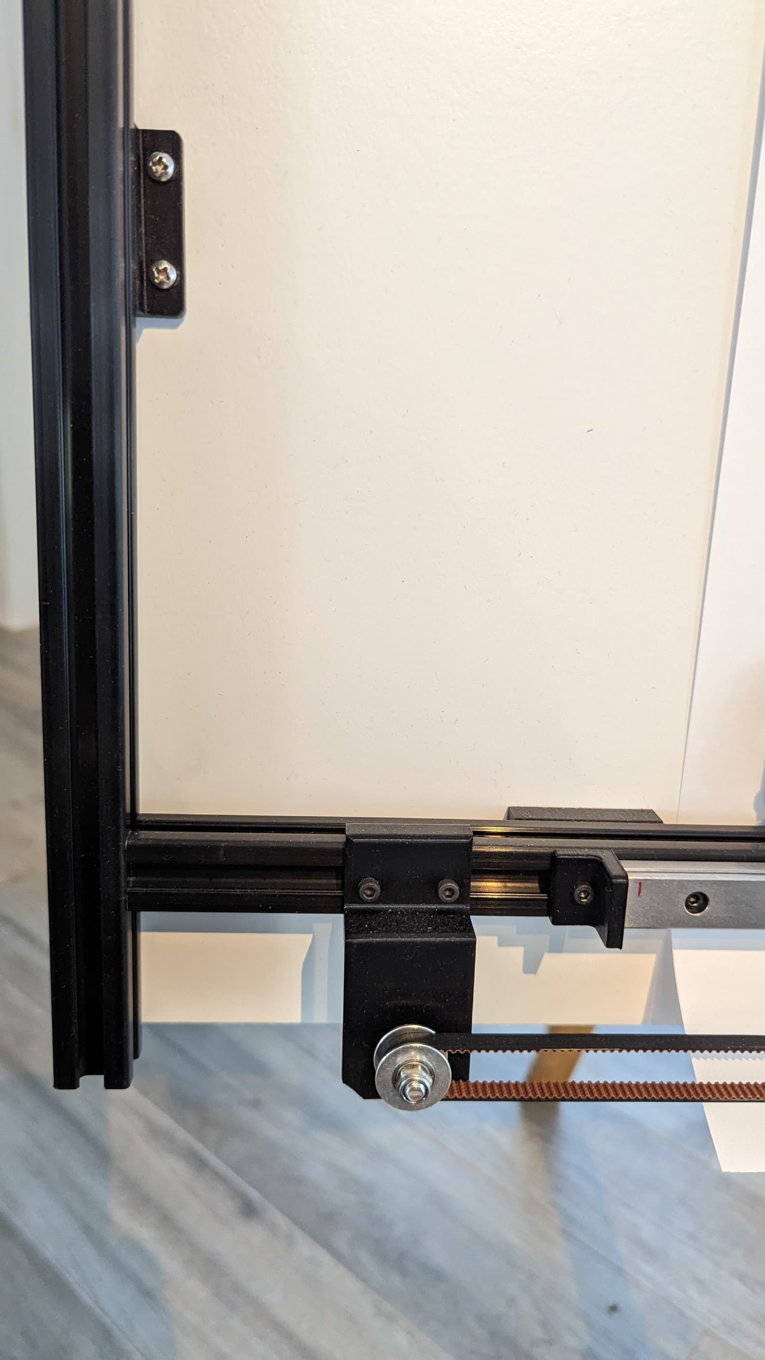
Y-Axis Rail and Idler Position:
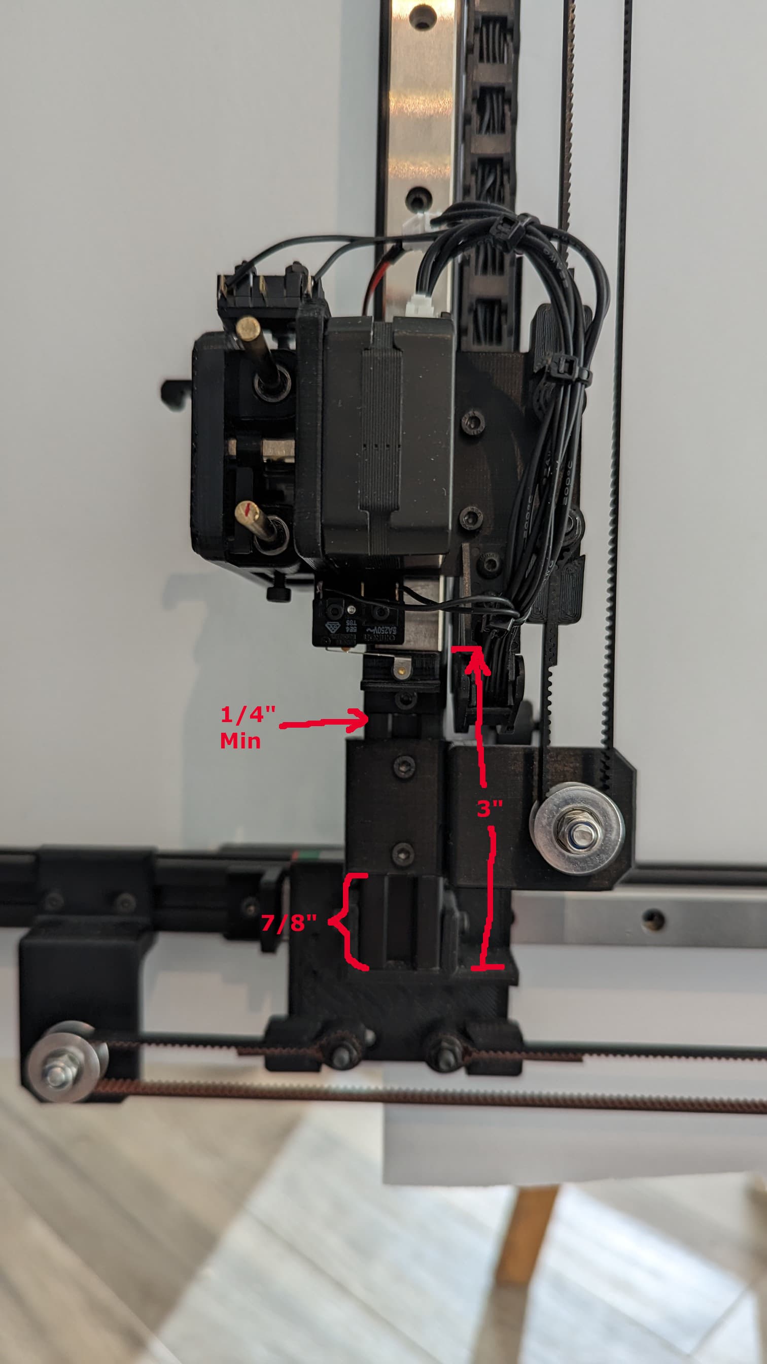
Things are a bit tighter on the Y-Axis. Start by positioning the rail 3" from the bottom end of the extrusion. Put the Stop Bracket (for Homing Switch) tight up against the rail. Leave at least 1/4" space between the stop bracket and the idler bracket to ensure room for the drag chain during homing. That should leave about 1/4" of movement for belt tensioning. There is also a little room to slide the motor bracket at the top if you need it.
Y-Axis Motor Mount:
Mount the stop bracket so it is touching the top of the rail and place the motor mount touching the stop. That will give you about 1/4" to move the motor for future belt tensioning if you need it.
Y-Axis Idler:
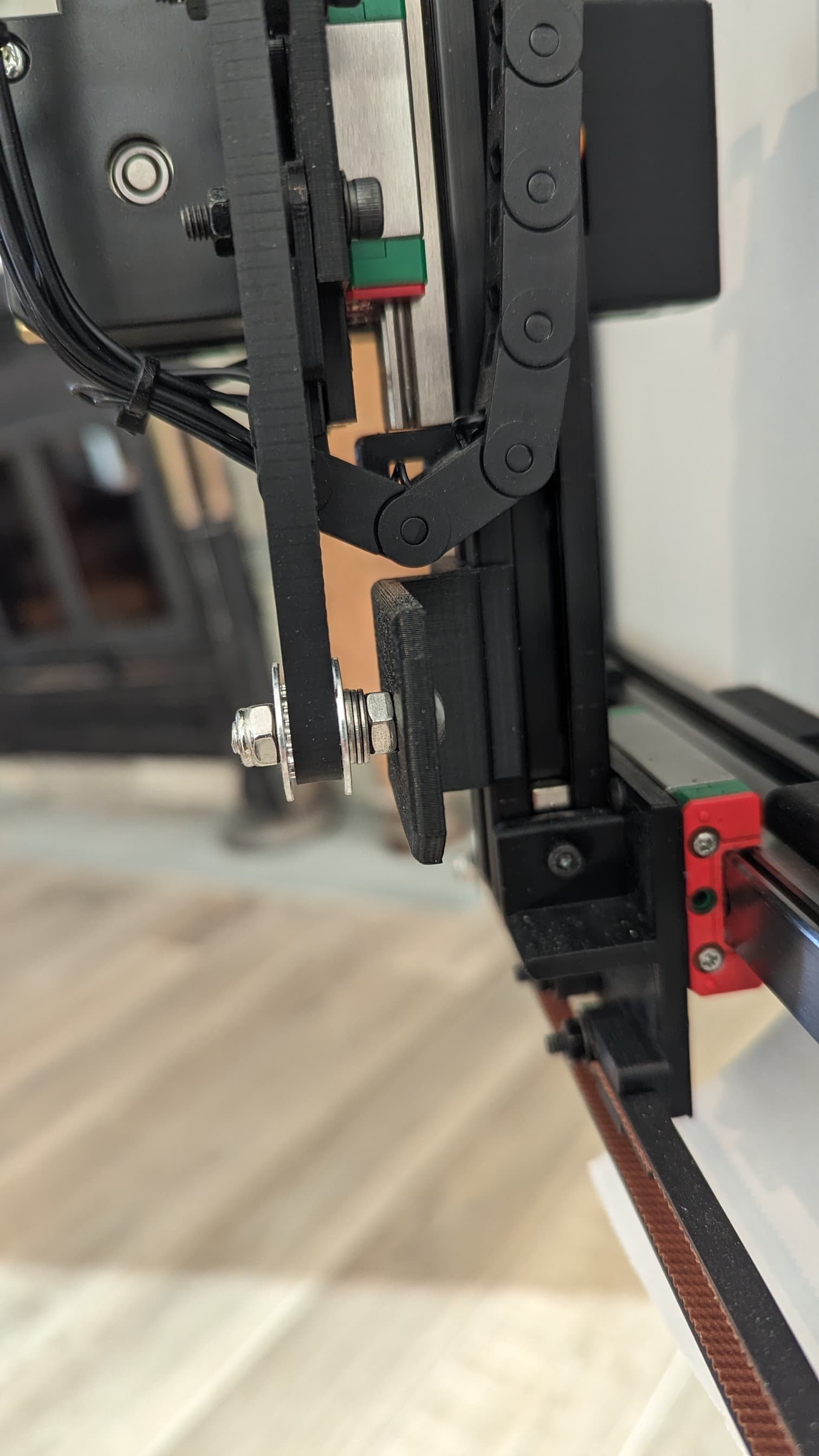
Notice I needed 3 washers for spacing. This is also a good view of one of the bolts and t-nuts that attach the extrusion to the truck.
3 Likes
Pen Holder Assembly
3d Parts

R: Pen Holder Bracket (1)
S: Lifter Arm (1)
T: Slider (1)
U: Bracket for Sakura Pigma Micron pens
V: Bracket for Staedtler Pigment Liner pens
W: Bracket for Uni-ball Power Tank Retractable Refill cartridges
X: Sleeve for Uni-ball Retractable Refill cartridges
pen_carriage_3dmodels.zip (117.7 KB)
Suggest you print all of these using PLA or a similar soft/flexible plastic. You’ll need support for the Lifter Arm (S) but don’t use any on the Slider (T). Your choice on the rest, but you shouldn’t need any.
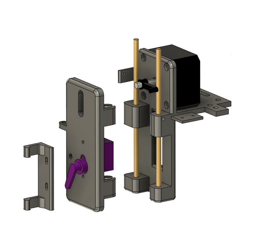
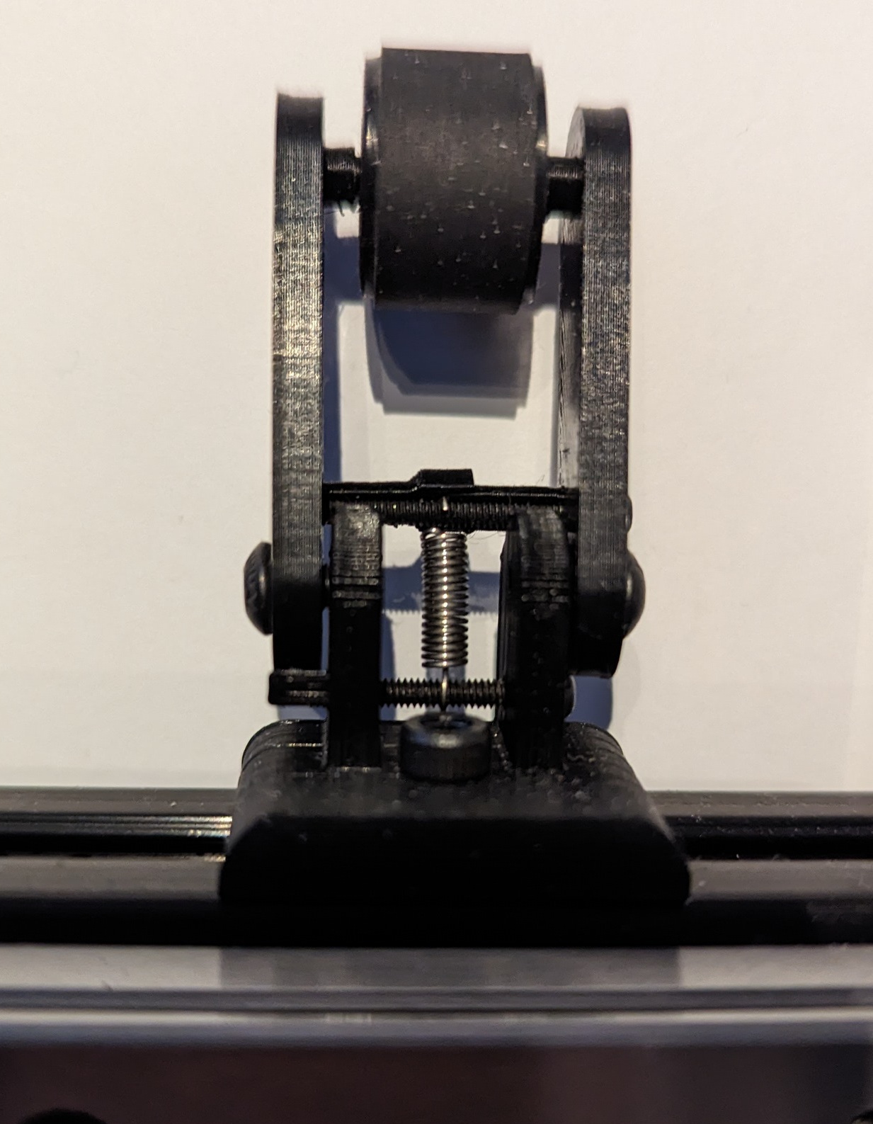
The spring ( 1 5/8" x 7/32" x .015 WG) is not shown in the exploded view above, but it is shown in the second picture below.
This pic is taken standing in front of the plotter looking down at the top of the assembly:
This pic is taken kneeling if front of the plotter, looking up at the underside of the assembly:
This is the most temperamental assembly on the machine. In order for things to work correctly, the Slider (T) must move smoothly up and down on the 4mm rods. The lifter mechanism is just that… a lifter. It does not force the pen down onto the paper, it allows the slider assembly to be moved down by the spring. The spring is relatively weak (intentionally), and if the bearings bind on the rods even slightly, the pen will not contact the paper correctly. If you use a stronger spring, the fine liner pens will contact the paper with too much force.
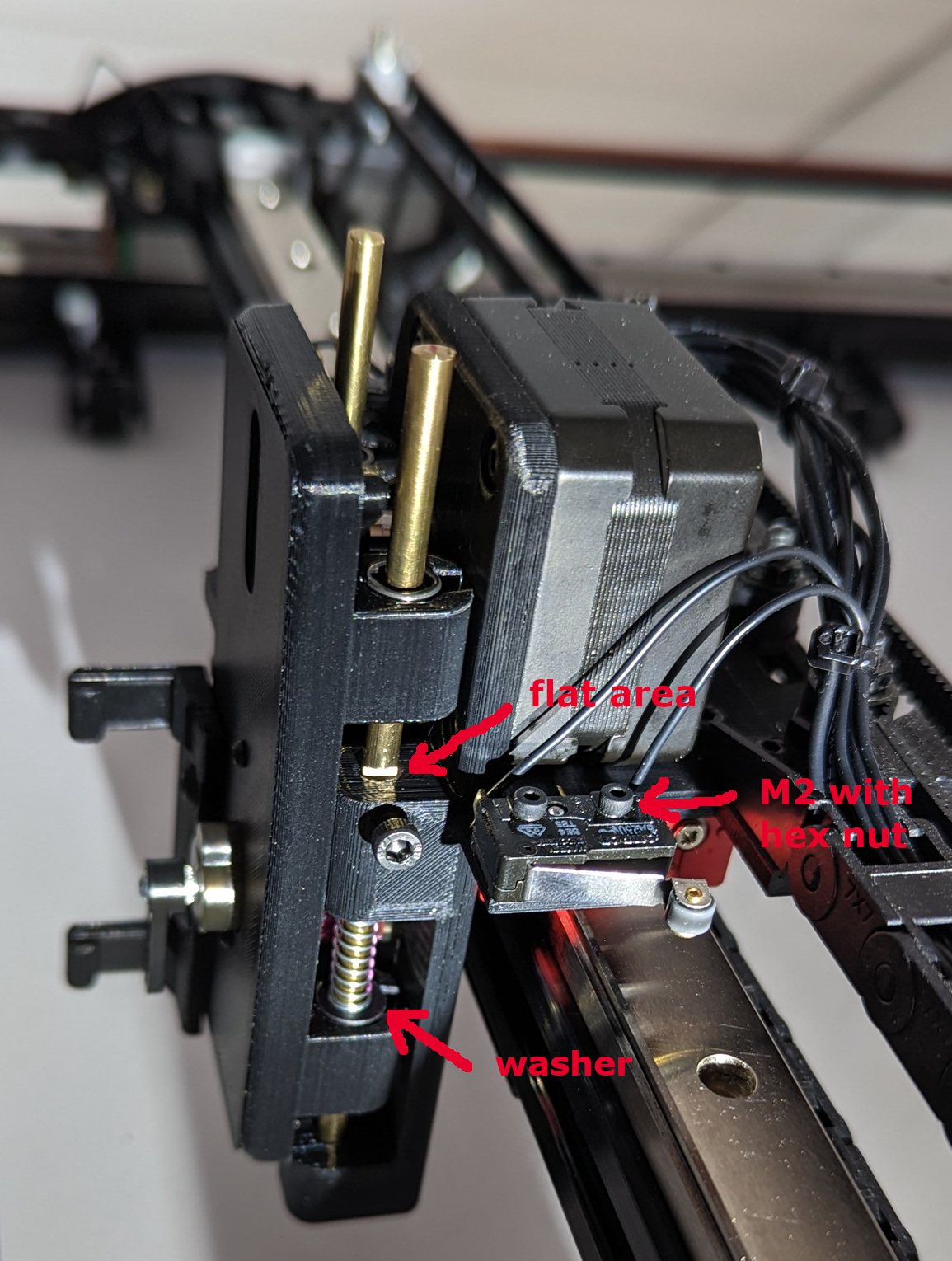
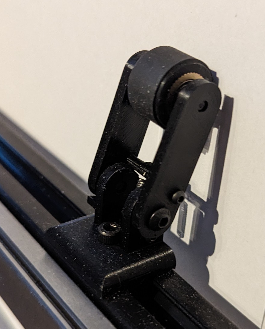
- Using quality LM4UU bearings and rods go a long way. If you have some decent 4mm stainless-steel rods hanging around, you can give them a shot. I found them to be a little larger in diameter than the brass and more likely to bind. SS rods will fit snug on their own, but the brass ones I used are a little loose, so I filed a flat area in the appropriate places and used set screws to keep the rods from sliding out (refer to pic above). DO NOT tighten the set screws!! Just enough so the rod can’t slide out, but the rod should be allowed to move around.
- If the assembly still binds, it is likely because some imperfections in the Pen Slider print (T) are causing one or more of the bearings to be slightly skewed. Trimming the edges of the bearing receptacles will fix this. My bearings fit pretty loose after I did this, but so far, they have resisted the urge to pop out.
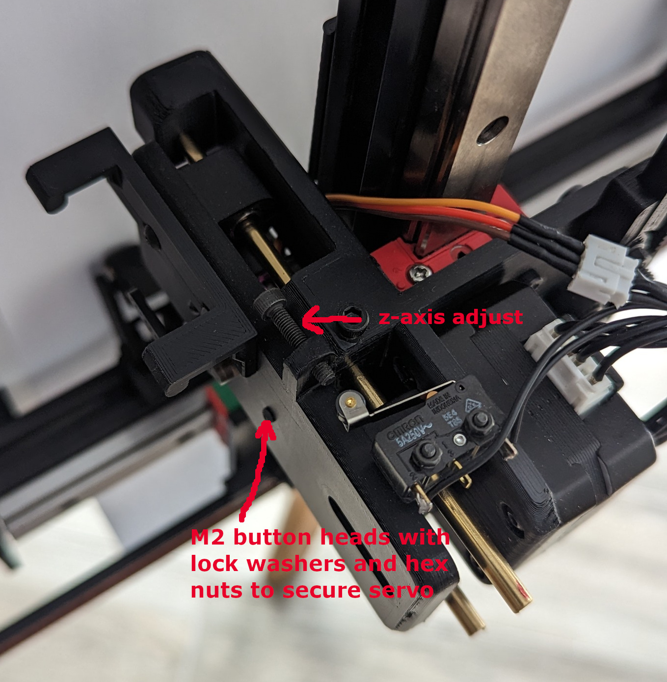
- The micro switches are attached using M2 bolts. The Z switch (1st pic above) uses button heads (there is very little clearance under the mount plate) and are oriented like in the pic (nuts on top). It must be installed before the Slider is installed. See the pic above for the Y switch attachment (the nuts below the mount plate are not visible).
- The Pen Holder Bracket (R) is attached to the Slider using 2 M3 button heads that thread into brass nut inserts (installed with a soldering iron). It is important that the bracket (R) sits perfectly flush onto the surface of the Slider. Suggest you set the nut inserts slightly lower (recessed) to the face and trim off any excess plastic that will spill out during the melting process. It is equally important that the button heads are tightened so they are flush with the surface of the holder bracket (R). Use the shortest bolts possible. Either of these can result in problems grabbing and holding pens. The holes in the bracket are oval. For now, install it so that the bracket is at the lowest possible position on the slider.
- Installing the M2 hex nuts that hold the servo on the Slider (T) is not easy. They are slightly larger than a grain of sand and there is not much room for fat fingers. Just sayin’. Hang in there. And the spring and washer can be a little tricky as well.
- The Lifter Arm (S) will need to be positioned on the motor shaft so it does not contact the 4mm rod and just enough of the arm gets inserted into the keyway on the Slider, but no other part of the arm contacts the slider body.
As always, if anyone has any better ideas for the pen holder assembly or any other parts of the build, I’m all ears. The pen holder assembly did wind up a bit overly complicated, but I wanted it to be able to accept several different kinds of pens. There are also the challenges introduced by gravity, which are not present on a tabletop plotter.
3 Likes
This all contradicts my understanding of filament rigidity based on conversations on this forum in regards to Lowrider/MPCNC printed parts. I believe that PLA is more rigid than ABS. If you wanted something with slight flex, I would likely use PETG. Where ABS or PETG has an advantage over PLA is with dealing with higher temperatures which I don’t believe would be an issue for this project. It sounds like you can’t really beat PLA for rigidity until you get to something like PET-CF/GF.
I’m following along closely with all these updates. I’ve been doing some measuring around my house on where I could put one and what size. I definitely have more wall space than floor space so this being wall mounted is awesome.
4 Likes
I don’t have much experience with PETG, but that may be a better option than PLA for the pen lifter parts. I have printed a lot of stuff in ABS and PLA, and I find that PLA will “give” a little bit more than ABS before it cracks, as ABS is a bit more brittle. But I find ABS to be more rigid (harder) and certainly more heat resistant. I won’t claim to be an expert though. Maybe it’s just my printer settings. I use an Ender 3 for PLA and a Voron 2.4 for ABS.
1 Like
Yea, me neither. I at least understand your intent.
Miscellaneous Parts
Drag Chain End:
The larger drag chain that I purchased (the one that runs along the top of the plotter) wouldn’t lay flat with any of the included ends, so I made this one. It attaches to the upper x-axis truck with a couple short M3 button heads that thread into brass nut inserts installed in the truck. I attached the other end of the chain to the right-most chain cradle with a short button head bolt (no nut), just drilled a small hole in the plastic slightly smaller than the bolt’s shaft diameter and threaded it in.
Jackpot Mount:
5 Position Pen Holder:
Small magnets are inserted into the hole on the top of each post. Be consistent with the polarity! Small o-rings (4x1mm or 5/32" x 3/64") fit into the top of each pen tip “well” on the base. The idea was to seal the tips to keep the ink from drying up when the pens where in the holder (with their caps off).
Friction Rollers:
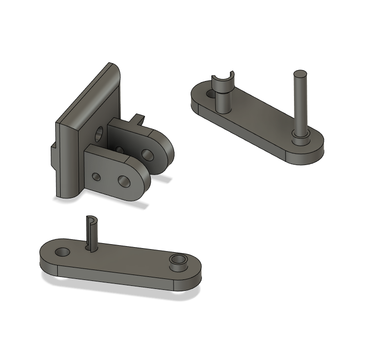
Each roller needs 1 M2x20, 1 M2x16, 2 M3x6s and a spring as specified in the BOM. I used button heads for all the bolts. Assembly is delicate and awkward (I broke a few), but they work great once assembled and installed. The M3 bolts work like hinge pins and thread into the holes on the sides of the base. I widened the holes in the two side pieces with a 3.2mm drill, so they rotated freely around the M3 bolts. Otherwise, the threads will grab and cause binding. When I get a chance, I’ll modify the 3d model files so that won’t be necessary.
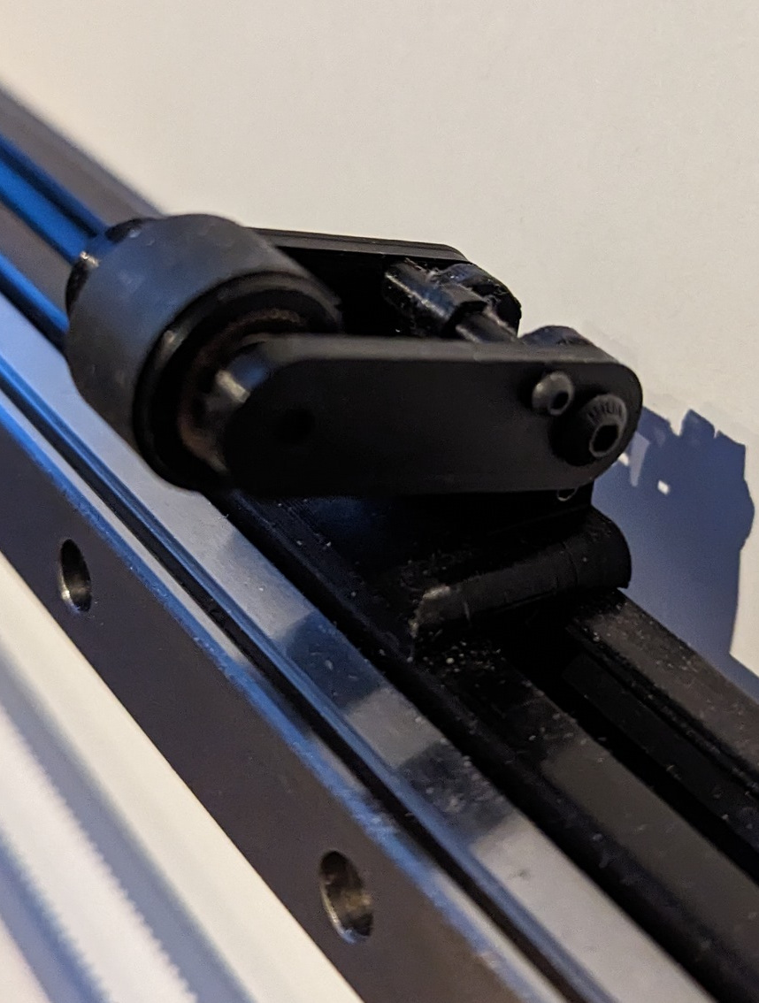
The rollers are designed to fold back out of the way while loading paper.
3d Model Files:
misc_parts.zip (208.4 KB)
PLA works well for all of these parts.
6 Likes
Wiring and Config
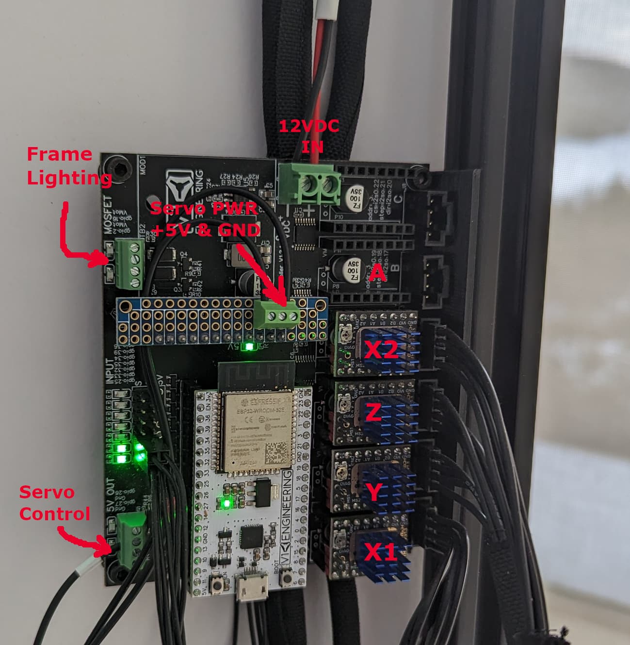
- Motor and switch wiring is self-explanatory (I must have taken this shot during the z-axis home cycle). I always test the X1 and X2 motors separately to make sure I got the direction right. If they go in opposite directions at the same time, things get ugly fast.
- The paper roll advance motor is not hooked up in this picture. That’s a work in progress as I write this. However, if you use slot A for the paper advance motor, the corresponding code is in the config.yaml (link below). That section is commented out with #s.
- Servo control wire is in the second spot from the bottom (gpio.27).
- Frame lighting (12v led strip lights) use the MOSFET outputs. I use both. One for the top and bottom (gpio.16), and one for the left and right (gpio.2). Reason - gantry shadow. I found the shadow cast by the left and right side lighting to be annoying, especially when the Y-axis moves back and forth during plotting. The lighting is controlled using the M67 command.
M67E0Q100 turns the lights that are hooked to gpio.16 to bright.
M67E0Q0 turns them off.
M67E0Q50 turns them to 50% intensity, and so on.
If you use gpio.2 as I did, then the commands are similar to above except replace E0 with E1.
M67E1Q25 turns the lights hooked up to gpio.2 to 25% intensity.
…
config.yaml.nc (7.8 KB)
Notes on the config.yaml
- I added the .nc extension so the forum let me upload it without sticking it in a .zip file.
- In addition to the “a:” section as mentioned above, there are some other lines that are commented out (with #). These are settings used by the newer version of FluidNC. Most have something to do with homing. I believe they are added automatically, but I included them as a reference.
- I removed a setting from the macros section of this config that causes automatic homing after power-on and resets. After everything is calibrated and working, you might consider including the following:
macros:
  startup_line0: $H
Helps prevent alarms and/or crashing.
- There is also a max_travel set for the X and Y axes with soft_limits set to true. This will prevent crashing (assuming the machine has been homed) and will throw an alarm if your g-code goes out of bounds. Note that the numbers in this config.yaml are for 1000mm rails. If you made a smaller machine, those numbers would be smaller. For example, if you cut 6" off the X axis rails, you would change “max_travel_mm: 932.000000” to “max_travel_mm: 782.000000”
- The z-axis max travel value is set pretty tight, so if you get an alarm during z-axis homing, you might need to increase the max travel by 1 or 2 mms.
- The Servo travel is set in the BESC section. You will undoubtly need to adjust the values for “min_pulse_us” and “max_pulse_us”. More on that in a future post.
6 Likes
Hey @vicious1 , appreciate it if you keep me in the fairway regarding the config settings, etc. I was humbled when @jeyeager called me out on the PLA vs ABS stuff. Last thing I want is to spread bad info. Still trying to figure that one out. Sometimes I don’t read the manual and pull from personal experience. Can’t argue with accepted science though. I’m blaming it on the hundreds of slicer settings. ![]()
2 Likes
If your config works you are doing just fine!
3 Likes
This is such a fun project and such an entertaining idea.
I love generative art. The idea that you can create a brand new random piece of art automatically, from a robot is awesome to me.
But you realistic drawings are incredible too. If they were any more realistic, you might as well be using an inkjet. Doing them this way is incredibly fun.
6 Likes
All of this.
I’m lurking on this thread, and loving it. Such a fun project, and appreciate @Stoli sharing all the details.
5 Likes
Mod 1
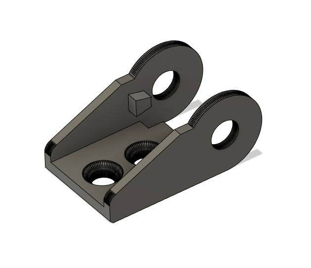
As I was writing up some calibration instructions, it occurred to me that a small modification in the X-Axis Stop Bracket for the Homing Switch (Part H) would make it much easier to adjust the Machine X=0 position.
Here is the new part with a few pics. I installed an M3 brass nut (heated insert) and used an M3x16 socket head bolt with a nut on one side to lock it in place after calibration. It will be much easier if you attach the part to the extrusion before you thread in the adjustment bolt.
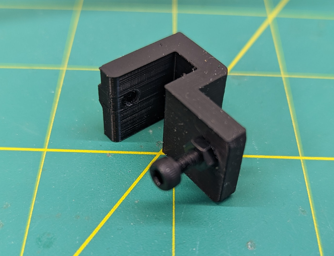
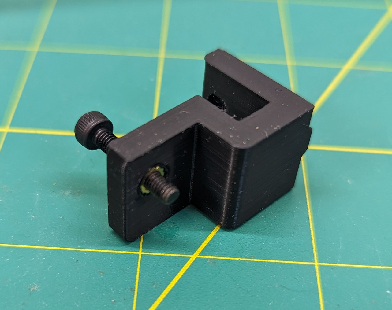

Since it is possible to mount the bracket in such a way that the X-Axis crashes into the stop before the switch is triggered, I recommend manually checking it (with the power off) before trying to home. That’s about a 3mm gap between the stop bracket and the end of the rail and the adjustment bolt is sticking out about 4mm.
mod1_3dmodel.zip (11.9 KB)
1 Like