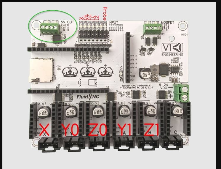
I am almost done with the LR4 mechanical build and have started working on the V1 Shop loaded Jackpot with FluidNC preloaded and am trying to get the dial to connect. I have purchased the circuit board for both ends from Elecrow. I do have power on the M5 Dial, and a working FluidNC display but no connectivity to the Jackpot board. Without seeing the code on the Jackpot, it would seem it does not have UART2 enabled going out gpio14 and 15 for comms. I think this means I need to reflash it with add of the UART statement for UART 2 indicating those gpios?
Another question for the Jackpot. Can an output be set to turn the spindle router on and off when the cycle starts? I see lots of YouTube video and folks are turning the router on and off manually. Can the flood pin be used into a solid-state or mechanical relay?
Thank you. I have read thru it again now that I am in the thick of it. I have downloaded FluidNC from Github and can find a uart.yaml. Although it doesn’t match Doug’s exactly, might that be the file to modify and push only that file to the Jackpot via web installer?
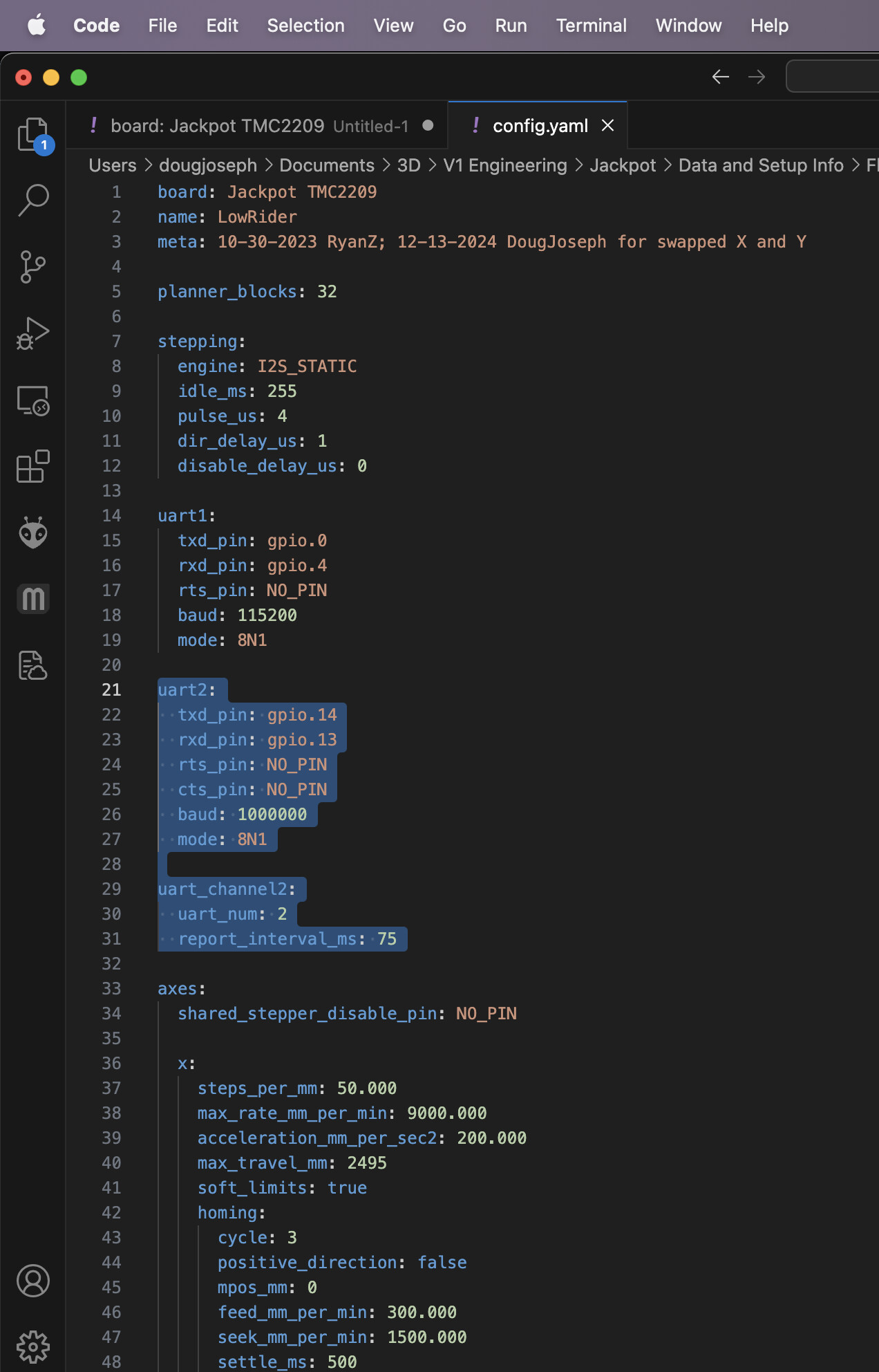
Actually you just need to edit your existing config.yaml and add the code for the additional UART right into the file. You can download your existing file from your Jackpot to a computer or tablet, using the WebUI, then save a new copy, edit it as needed, and upload the edited copy back to the Jackpot!
The GPIO numbers on the Wiki are based on a Bart Dring 6-pack board, while the GPIO numbers in my thread are based on a Jackpot board from V1E. The GPIO’s shown in my post, are what you need if you have a Jackpot!
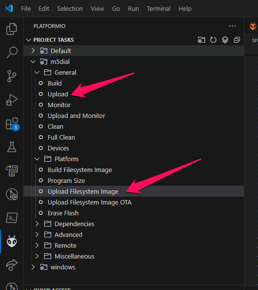
Exactly what @jeyeager said. For convenience, I copied the pertinent part from the wiki he linked to, and will paste it here. This is a screen shot from using VSCode to install the firmware and upload the file system, which gets you your image files for the buttons:
Upload the image files
Open the Platform folder and click on Upload Filesytem image
Doug, I’m trying to get my M5Dial running but when I go to the Github link “https://github.com/bdring/PendantsForFluidNC/tree/main/M5Dial_Pendant” you referenced earlier I get "404 - page not found The main branch of
PendantsForFluidNC does not contain the path M5Dial_Pendant.
@DougJoseph Hello Doug , I have assembled my M5 pendant and somehow successfully uploaded firmware to it. Software issues always have me chasing my tail! The dial powers up and says not connected which is right because I am unsure of how to reconfigure the gpio pins on the uart on Jackpot board. Would it be to much trouble to post a step by step? I don’t know how to access the config.yaml to add the script. Do I need to plug in a PC to the USB on the Jackpot to accomplish this? I have read all the posts that I could find on this forum in regards to the M5 pendant. Thanx hope are well
You can use the Wifi connection to access the files on the Jackpot remotely from your computer, download a copy of any of the files, edit as needed (save a backup first) and then re-upload to the Jackpot. You will need to reboot the Jackpot for the changes to take effect.
This link leads to a post with key info:
although in the screen shots of editing my config.yaml I highlighted part of the new code, but forgot to highlight the new UART section just below it. That was caught and a clearer example of the needed code was shown here: