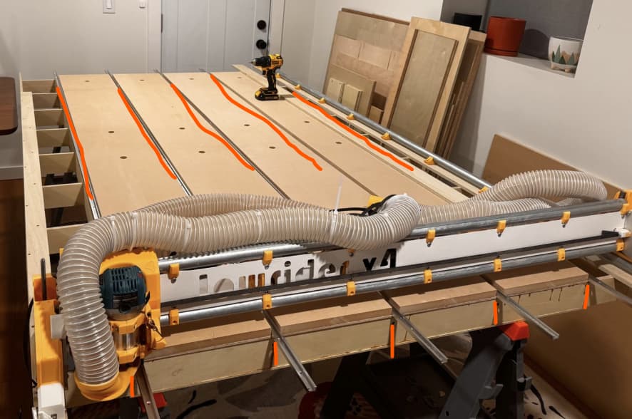
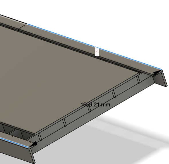
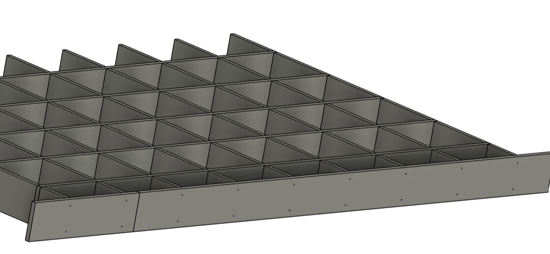
Did you line up the Y axis supports with the T track?
And did you add extra X,Y axis dimensions so you have the ability to clamp a 4x8’ plywood on the edges? I would think it needs an extra 6” to 8” on each side right?
Sorry for all the questions but my head is buzzing. I really need a table but I only want to make one lol.
I am planning to 3D print some kind of arm that can go underneath and prevent movement along the X axis. Normally when I have a big sheet clamped down at front/back it doesn’t move enough anyway for me to be too worried about it.
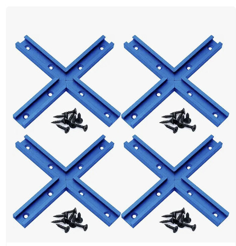
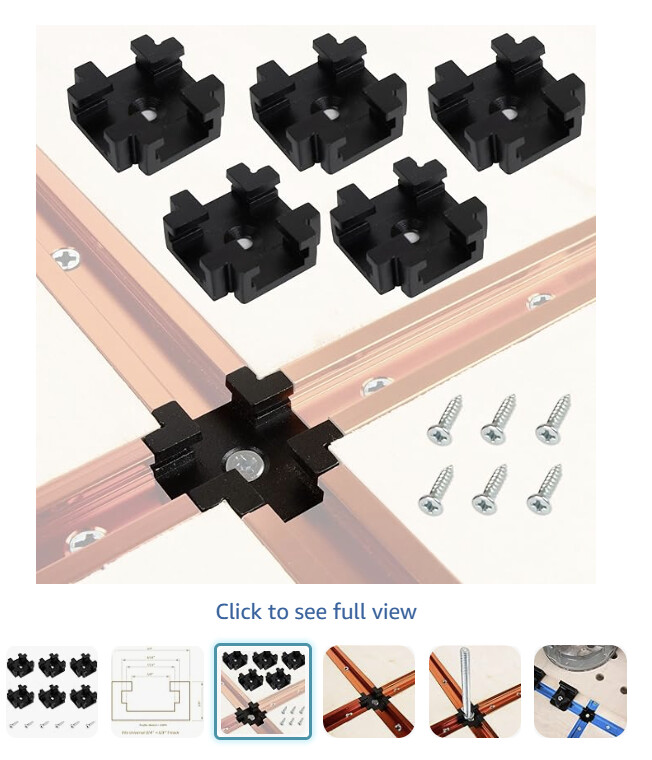
My 1/4 mdf I was cutting for the strut plates was bowing up in the middle and needed screwed down along the long edge which is why I am asking about it. I was thinking maybe adding these to the table to give clamping along that edge?
I just used wood screws for this. I set the cutting order in EstlCAM to cut the holes first, then pause, and then cut the parts after the pause. During the pause I inserted screws in every second hole.
If necessary, you can simply press down on the MDF with your hand during the hole cutting, until you have a chance to install the screws during he pause.
It worked very well, but you need to ensure that your Clearance Plane is high enough not to hit the screw heads during travel moves.
@Colin_S I’ve updated the site to add 5% of the total table thickness as a buffer. So you should have plenty of room to tap the spars flat (in fact they will go a bit past each other, but that shouldn’t be an issue with the skins attached.)
Thanks Zach! I am currently trying to understand what all the parameters do and trying to 3d CAD it in fusion using the SVG file. I am OCD about things. I had some questions about it:
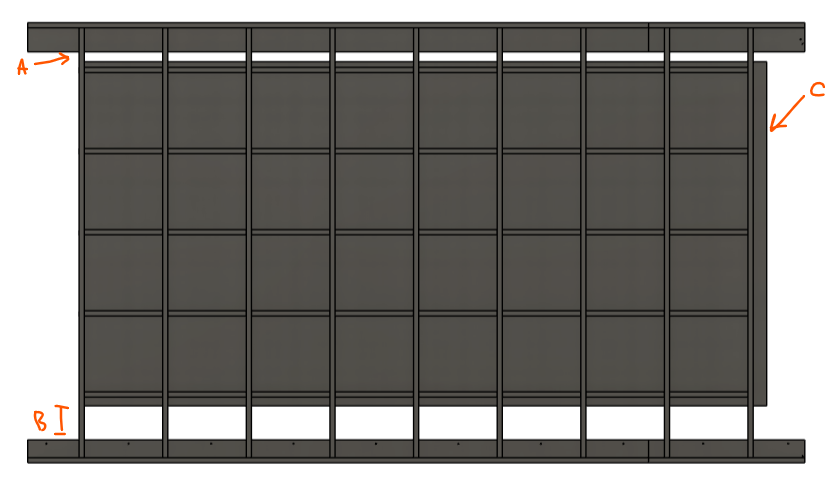
Are there any drawings from Ryan that show critical distances when designing a table? I am trying to determine distances A and B in the picture.
Should there be an overhand on the Y direction for the top plywood board? See “C” in picture below.
No, there aren’t. The best I can do is measure the drawing from Ryan’s table design which I found here . You can see me going through the process in this very topic.
The overhang should be equal on all sides. It’s configurable in the UI.
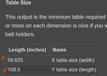
Your drawing looks right (I see the same error). However, I have built two tables from this and neither were too small (if anything, they were a bit too big?). I will go over my new table tonight and try to confirm all the measurements to see what’s up.
Having the table be slightly too narrow is actually the better case if they are off in either direction, because attaching the rails slightly wide will still give them the full support of the side rails + most of spars.
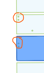
Yes, that’s expected (they are actually two half circles.) It’s a bit of a hack to make the generator easier for me to implement. All the software I’ve played with (admittedly, just vectric + estlcam) handles this fine.
I tried to split the difference here with the placement hint lines. I figured each person would shift their rails around a bit trying to get the machine placed exactly right wrt the spoilboard. Pre-drilling holes commits you to a specific layout.