The 'Black and Blue' LR3 build

Hi Everyone

Been lurking and occasionally posting for a couple years now, with the intent of building a LR2 for my woodworking shop. However, pandemic lockdown played a trick on us and blessed us with a baby boy, so everything got put on the backburner while we found a new place to live, and got things squared away. Been homeschooling two girls since March 2020, so not a whole lot of time for hobbies, but seeing how im being slowly driven insane, I need an outlet. So I came back to the site intending to buy an LR2 kit, and was very excitedly surprised to see the LR3 development.

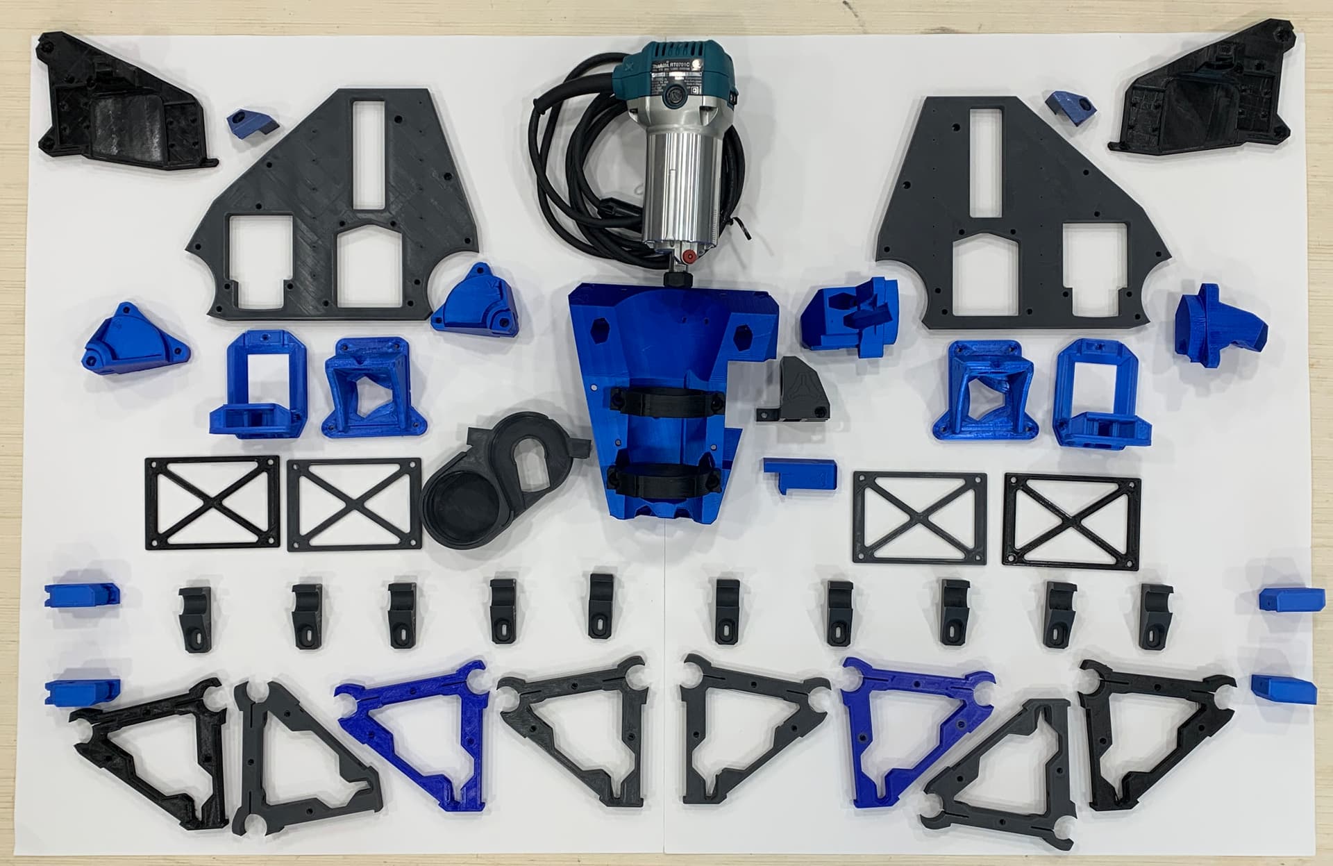
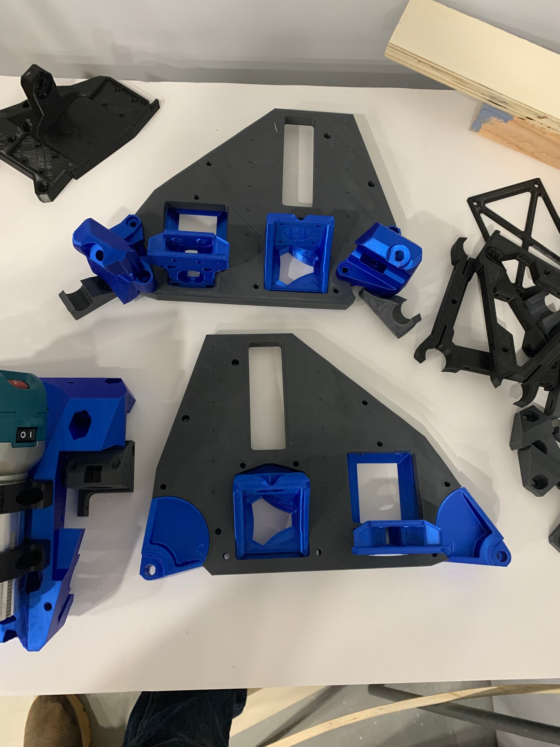
So, im jumping in with both feet, and have printed up all the parts over the past week- my 6 year old CR10 clone has been churning away practically constantly.

Plan is for a 36"x60" work area, with a knock-down table to avoid cramping my small 17x17 woodworking shop. I posted previously about plans for a fold up table, but I recently saw a table design by Michael Cunningham (@Mcunn) that is perfect for my needs, so im looking to adapt it to work for the LR3 Portable Lowrider in Annapolis

Plan to order the LR3 kit plus endstops and the SKR Pro1.2 package later this evening, and get to work building.

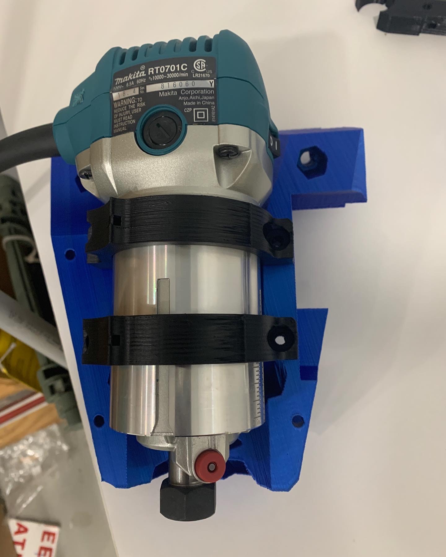
Was able to pick up a refurbished Makita for $35, and @DougJoseph shared STLs on printables for a 2.5" dust collection boot- which means i can hook it up to the shop DC instead of a noisier shopvac.

Thanks for checking out the build!


13 Likes

Great work! Will be keeping up with it.

Speaking of the remixed dust shoe, I’m about to publish a YouTube video that shows some tidbits about it. The video is not yet fully uploaded, but when it becomes available it will be on this URL:

2 Likes

I’ll be sure to check it out!

Am I correct in thinking that if I get the SKR board and LCD, it should just work when I connect it and power it all up, since it’s pre-flashed?

Or do I still load up bins and flash them depending on my use case (dual end stops)?

Yup, should just work. If there are any issues or updates flashing it is simple.

1 Like

Could you help me on what screw sizes go to what? I want to start putting some screws in place but dont want to start putting all the screws in then find out i needed ut somewhere else. Thank you in advance

1 Like

Here are the V3 docs.

https://docs.v1engineering.com/lowrider/

1 Like

The hardware list shown here is helpful: LowRider CNC V3 - V1 Engineering Documentation

You’ll notice that there are only a few sizes. In true “engineering wisdom” fashion, Ryan deliberately and carefully designed it so there are lots of uses of the same size. Thus, for the most part, you need a lot of one thing, instead of a few of many things.

The quantity 14 of M8 x 40mm (imperial alternate 5/16” x 1.5”) go for the roller bearings.

The quantity 100 of M5 x 30mm go for almost everything as far as fastening parts together.

Note: I had a bunch of M5 x 25mm, and no 30mm, and so I started using them, and found that for the most part I could get away with using 25mm. One place I could not get away with 25mm, was attaching the sides (XZ plates) to the beam. Also, on things that attach to the YZ plate, which mine was thicker than spec, at 3/4" instead of 1/2", I was only able to use 25mm screws by use of a Forstner bit to counter bore the areas where nuts go on the outside of the YZ plate. This was light work since MDF is so easy to cut into.

The quantity 40 of M3 x 10mm are for attaching motors to motor mounts, and slide bearings to linear rods, and a tiny few other things I cannot think of at the moment. There are 5 motors x 4 screws each, for 20 of the 40, and 4 of the slide bearings at 4 screws each, for 16 more of the 40. So those two uses alone = 36 out of 40. There are only 4 left and I cannot remember now what they are for.

The quantity 10 of M2.5 x 12mm are for mounting end stop switches to their mounts.

The quantity 24 of 3mm x 12mm “Wood/metal” (imperial alternate #4 x ½” Wood or Sheet metal screws) are for attaching linear rods to the MDF YZ plate.

The quantity *22 of M4 x 12mm+ Wood/metal (imperial alternate #8 x ½“+) are to mount things to your table, including both your Y belt tensioner bases and your Y rail mounts (assuming you are mounting all that to a wooden table, and not to metal and/or plastic like I did).

*Not included in the hardware kit.

M8, M5, and M3 are so different from each other that there should be no chance that you would get confused on which goes where.

Hope this helps!

4 Likes

Awesome post, thanks for the input.

1 Like

One more tidbit on using my remixed dust shoe for 2.5" hose: whenever your LowRider 3 is fully assembled and in place, the Y rail itself encroaches the closest to the edge of the new, larger dust shoe (when the LR core is moved toward X-minimum as far as it can go), and so in order to make sure the X end-stop switch gets triggered before the dust shoe makes contact with the Y rail, I used a longer than normal M3 screw in the X end-stop screw hole in the X tensioner. Whereas a “standard” install would probably make use of M3 x 10mm in that spot, I think I used either M3 x 25mm or M3 x 30mm.

The loss of 15mm-20mm of travel in the X-min direction actually helped me, because I have some OSB wood “sides” at the edge of my table, to elevate the rails/tracks, and if it were homing all the way against a 10mm screw, at Z-min a bit could come down onto those sides. In other words, I have no need of those additional mm’s of travel, because it’s not over my spoil board — it’s over nothing I ever need to cut. As it is, at X-min (and Z-min) the bit can go down into a gap between those OSB “sides” and my MDF spoil board. For an image of my table to understand this, visit my LR2/table build thread here.

In my case, I would still use that longer screw for the X end-stop even if I were not using this 2.5" hose dust shoe remix. However, if for someone’s use, that loss of 15mm-20mm of travel is problematic, it would require revising the remix to rotate everything more toward the middle. That is doable, provided care is taken to make sure it does not create issues for access to change the bit when the bottom shoe part is removed.

1 Like

Thanks for the reminder- I saw this detail in your video where you described the new shoe and a couple other details.

Appreciate the help

2 Likes

Just tried this and an m3 screw is a little loose in there. I have some m5 laying around I think.

Hmm. Are you talking about the hole in the X tensioner for the end stop hinge to hit against? M3 definitely fits right and tight for me there.

Yep-

M3x20 in the tensioner hole… little loose


Hard to show the wiggle in pictures, lol

It’s fine- I can easily find an alternative

1 Like

Why are you using that screw?

The best option if you actually need to offset that is M666, or bend the microswitch tab.

1 Like

Because I’m using the 2.5” dust collection shoe which will hit the end plate before the end stop engages properly.

3 Likes

Ok, so I just burned todays ‘tinkering time’ while
Kids napped trying to flash the board and screen.

I hooked everything up as detailed in the docs, and was welcomed with a 3d printer interface, when I (erroneously) assumed that the board was already flashed and configured for CNC.

No worries- I downloaded the necessary files, and followed the instructions.

And am now faced with a worse looking version and still a hanky looking 3d print interface/

Since I’m not a coder, and I’ve essentially followed the instructions perfectly as written- I’m stumped. Anyone offer any insight into how to get this looking like a CNC interface?

Fwiw- I hooked up one stepper to the driver, and I can move it in both directions when using the movement tab.


After downloading the files and Re flashing- board first, with exp1 and 2 disconnected, then the TFT, I get this

Using the TFT files here


Next attempt using the tft files from here


You bought it from me and it wasn’t flashed?

Feel free to change it, all the files are available. In our download. Info on the SKR page.

What exactly are you looking for. We use the interface as is, any 3D printer specific stuff just ignore. It is far above my coding abilities to try and edit out buttons and try to keep a relatively current build. On that note I highly suggest you do not even use the touch interface. The Marlin side is far more stable and I only switch to run terminal commands if I don’t have my laptop with me.