Taking a closer look at the Jackpot and the EE involved with the Connectors

Check this out. While messing around in the other thread I had all the tools sitting here.

The Jv2 uses 0.52A at no motion with 5 steppers (Jv1 uses 0.55A margin of error), and 0.75A while all 5 steppers are in motion (Jv1 uses 0.76A).

Heat…
While holding.


In Motion, all 5 at once for a few minutes so I am sure it would get a bit hotter. Thermal shutdown on these is 120C…


There is an obvious difference in esp32 temp between this and the dev kit. This is barely even warm, vs hot as heck. I know heat sinks are the right move, but a fan moving air over the top and bottom of this board should easily be enough to run it, right?

1 Like

I can spread the drivers out a little bit more to get even better heat dissipation but that is a lot of work for what I assume would be not much gain. But you can clearly see the heat is in the middle. So maybe I suck it up and spend a couple hours moving everything.

Maybe I just add as many via’s as I can to transfer the heat instead of moving everything…

1 Like

The FLIR pics are neat, how do temps compare to Jackpot v1

Using 1oz, or 2oz copper for the PCB? If 1oz, would using thicker 2oz copper work good enough, and work out cheaper overall than including heatsinks for Customers attach? I like heatsinks, but appreciate it’s neat to strive for removing/simplifying components if/when possible.

1 Like

What if, given that it’s still not near the cutout temp and most people will only use 5 drivers, you label and configure the board to normally use the outside 2 and 3 drivers and leave one in the middle as the “6th” driver?

Perhaps X1, Y1, Y2, spare, Z1, Z2…

…or if you you expect that the Z drivers can be run cooler… something less organized (but possibly confusing and mistake prone) like X1, Z1, spare Y1, Z2, Y2…

…so a bit of a compromise, but more organized…

X1, Y1, Z1, spare (X2), Y2, Z2.

The only one I had handy already had heatsinks on it.

Good idea…I am not sure. More copper area but same surface area. Wild guess would be the same, maybe the heat would spread further faster??

I love this idea!!! Why not?

It would make a little more work on teh instructions but This is good.

I spent the last hour making sure there was as much copper around the drivers and adding 16 via’s per driver. So hopefully we get as much heat transfer as possible as fast as possible.

3 drivers active to the left, two to the right, the right side has the 5v and 3v regulators so they add a tiny bit of heat. That is about as balanced as it can get.

This is interesting.

Yep.

Guessing you have 1oz, which layer(s) are you dissipating heat? For 4 layer board, the inner layers are only 0.5oz by default? JLCPCB Copper Weight

Yeah.

Top and bottom are ground layers. One of the middle layers also has a ground patch tying them together but no heat gets dissipated from the middle, that would just help move heat if there was an imbalance.

Dam, any idea if there is a Calc or sim that would help give real numbers to this?

I am not sure what the price differnce is.

Jono always tells me I do not have enough Via’s so I can really add a bunch more tying the top and bottom ground planes together possibly moving the heat just as fast for free.

I am sure it does not cost that much more. If we can use no heatsinks for typical use, That would be great.

I need to try and run a test of say 15 minutes and see how the temp changes per 0.050 added to each driver in the config. I have a feeling it ramps up very fast.

Vias don’t do as much as you might think. They’ll even out the temperature between the sides but don’t increase dissipation as such. There’s actually reasonable thermal transfer between layers without them, especially on multi-layer boards.

How long was all of that running for? Don’t underestimate how long it takes to reach proper thermal equilibrium. PCBs heat up pretty quick but it’ll take potentially an hour or more to properly settle. If you’ve got the ability to log temperatures off a couple of points that’s how I usually judge it, graph it and see when everything has flattened out, or at least dropped to a very flat ramp. You can also pre-heat everything with a heat-gun to speed up the process of getting there…

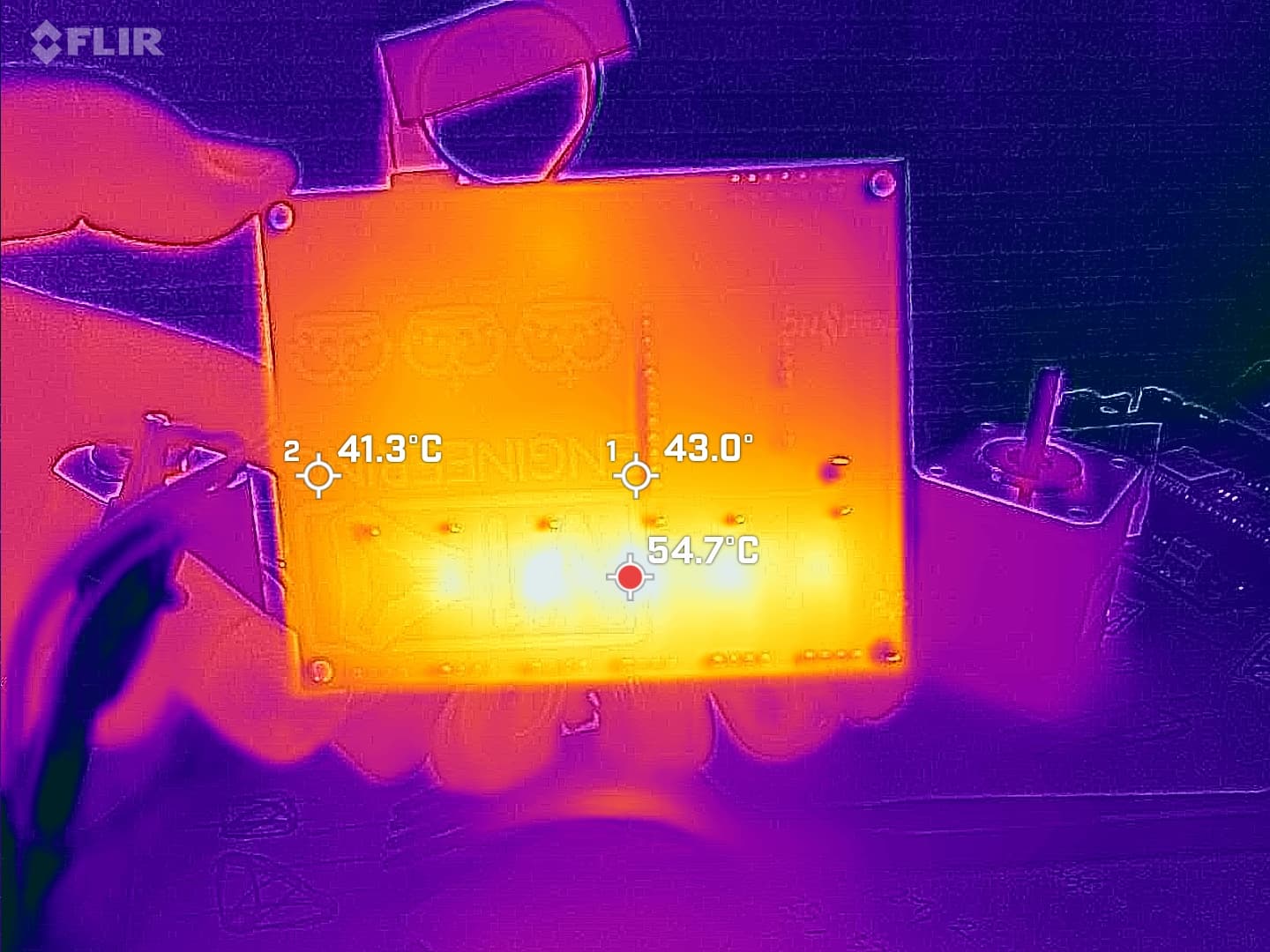
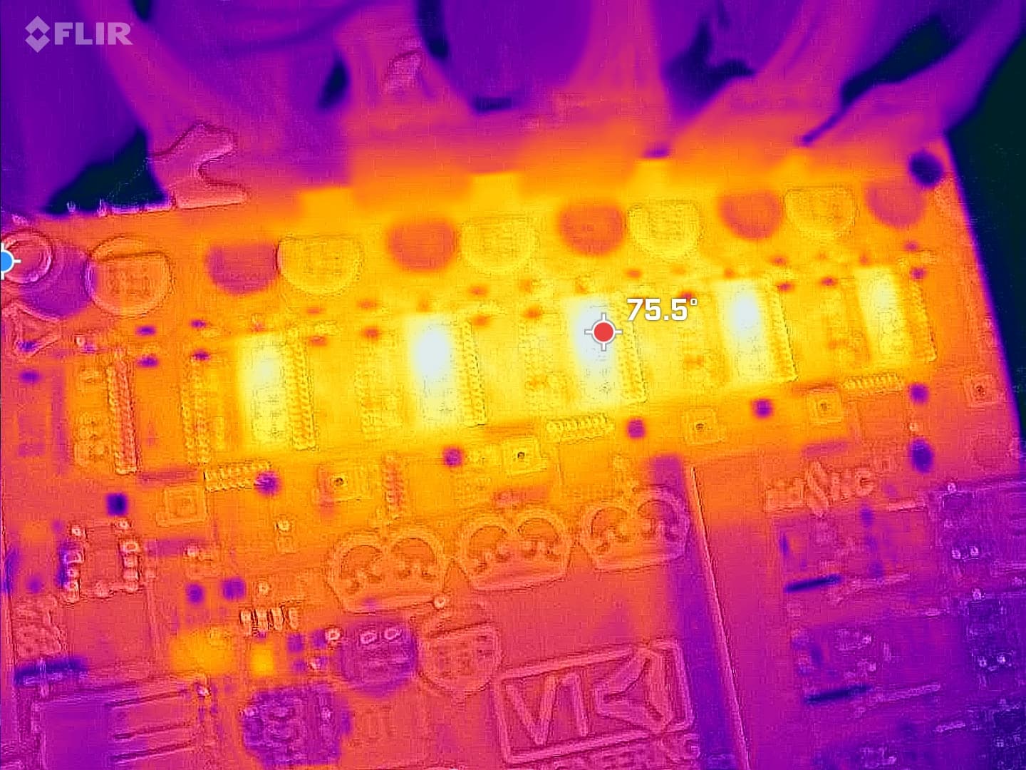
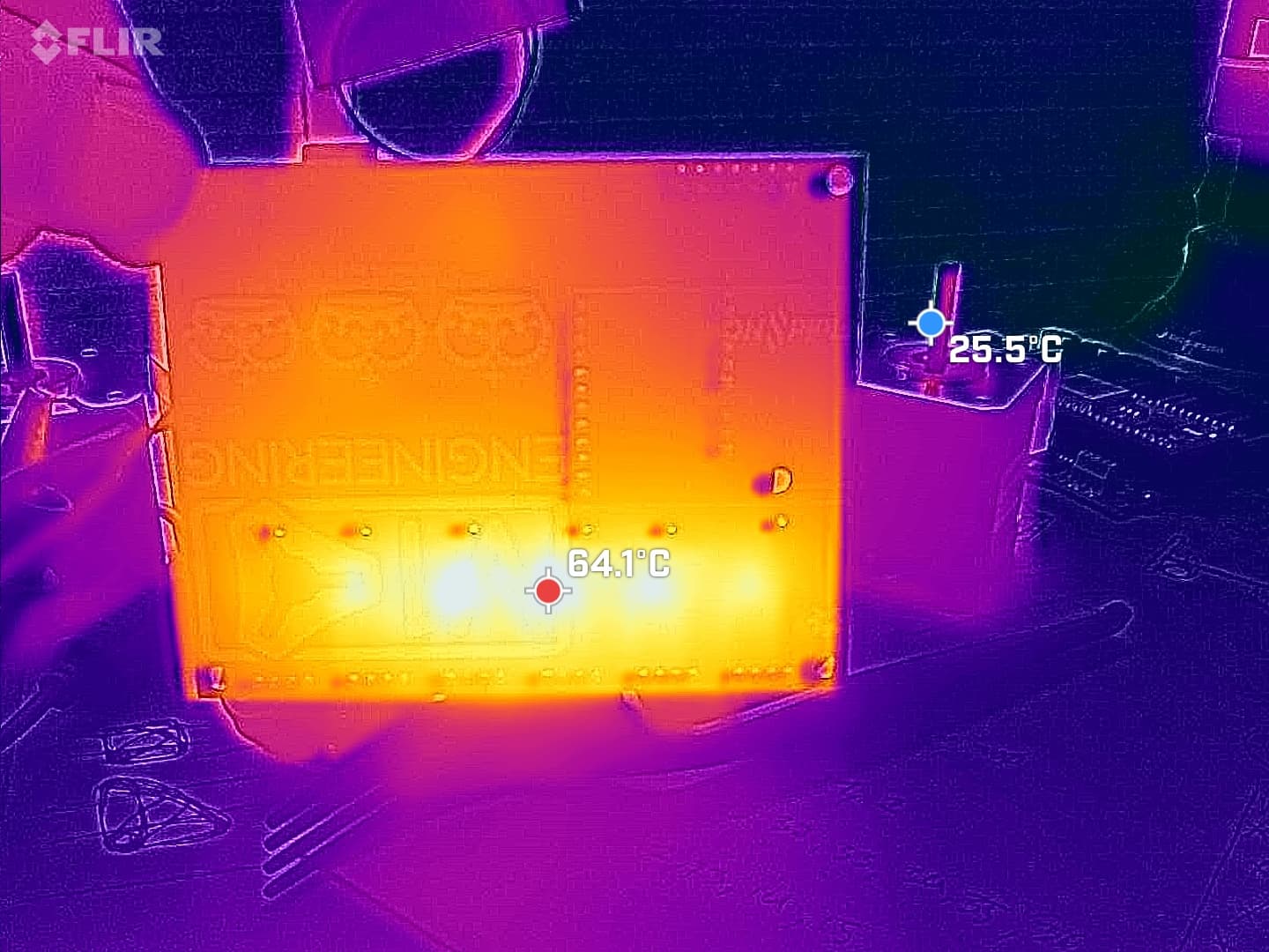
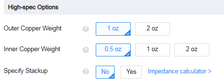
2oz and beyond is remarkably cheap now compared to what it was, while still maintaining usable feature sizes. I’m not sure it’d make a huge difference in performance there because it’s not improving dissipation, as such, that’s a factor of the surface area etc. It would definitely help with spreading the heat out, but that’s already looking pretty reasonable to me… You’d see some extra higher temps around the rest of the board but I doubt that’s driving much of the dissipation, from memory it’s a bit non-linear with temperature delta, so the hot 64C spots are doing a lot of the heavy lifting. I do like working in 2oz, though, it makes some things much easier.

For trying to cool something like this, that’s the way to think of it. You’re trying to spread the heat over the widest area possible. It’s less like cooling a specific thing and more like trying to make the entire board evenly warm…

There is a ton of info out there about dissipation vs surface area in PCBs but it’s all a bit disparate and not the easiest thing to consolidate. I think there are a couple of IPC documents about it as well as some basic calculators. I don’t really have a go-to, I usually just give it a bit of googling. The main issue is that it’s super dependent on installation condition, orientation, etc. It’s also very easily upset by things like splitting a plane with a trace, so it can be difficult to look at a design and go ‘that’s equivalent to X mm^2’ etc.

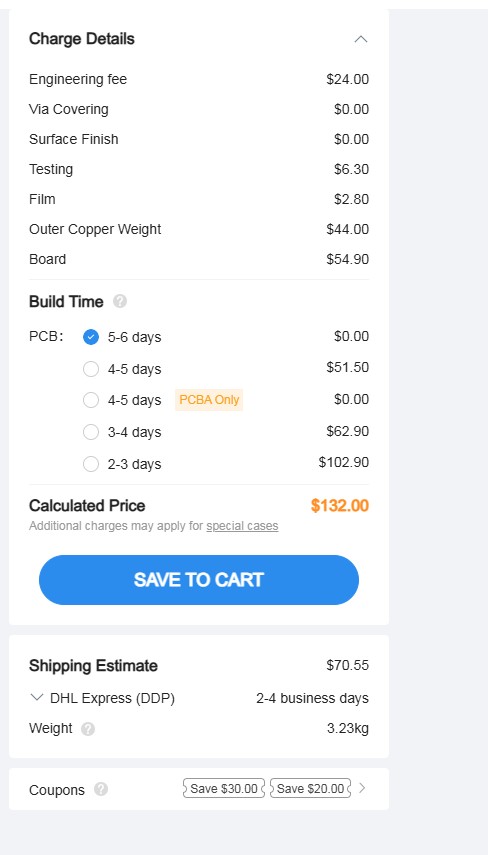
Just gotta run a bunch of quotes, really. It’s often not super predictable, unfortunately.

Never a bad thing, but it doesn’t actually do a whole lot outside the super high heat-flux regions. The vias are usually plated pretty thin, often only 10um or so, so the effect of a ~1.5mm long 10um thick copper tube isn’t particularly strong when it comes to moving thermal energy around. By contrast, FR4 is actually not ‘that’ much of a thermal insulator because it’s thin sheets with a lot of surface area. More vias will help, but if you can get a view of the top and bottom sides of the design together and matched up, I think you’ll see they’re pretty similar thermally. Vias would only help with situations where there’s a thermal differential top-to-bottom.

Don’t let that discourage you from excessive via use, just be aware it’s not really for thermal reasons!

3 Likes

I think you’re also spot-on in that the temperature will rise sharply with ramping any extra current into the design.

It’s also not a bad idea to try get a feel for where thermal cut is. 75C on the hot-spot of the driver package is likely 100+ in the actual package itself. You can get a bit of a half-assed measurement for this by putting a thermocouple onto the package and then insulating the top of it. It’ll make the whole thing run a little hotter, but when you’re measuring the package, you’re actually measuring a point in the thermal chain that goes Die-package-air. If the packaging material was a near perfect insulator but had really good interface with the air, it’d measure close to ambient even as the die was melting. If the packaging material was a near perfect conductor but had really poor interface to the air, it’d measure close to the die temperature. In my experience, it’s a kinda weird halfway point because it’s a thermal insulator but also doesn’t have particularly good thermal interface characteristics to the air and there’s not ‘that’ much of it over the die…

Either way, please bear in mind that the temp on the top of the case is likely a big shift away from die temp. In our bigger applications we use packages that have internal temperature sensing and even that can be ~10C or more away from the actual die temp.

There’s also all the typical application variances to consider, too… Some drivers will have higher internal resistance than others, there’s variance in the internal temp sensing etc. I’d want to leave as much margin as I could there, especially because thermal issues are likely to be a bit of a horror show… Good performance on short jobs but long jobs on hot days randomly shutting down etc. :expressionless:

Thinking about it further, the application isn’t actually that similar to what we deal with in our capacitor arrays… It’s not actually much power, the issue is that there’s no good thermal path to get it out. We’ve had some pretty good luck with using double-sided tape to just stick the entire board down to a sheet of aluminium. A 2mm sheet of aluminium is infinitely better than any copper you can add because you’re adding mm of aluminium vs 10s of um of copper, especially because that copper needs to have traces routed in it eventually…

So that could be an interesting test, as well… Get a sheet of scrap aluminium that’s a similar size to the board and just double-sided tape it down. We do that with multi-kV tuning arrays carrying a couple hundred A so I’ve got zero concern about a 24V board with an amp or two in it! A single stamped sheet of aluminium and a small patch of adhesive tape is something that’s disturbingly cheap in volume out of China, too, so it may be a viable alternative. Could be something just for people in hotter areas, too, or an extra few $ cost for peace of mind etc.

1 Like

Thank you for sharing the experience. I assumed heat sinks are just the right move. Doing what I can with the board is always just a bonus.

On another note, I am not excited about the connectors. I ordered the 5 top 2 pin spring terminals on jlc to see if I like any of them more, if not the gray ones I originally liked are the better option. Those LED wagos I used are great for solid wire but the button is pretty fragile and stranded wire is not fun with it as the button does not really do a whole lot. It is a wedge, I prefer a much larger gate.

Jim, I also have some diodes coming with that order so I can doctor up another board to send out your way to play with.

For 2oz copper, I know this was the approach that Duet uses for their boards, and it appears to work. Genuine Duets using 2oz copper appear to have a significantly reduced failure rate than the knock-offs with the same layout and mostly the same components but 1oz copper.

I do not know the mechanism, but suspect that greater thermal conductivity effectively increases surface area. Duet also advises that the boards be mounted with the underside of the stepper drivers exposed and vertical if no forced air circulation is present.

Of course Duet boards aren’t supposed to be “budget” anything. They’re spendy and they know it. The knock-offs come with heat sinks, the genuine do not. To me, that screams that the heat sinks are cheaper than the genuine’s manufacturing process.

1 Like

The old OpenCNCShield 2 had them as well, one of them did not even latch right. I like the green screw and plug terminals a lot better.
I also didn’t buy the “original” Estlcam board this time because it has static screw on connectors. Would be a hassle installing it. :sweat:

1 Like

Crappy connectors would wreck an otherwise great board. I say keep iterating on this.

Copy. I’ll be ready. I’m toying with trying to build up an airplane-portable LowRider 4 so let me know when you’re ready and I may order another LR4 kit to combine with that board when shipping.

As a matter of fact, I may well do several other portables: a portable MPR&P, a super portable ZenXY, maybe even a super portable MP3DP V5.

I sense an excursion into fancy transforming flight cases coming along.

2 Likes


$0.44 per board for more copper.
Worth it or no, or am I going to have to get a batch and see if there are any noticeable differences?

1 Like

I don’t know, am mainly watching to learn if/how better thermal conductivity increases area for heat dissipation.

Was the 44 cents increase for small batch size. Thought I saw increase drop to 30 cents when seeing what 100 to 200 boards would come out to.

Have you already explored using smaller but good enough heatsinks that get packaged but not assembled? Maslow 4.0 and 4.1 comes with no frills black roughly 9x9*5mm heatsinks, which seems to be half height of the Bigtreetech ones. They’re already permanently pasted to the chips, same heatsink part used for TMC2209 and the brush driver chips. No heatsink on the regulator which was surprise, but I haven’t FLIR’d or checked current draw to see if that’d help anything. I don’t know whether or not Bar is happy with them based on Customer feedback.

Already looked at their layout for ideas?

1 Like

This is confusing to me, it basically doubles the price of the board?