What’s an example of a high power 5V load?
Pulling down the 5V bus will make the system very unreliable.
1 Like
Yeah, not really a lot of high power 5V loads. Maybe WS2812B addressable LEDs but that’s a bit of a stretch. I agree, high power 5V is not realistic.
1 Like
Thanks guys!
I think the 5V is usually for an SSR (which also can be 24V) or wled trigger pins so we should be safe??
There is a lot of new stuff here, I was only going to get 2-3, but if you want a couple I will grab some extra. Chances are very high I screwed stuff up.
The fall back plan in my head for these was just to have two separate circuits, one for the 5V and one for 24V. With this two mosfet config, I can almost just move the voltage selector and be there.
Let’s try this one first I think.
![]()
I have a few boards on the way.
9 Likes
Man, that was fast. ![]()
3 Likes
Boards are done and should hopefully ship out tonight. 5 business days from upload to shipping is so cool.
8 Likes
Look forward to seeing how the new board turns out.
Incase anyone’s interested in learning/sharing similar stuff, Maslow 4.1 CNC controller board with 2x TMC2209 and 4x drivers for brushed motors is being updated over at https://forums.maslowcnc.com/t/what-can-we-improve-in-the-hardware/22430/157, I’ve tried to contribute my 2cts of knowledge while learning how to control brushed motors. Guessing some curious and EE folks here reading this topic might be interested in learning/sharing info there too. Cheers!
2 Likes
Good news----
The new board is here, I made one tiny mistake all, a little hot air and remove the extra capacitor and add a jumper and they work.
As far as I can tell everything works, inputs, outputs, steppers everything.
Issue—
The issue I am having is I have to hit reset to get the webui to load and the drivers to initialize correctly. 24v or USB only, same deal.
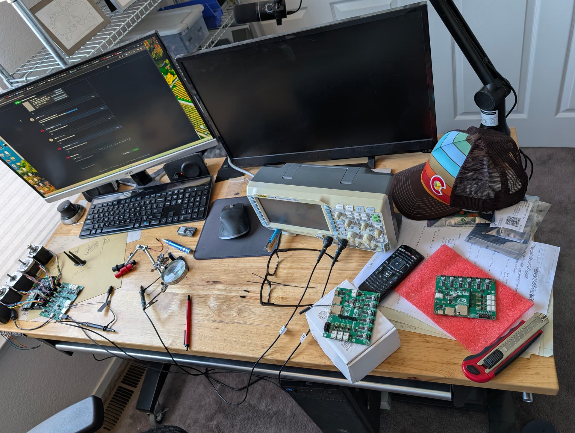
With the scope I have checked the timing of the enable and 3.3v pins on the esp32 and it seems close but I guess not close enough? Let me get some screen grabs to see if any of you can help.
4 Likes
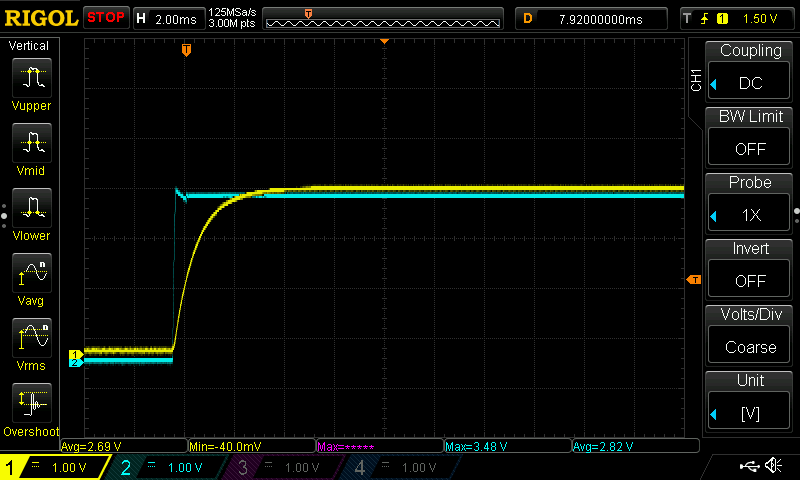
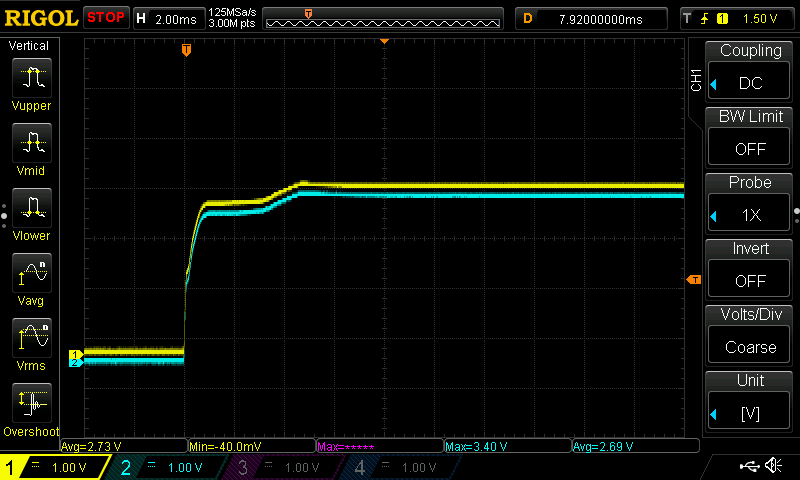
Blue - 3.3v @ the esp, Yellow - Enable @ the ESP
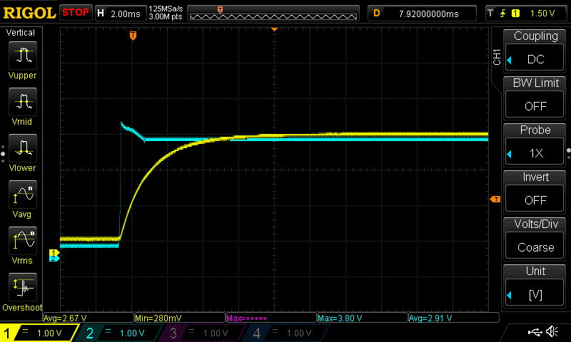
genuine naked esp32
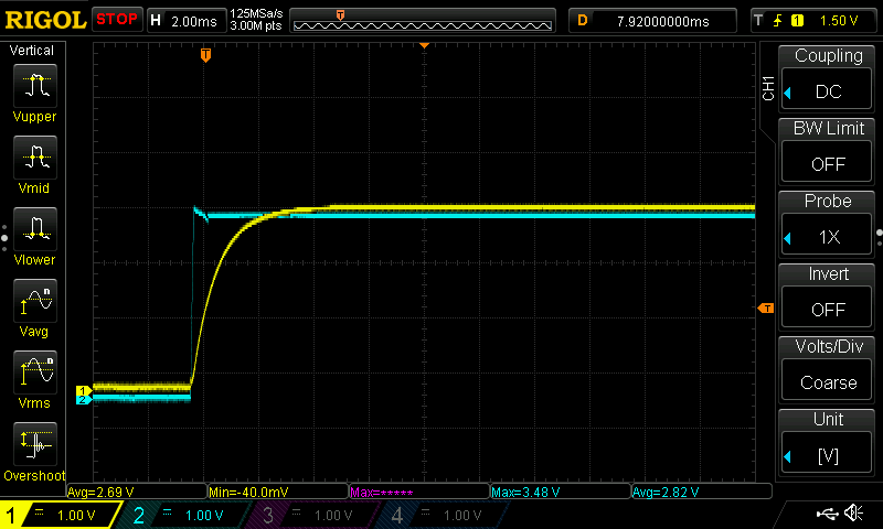
V1 naked esp (I used this for the V2…)
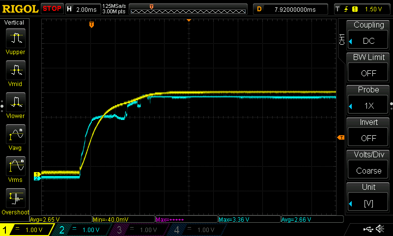
First V2 boot from USB, WTF, maybe a bad probe…
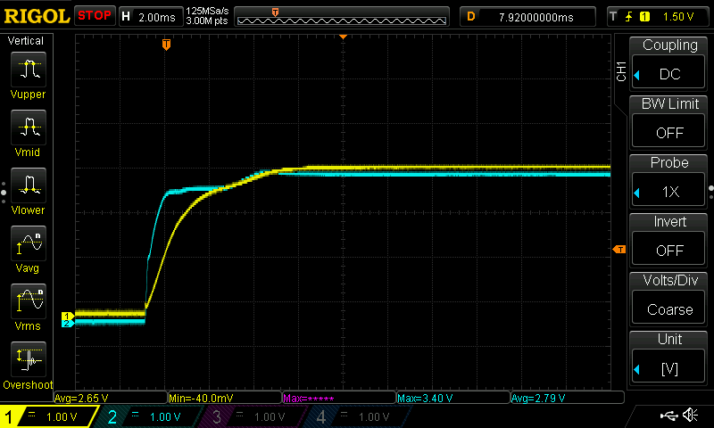
2nd v2 boot from USB, Is this tiny little dip the reason? ~0.2V lag, too much capacitor?
Jackpot boot with v1 esp
2 Likes
Shoot, while the steppers are plugged in and no 24V supply, just USB the steppers make noise and I can feel tiny little pulses. That is new. Even after I issue an $MD
Something is drawing down that power I suppose.
I need to ship one out to you ASAP Jim.
3 Likes
Maybe a noisy uart line?
2 Likes
Okay, USB only somehow the Vmot has 3.77V on it. That is not right. Making progress.
2 Likes
I’m a bone head. The diode is supplying the 5V AND 3.3V power supply when is should only feed the 3.3v.
I need to try and do some surgery to correct this.
4 Likes
I sure am glad you know what you are talking about. I always follow along and try to learn but so much of this is WAY above my pay grade ![]()
3 Likes
I randomly want to throw in that I suggested an integrated ESP for the first version and was told it wasn’t a good idea. Just coming back to say I told you so… ![]()
![]()
New board looks great! ![]()
2 Likes
I still don’t like the idea of it, but it is one of those things that is better for business by saving a few pennies. I still prefer to have everything plug into a socket.
2 Likes