Take a look at the data sheet for that part. I bet you find the block diagram instructive.
How inexpensive are they?
We haven’t even talked about back EMF protection- I bet the automotive part has that as well
Take a look at the data sheet for that part. I bet you find the block diagram instructive.
How inexpensive are they?
We haven’t even talked about back EMF protection- I bet the automotive part has that as well
I love using premade drivers like that. I used to use uln2803 in a lot of projects. It makes a lot of sense in the manufacturing scale I’m used to (1-10).
I mean this seems perfect for $0.25, ZXMS6004FFTA | Datasheet | Diodes Incorporated | LCSC Electronics (okay the 1Amp rating is a little low, but do we really need more than 1A??)
Is the downside just the cost? The upside is added protection (EMF).
Short Circuit Protection with Auto Restart
Over Voltage Protection (Active Clamp)
Thermal Shutdown with Auto Restart
Overcurrent Protection
Input Protection (ESD)
High Continuous Current Rating
(cost meaning about double what a hand built one costs) I understand that is not technically a lot.
Isn’t that a low side switch?
For the way you’re configuring this, you’d want a high side switch, right?
$0.10, ETA7014S2G | Datasheet | etasolution | LCSC Electronics, #C7465500
up to 36V 5A
HIGH SIDE…
1V logic
Still need the flyback diode with that one, it only has 20V reverse protection
What about the ZXMS8xxxx series?
Edit, not high enough voltage limit
What does self limiting mean for current abilities?
Just keep the flyback diode?
So maybe the advantage of the DIY method is you can tune it the exact way you want if an off the shelf solution is not readily available.
Hmm, alright I am going to take a break and go play in the river.
DIY does let you design for your application.
I have only limited time to sort through, but I bet there is an automotive/CAV/industrial part that is a good fit.
Look at OnSemi NCV8450 as an example. $.46, though may not be in your supply chain.
Block diagrams are always instructive.
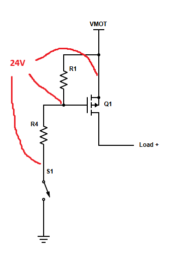
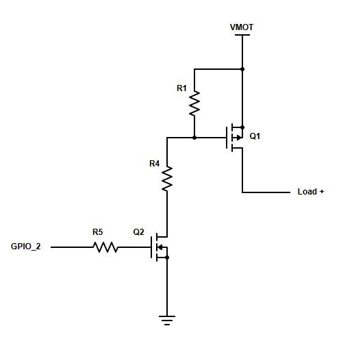
When Q2 is open, then there is no path to ground, and both spots are 24V and therefore Q1 is off, meaning it acts as open circuit between 24V and Load+, so the load is off. There is no path to ground on purpose – the circuit is floating relative to VMOT and the absolute voltage (relative to ground) is not playing a part. Floating is fundamental to a high side switch and a big part of what makes it annoying compared to a low-side switch.
Supporting both 24V and 5V makes it nontrivial because you have to pull hard enough but not too hard over a wide range of input voltages. Using a part that supports a high Vgs(max) helps. Otherwise it might be hard to find a good ratio. More complex circuits can handle the wide range but it pretty quickly gets harder to understand.
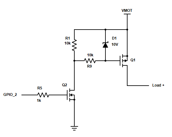
As an example, if you add a 10V Zener diode then you can keep using a mosfet with a 12V limit. But the intuition of how this works is more of a challenge.
Voodoo ![]() , So if we were not trying to make a voltage divider R1 seems useless, it floats either way if q2/s1 is open.
, So if we were not trying to make a voltage divider R1 seems useless, it floats either way if q2/s1 is open.
Thank you. I do enjoy learning this stuff. Such magic to me it feels like I am learning a spell.
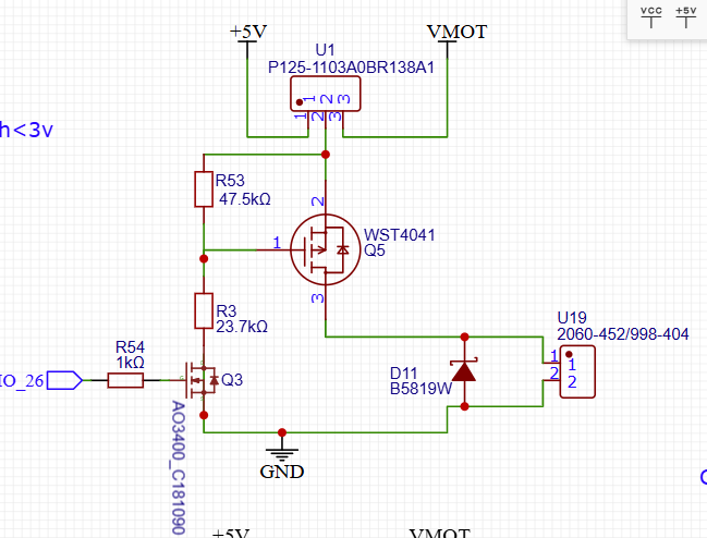
So we go back to this one, I think I have all the right parts or can at least find them.
The flyback diode protects it to a large degree, Jim there are other things you think we should protect against beyond that?
That divider gives us 16v and 8v for 24V input, 3.33 and 1.66 for 5V input.
VGSth for Q5 is 2.2V so we are good?? The 5V side still pulls up with 3.3v and when Q3 is closed there is a path to ground (pulls low).
Q5 - WST4041 | Datasheet | Winsok Semicon | LCSC Electronics
How do you current limit when someone shorts the output?
Like a small resistor, or should it be more sophisticated?
On second thought, it’s fine as is. The FET can be changed easily if you blow it and are inclined to repair it, otherwise the board is really affordable to replace.
I mean if we add another $0.05 component and it could prevent that I am in. I am not sure if the high side vs low side is any different, I don’t think we had and shorting issues on the 24V outputs.
This is all well above my comfort zone and I am reading as much as I can. Most still seems like a lot of magic to me. I do seem to understand the basics but as soon as the specifics come it seems like a never ending rabbit hole of conditions for each component.
P.S. the resistors in the voltage divider above are 1% resistors so the voltage should be fairly stable. (proof I pay attention)
If you can find a way to add a fuse for $.05 then go for it, otherwise it’s fine.
Are you going to do a test run of these at some point? I’ll prepay for a couple in that first batch.
I think this is good enough but not great.
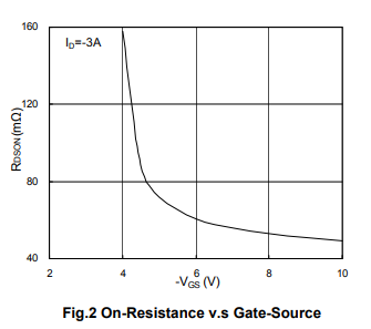
The reason it’s not great is the mosfet prefers to be driven with higher voltage delta on the gate to be fully on instead of just partly on. If the voltage is just a little above the threshold, then it will be on but it will have some resistance.
When drawing a lot of power, the 5V could droop and the mosfet could get hot. It is probably fine.
I can walk though the ‘voodoo’ approach if you want, but perhaps build it with the voltage divider first and see, before over-analyzing.