Still thinking about the switchable voltage P-channel FETs.
Also a reminder to put pads to allow breaking out the stepper driver signals- with appropriate protection this could allow folks to use external drivers.
EDIT- scratch that. Now has the drivers integrated.
Able to share how board dimension are currently looking, are you expecting same or smaller width-length? I appreciate everything is subject to change, and/or you may not be ready to reveal details yet.
Questions I have: What do you do if a driver blows? And Don’t you think it is a step backwards not to be able to connect external drivers (you somehow couldn’t with the Jackpot either), wouldn’t it be better to enable this or is this not the target audience?
Speculative guess partly based on vague recollection of previous topics/posts… Thought board is coming with 6 integrated drivers, effectively a there’s spare driver that most will never use? If so, they can self repair by modifying default stepper config. Or, maybe 6th stepper slot ends up being unpopulated Pololu headers that someone can purchase UART driver if/when needed because they need extra axis, or 1 existing integrated driver blew? Or, maybe this is a 5 integrated driver board to minimize cost with no redundancy. They just buy a new board (similar to Maslow CNC and others). Maybe there’ll be a small trade-in discount to salvage root-cause quality/usage issues?
Sounded like this board is right sized optimized for vanilla MPCNC/LR4 builds, this is an additional cheaper easier option for Makers to choose if they prefer lower cost, rather than maximum flexibility. Ryan said O.G JackPot will still be available. From the perspective of Maker considering whether to invest in my 1st/2nd CNC… I’d personally appreciate an additional cheaper option.
BTT have too many options to choose from imo.
TB6600 externals can be connected to JackPot right? But are you asking about SPI based Pololu or external drivers e.g. 10 A rated 5160T modules? SPI would need different PCB design, or significantly hacked existing PCB. But would FluidNC support also still be needed? (I’m asking, I’m not asserting, I only took a quick look at FluidNC discord/docs, will look again later this morning depending on responses from folks…).
Not properly unless additional ESD protection is added alongside the external drivers.
I’ve tested it and it can work for “dumb” external drivers. (Dumb as in no UART, not dumb as in no controller smarts) so you could for example run closed loop stepper controllers on Jackpot but not say 5160s.
Edit: this is why I still waffle on my thinking about pads and cut-trace locations on the board. Most users would just buy a new board or use the spare driver if they blew one. I would attempt repair or retrofit or even mods. But I’m not the target audience of the streamlined jackpot derivative.
There are several external driver fluidnc boards out, you save some money not paying for drivers and the plugs to support them are already there, Corgi is a new one. There is not much room to spare and am I mistaken by not seeing this as a common want? Most external driver suck, they have a 0.5v step in current adjustment, that is almost useless in most <nema34.
If there is a need for an external driver board I can easily take off the drivers that are on this board figure out what is required to support externals and save those users even more money. I don’t think paying for 5 drivers and the support components is a wise idea.
Correct, or rotational axis.
I am not sure anyone has ever blown a driver. We have had a couple boards with a bad UART line or something but I do not think popping drivers is very common these days.
The bottom line is this board costs significantly less time, and is hopefully more robust. Time is more valuable than the 30% cost savings. This allows me to do other things than order, and assemble hundreds of boards. This also allows me to much easier ship a manufacturer direct a complete board. The Elecrow jackpot 1 is a great option but then you need to track down your own GOOD esp32 and Good Drivers. As for being more robust a issue we have seen pop up a lot is broken power connections and that causing random brown outs. This is probably one of the largest issues we see, that is fixed. You all wanted external antenna, also fixed. My goal here is to make a better jackpot not really an entirely new board.
So another EE question. Since this is open source and easyeda is free software, are prefixes really necessary? If you are doing anything to the board, you will have the complete source open and available to figure out what a component is. It is so much more clean without them.
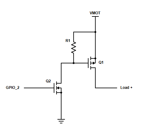
The 10k - 100k resistor divider by itself would put about 91% of VMOT on the gate if the GPIO were not connected. At 24V this would already be 2.1V below source and it might turn on by itself.
When connected to GPIO_2 and GPIO_2 is low, the gate will be dragged down to near GND and it will turn on even if the high voltage is 5V.
When GPIO_2 is high and you’re using VMOT, the resistor divider will try to feed it backward since 91% VMOT is higher than VCC and it could kill the ESP32 or in the best case there would be an internal diode to let it feed back to VCC with about 2 mA. Or you could add your own diode to prevent GPIO2 from being driven too high.
But either way, in the best case, the gate voltage will be only a bit higher than VCC and much lower than VMOT and the MOSFET is still on.
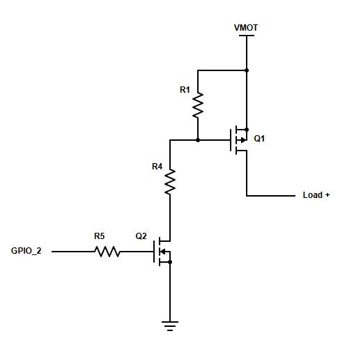
I think you might need something like this as a starting point:
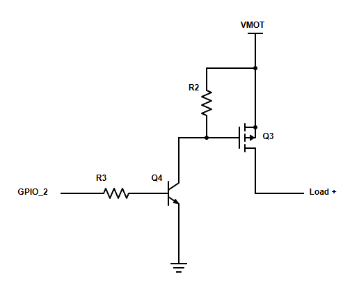
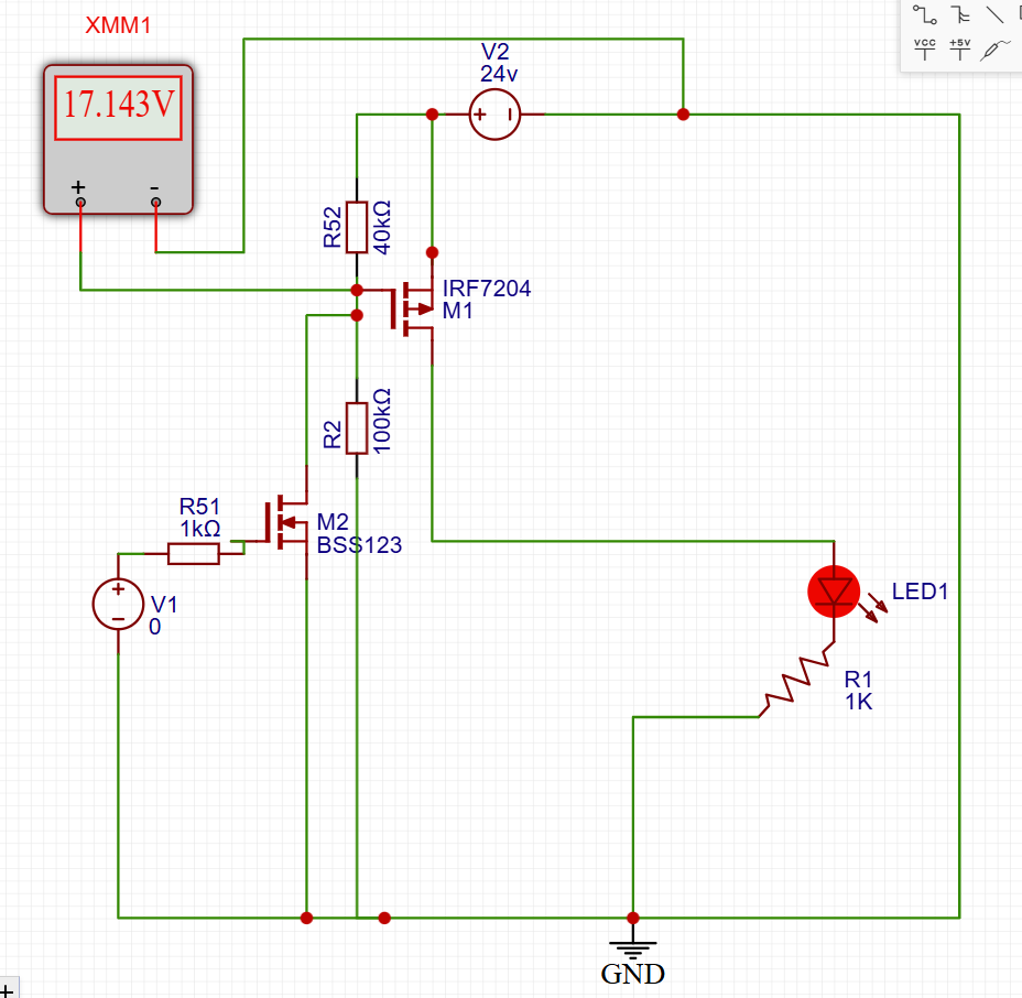
Okay thank you Jamie. That got me nearly there but I could not find many mosfets with a Vgs higher than 20V so I had to use a voltage divider. Looks like I can get 17v or 3.5V that should work just fine with a Vgsth of <2V.
Oh, I didn’t realize the Vgs(max) was an issue but I see what you mean. I suspect that your circuit may still have a problem because when M2 turns on, the gate of M1 will effectively be shorted to ground and you’ll have 24 volts between source and gate. (Your measurement is between gate and ground, not gate and source of M1.)
When Q2 is off, the gate and source of Q1 are the same voltage, and so Q1 is also off.
When Q2 is on, the gate of Q1 is not short circuited to 0V, but is instead divided down by R1 and R4 for a fraction of VMOT.
Unfortunately, 24V and 5V are quite different and 40k / 100k will produce 40/140 * 24V = 6.8V for VMOT=24 and only 1.43V for 5V (between source and gate of Q1).
If you swap them so 100k is between source and gate (R1 in my diagram, R52 in yours) and the other one is 40k, then you’ll have 17.1V when using VMOT=24 and 3.57 V with 5V supply.
If you needed to handle 48V and 5V then we might need something more sophisticated, but as it is now, I don’t see a reason it wouldn’t work.
Dam you are good. that actually leads to a question I do not understand. That part is why I made it that way…but I do see you are correct now. So In your most recent diagram, I do not understand how R1 is a pull up. If Q1 is open, AND Q2 is open where is the ground coming from. Or does this mean with no load on it there is no pull up so this is all a waste as the is 24V at LOAD+?
I get that it is the difference between the two pins but there is no difference if there is no path to ground??
The other way to think about it is if the difference in the pins is 0v and 24V what the heck is R1 doing in your diagram?
So I guess that shows I don’t know how to use a sim. How did I get that backwards?
While doing all of this they do make a single chip for this exact thing, high side driver, mostly used for auto stuff. They are not too pricey either. IT is basically all this built in one with a few features added, some even have a tunable output.
Okay, that part I get, but if there is no current flow either way what is that pull up resistor doing? In my head I see it as there is now 24V on the gate and source, so it is still Zero?