Working on the bed for a little bit today. The build plates and heater came in. discovered two small issues.
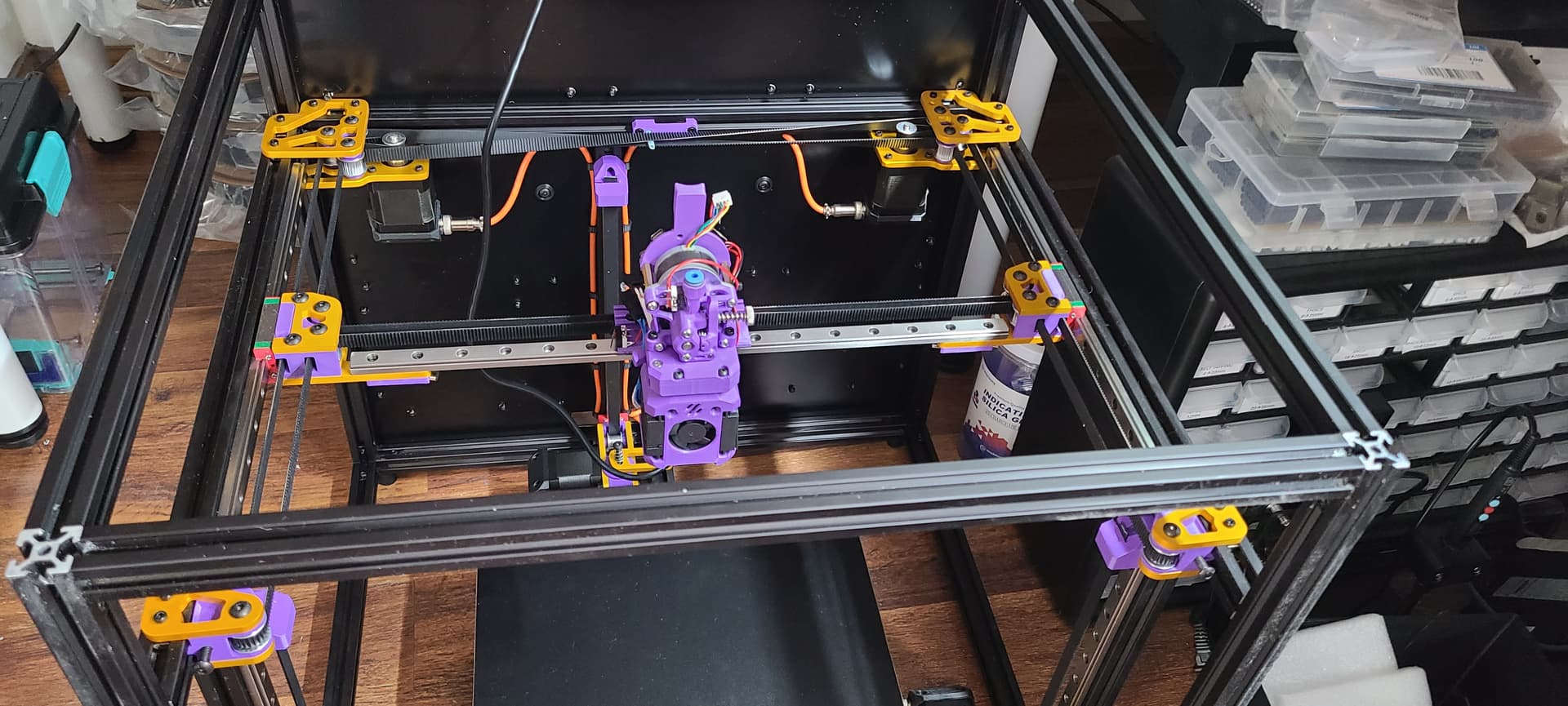
The Dragon Burner hangs down much farther than the H2 I think. Wondering if the Fusion model can account for that in measurements when you use the parametric items for the x and y offset for the nozzle? This is not a huge issue as I sized the printer to do 250mm in Z and will still have at least 200mm when all is said and done.
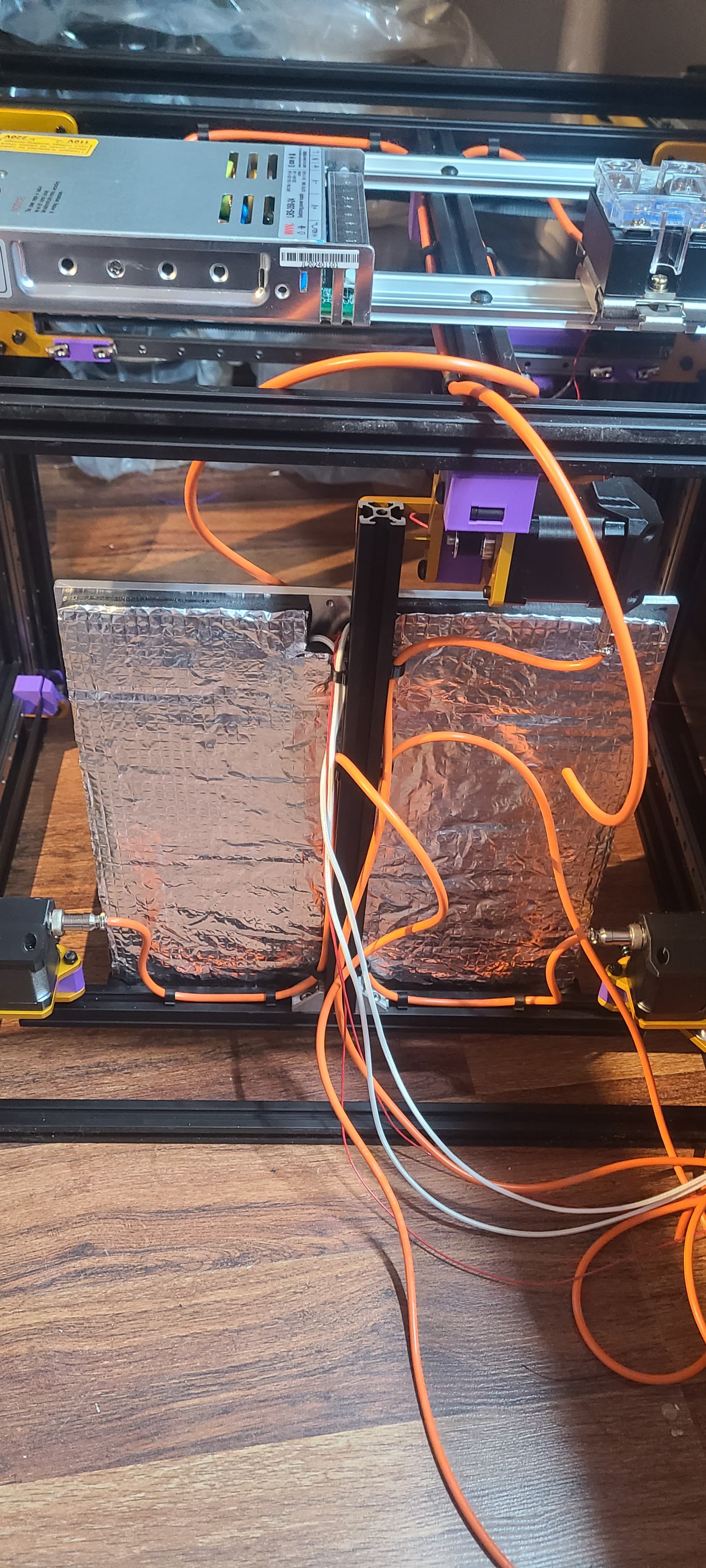
Having the nozzle centered on the carriage causes the bed to be centered in the machine. Again not a huge issue EXCEPT if you had decided to use a full 300x300mm heater. The center bolt on the back of the bed is dead center on the plate and that is where the wires come out. I am using a 280x280mm heater so I offset it forward to give me clearance for the wires. I am using silicone spacers to mount the bed but if I changed that to something else it might be adjustable some.
The chances that I am using the FULL depth of the bed are usually pretty small and I think that there will be enough heat transfer to the excess section of the bed plate that I wont notice it. I need to get one of those FLIR cameras sometime soon.
Mine on my V5 are printed TPU and have worked well. I was able to make the back one shorter to make up for the fusible link thing in line with the bed heater
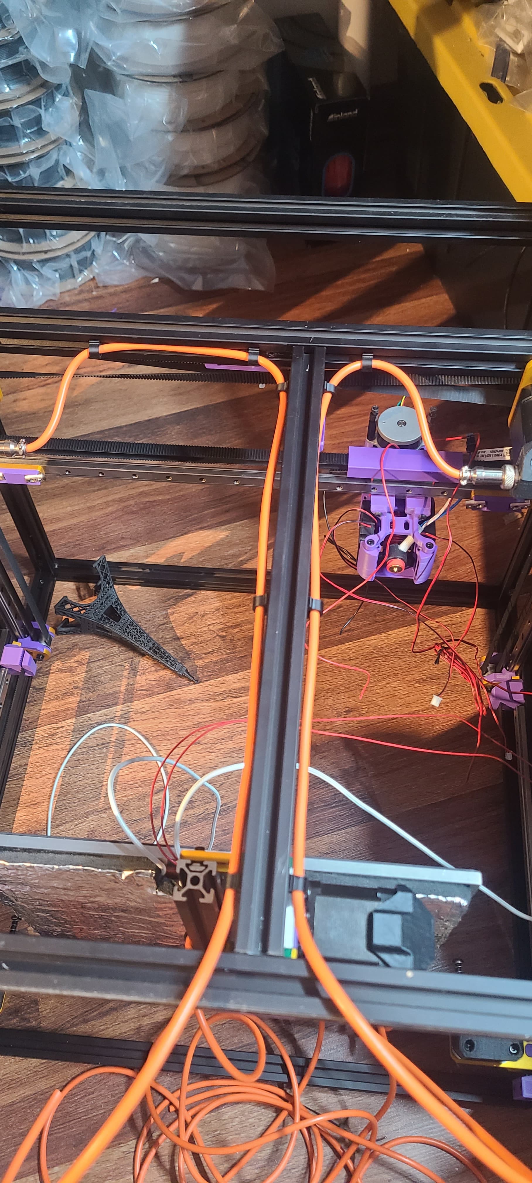
More work today. Printed cable clips for the wires. Also put the bed together!
I think I learned some stuff about MIC-6. I bought a piece that was listed as “mill finish”. it is pretty flat but not perfect I expect that that will not be a huge issue as it is pretty close with my crappy ruler being used to measure
Put the Keenovo 600W 280x280 120V heater on and wired up the thermal fuse. I was a good boy and actually put the insulation on that I bought for the V4 and never used!
Had to order some 10x15 cable chain for the bed connections as the versions I had either did not fit all the wires of did not bend tight enough to clear the bed bars and the projected bottom.
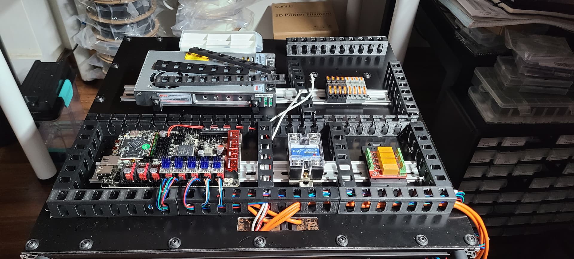
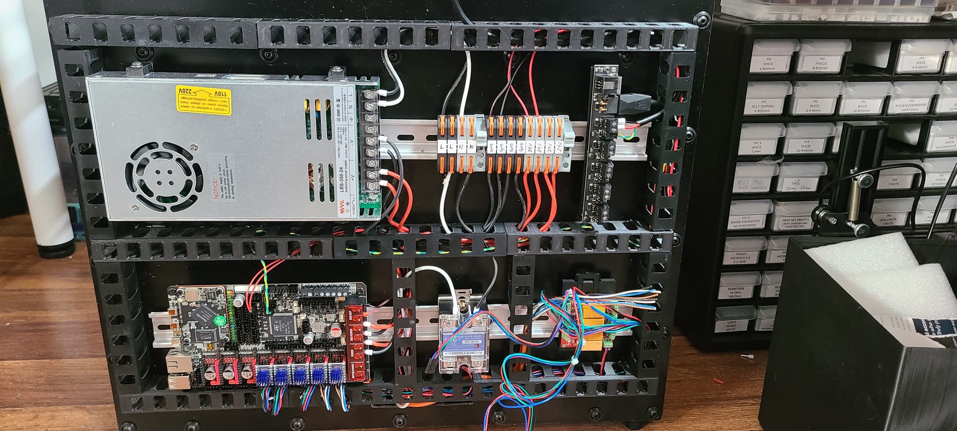
Added the DIN rails to the back. The plan is to eventually put panels all the way around but I want to get things up and running to test out the hotend. Wondering if @orob or anyone else has a DIN mount for the Z brakes board…
I used some silicone mounts I had on hand. Just moved the heater forward a bit and it worked great. The front mounts needed a little trim to clear the bed heater but it is all super solid!
I get that! I went with a full size heater lol. I had to use my thermal camera to see where I could trim a little bit to make the screws clear. The TPU mounts touch the heater but they havent cared in the last year of use.
I like those motor caps. Super clean build. I haven’t started my next build yet. There is no din rail mount for the brake board that i know of yet. You could make one… Or maybe I could.
These. different sizes for different cables. So far the .250 ones have fit both my orange wires and the bed heater and thermistor but I still have a ground wire for the bed so I may have to make one a little bigger.
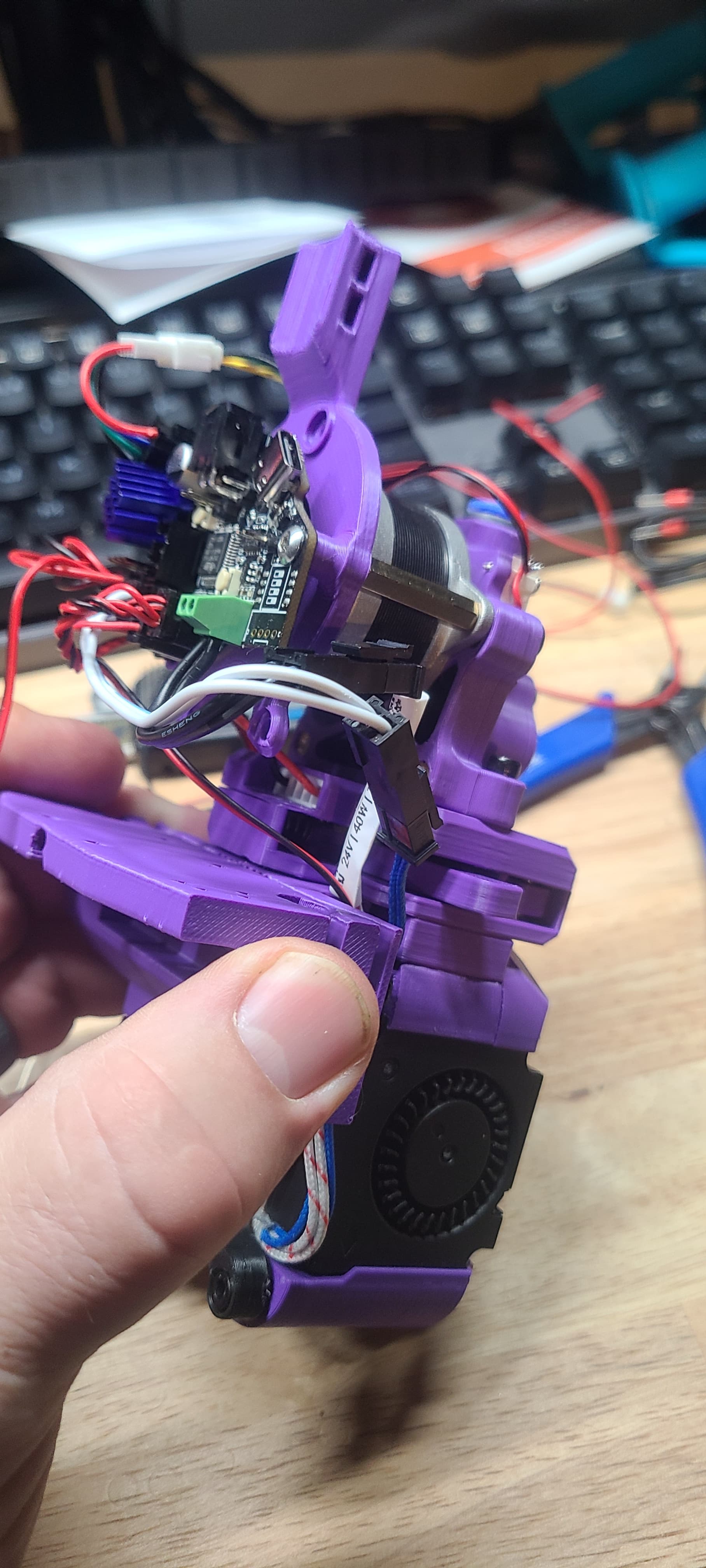
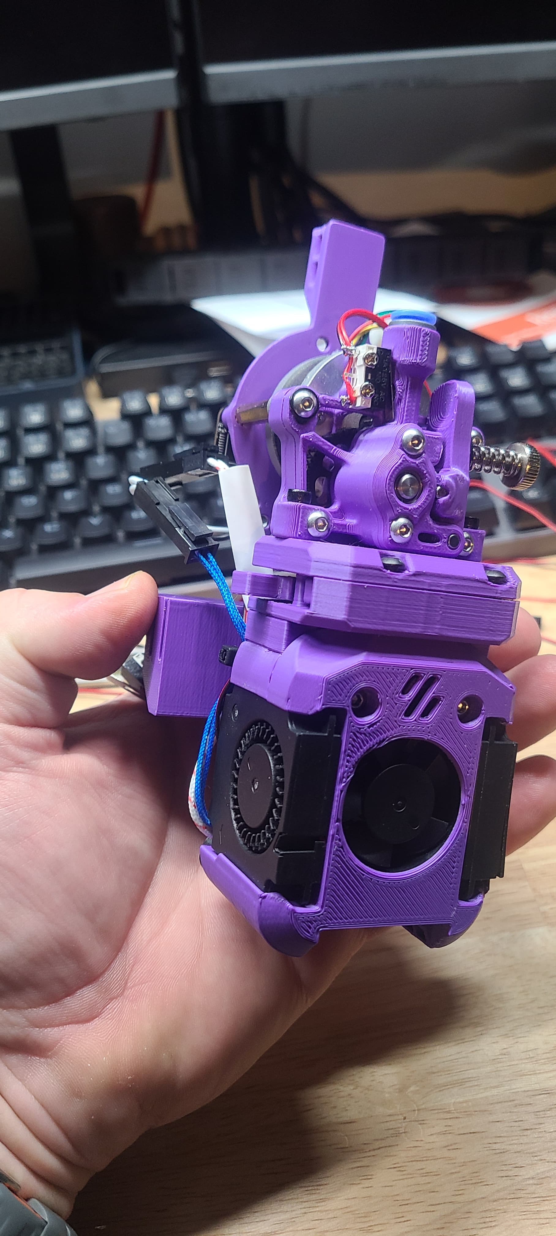
Was working on wiring the toolhead to the EBB36. Let me tell you… putting 3 wires into a single pin requires the strongest cheater readers you own!
One thing that DID occur to me was that the discussion we have had off and on about tool changers was that the x endstop will be an issue. It is connected to the toolboard so we will need to find a way to offload it to the frame somewhere.
Safe Z homing exists… is there a safe x homing that would allow us to put a stationary switch on the frame, home Y, then move to a spot to home X?
Has anyone used sensorless homing on one of their machines? Was thinking that putting it on X and Y would be useful for a couple reasons.
Less wires to deal with
less pins required on the toolhead when using a can board and dual filament sensors. Right now I need to use 3 pins and the EBB is the only option. The Mellow board only has two pins available but has a far superior can bus connection.
Would allow for an easier transition to toolhead changes.
It is less wires but with CoreXY from what I understand it is a little harder to tune. The other downside is it is not accurate enough for power loss recovery if you want to try that out. It is possible though.
Input or output either way. The most important thing is that the wires go straight thru color for color on both sides of the board. The jumper selects between shorting only one or both motor coils. One shorted is loud, both shorted is more quiet. See which you like. Originally it was to only short one coil, but it was easy enough to short both so i made it an option.