Just starting up a new thread to cover the full build of the machine. This may take a little time as We leave on vacation to Mexico for a few days next week.
The Plan:
Build a V5. I will be using blind joints at the connections as I have a really good way to square the ends up (see my other build thread). I will probably add the panels at a later date when I get off my ass and finish my LR3.
The impetus of this build is because I built a TradRack MMU unit and needed a few extra things on my toolhead. According to @Jonathjon’s excellent write up and my reading about MMU’s the software to use is Happy Hare and all the stuff I read says it works best with filament sensors above and below the extruder. Filament cutter at the toolhead also makes life much easier.
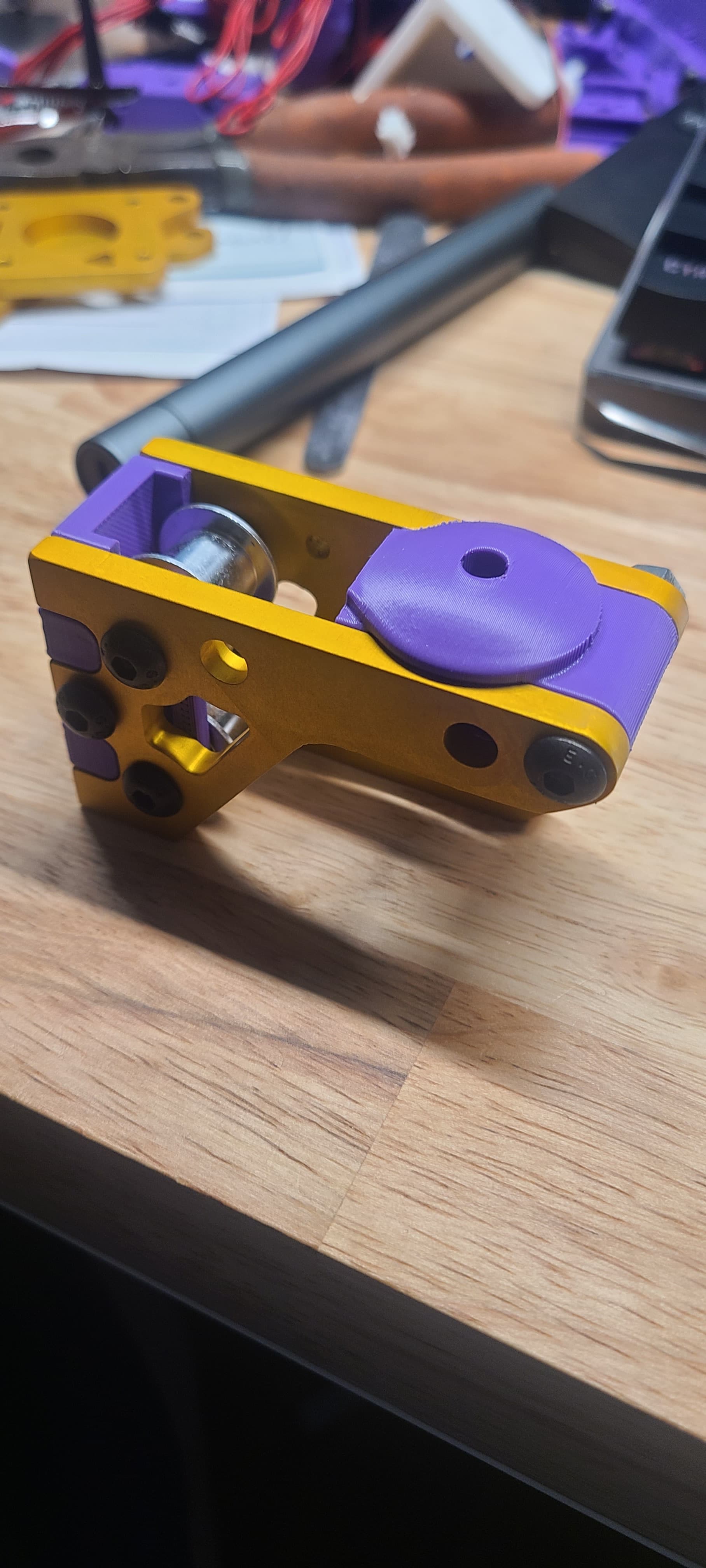
As I have no way to retrofit filament cutters to the H2V2 Revo on my V4 I started looking at alternative toolheads. See my Odd Idea thread. First option was Stealthburner and the latest is the DragonBurner. Dragon burner is more flexible, lighter and has better cooling than the stealthburner.
Mounting it to the machine opened up a couple other interesting ideas concerning where the belts are run (front or back). I have all the core parts to mount the DragonBurner setup in both configurations. I want to run tests on both setups to see what the difference in nozzle distance from the bearing centerline makes.
I cant wait to see a V5 printing with a Dragonburner toolhead! This will most likely get me off my butt and swapping my V4 over to V5 lol. Its been a GREAT printer, but the V5 is just so much faster and better in a lot of ways. I am glad you are building a new one instead of just swapping though. Then you can see the difference first hand. And when you get ready to switch your V4 over to V5 you’ll be able to do anything you wish you had done differently the first time LOL
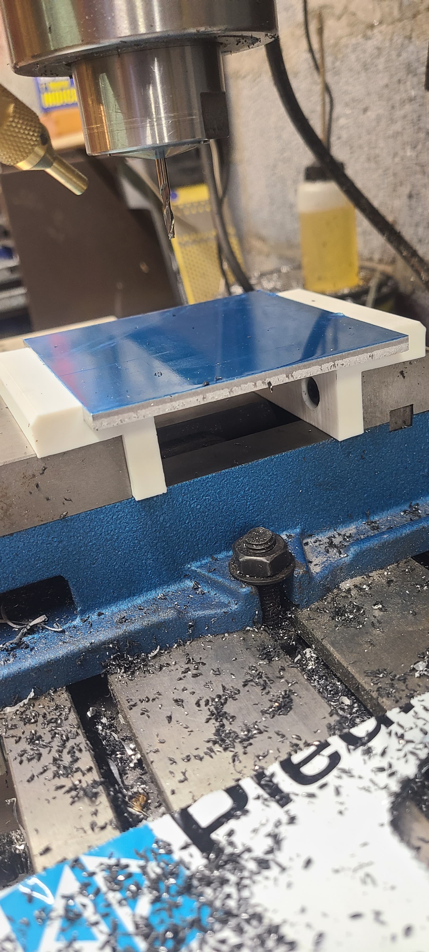
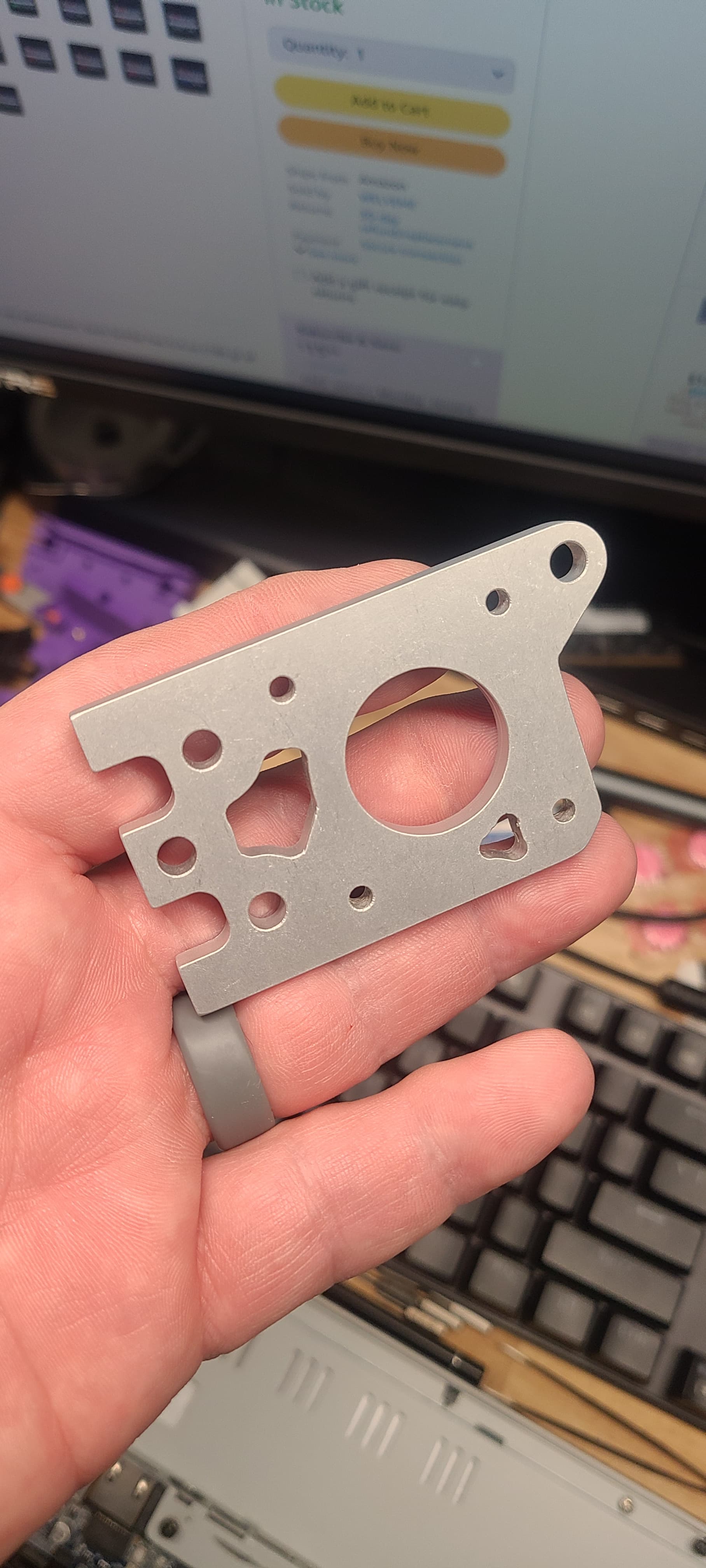
Discovered that my Mill Vise is only 3 inches and the pieces of aluminum I got are 4 inches. So I played with the mill as I have not used it in a VERY long time with some ACM scraps I had on hand.
They came out nicely but are only 3mm. I can use it but then it just wont have that polished look to it. Looking at new vises now. I wish there was a way to put new jaws in that extend the height and holding capacity… I am sure they are around but would need to be made. Think a 3d print will hold up?
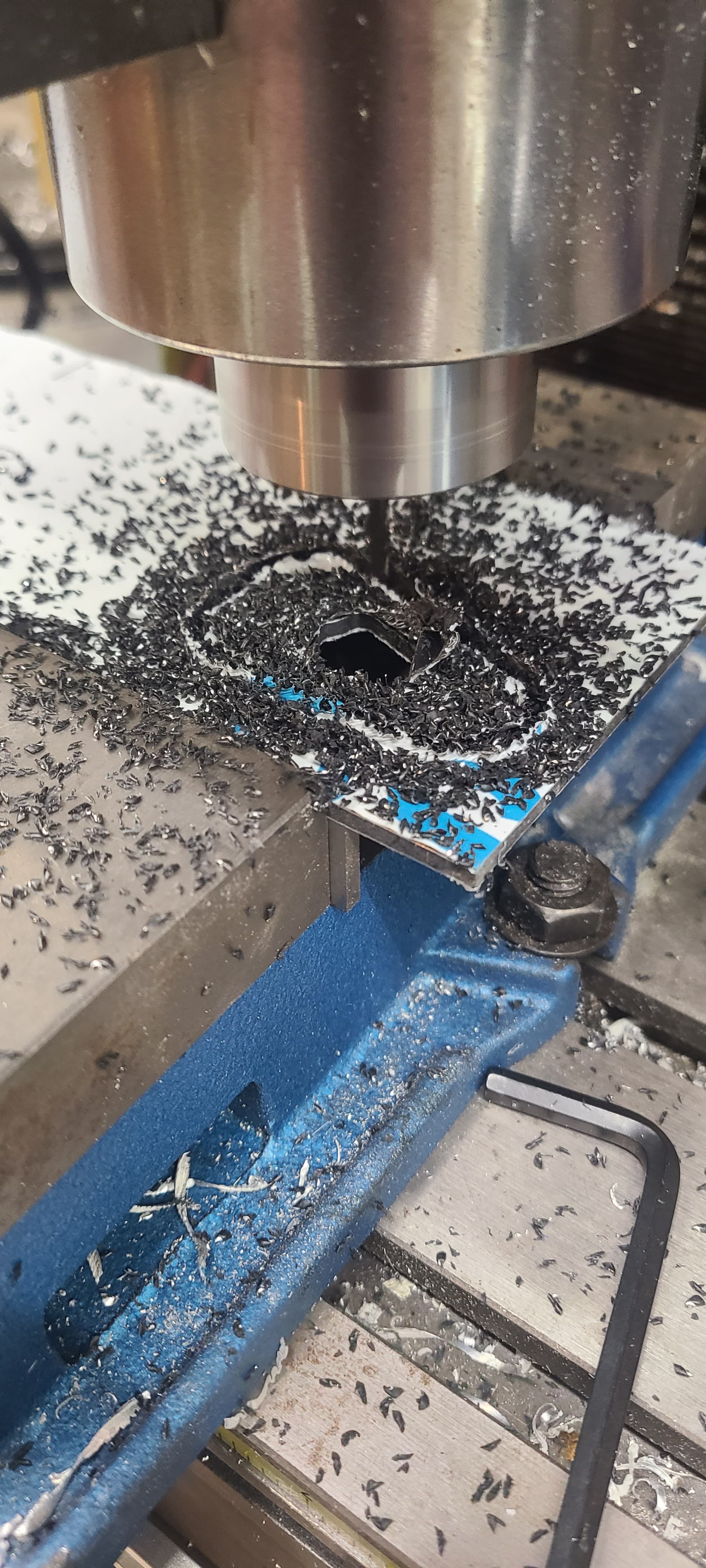
After some starts and stops I have the mill running. My plastic jaws have worked like a charm. Only issue I have is that I have had a steep learning curve on the aluminum milling. Unlike the routers, I have a top speed of 2500 rpm on the spindle.
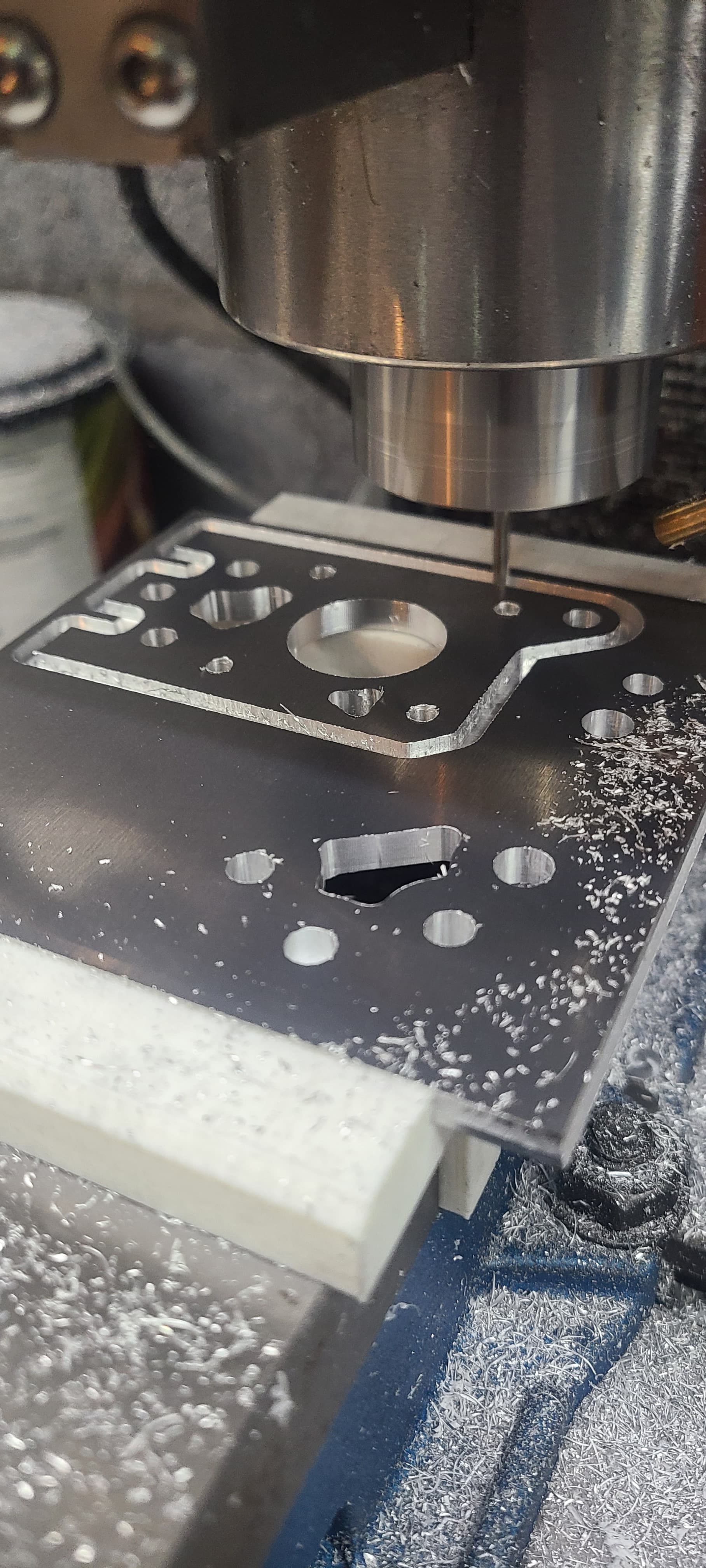
Settled on 500mm per minute and .1mm DOC with spiral lead ins. Leaving .2mm in roughing and a full depth finishing pass. Triangle holding tabs limited to 3 on a part and moved to flat spots.
Cleanup is relatively easy as I have a vertical metal bandsaw and a 2x72 belt grinder to do it with.
I discovered a few things. I have a mister setup and coolant for it. The issue I am having is the coolant makes the chips clump up and it damages the finish. Just using air to cool and evacuate chips now.
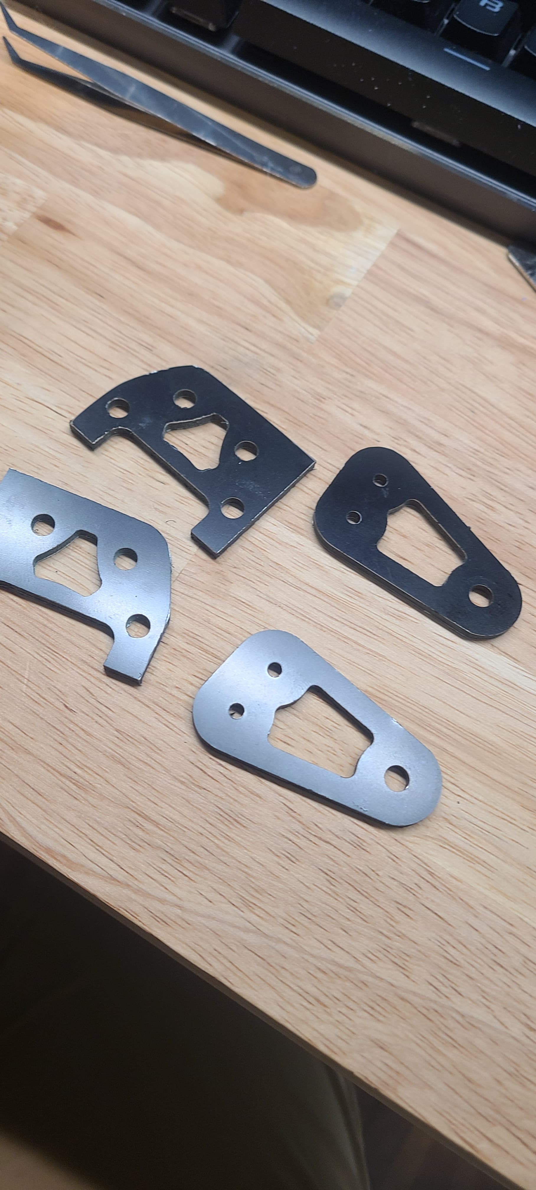
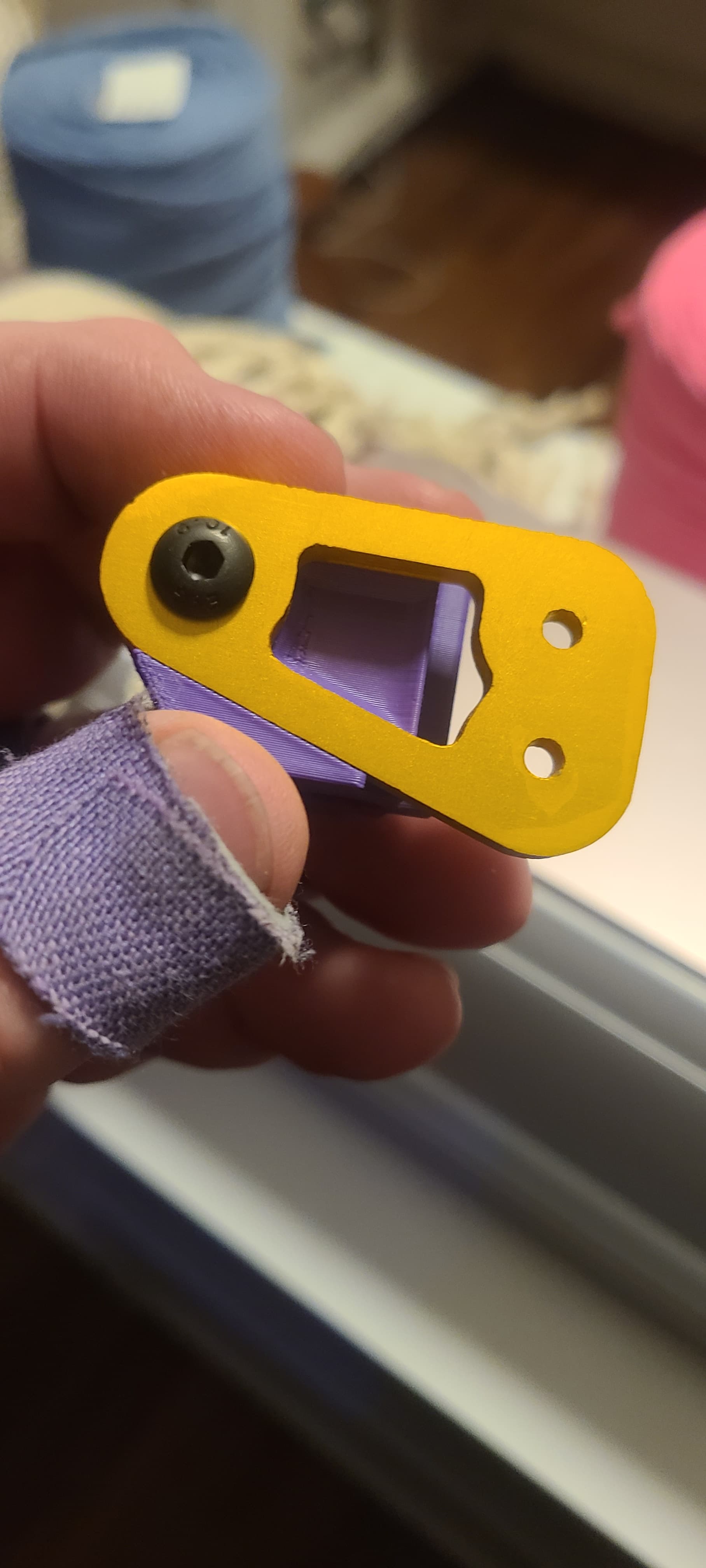
After cleaning the edges up I have been running them in my brass tumbler with a combination or walnut shells and hydroton balls. Seems to do a good finish!
Went out and picked up supplies to try some annodizing. This is seriously yellow food coloring…
Please make a write up of this and how it turns out. I would like to give it a shot just haven’t had the time or patients to figure out the best way forward with it. A small batch set up would sure be nice for doing some LR4 XZ plates!
These look great! The tumbling left an amazing finish.
I originally came here to say that the dragon burner has been used a lot for the Voron tool changers, so I think that’s a wise selection. They do have better cooling also.
Working on the printer today and getting a good inventory of parts. I have 4 20T drive pulleys and 4 16T drive pulleys. Obviously I can use them but will there be a noticeable tradeoff in resolution and if so which motors should get which?
Also, I am short 1 stepper (have 4 that @Jonathjon left in the LR3 parts to use) Wondering if putting 0.9 degree motors on the XY axis would be an advantage.
I don’t think there is an advantage, I have one printer running each kind. If you want to try I have some higher end 0.9 I can sell you at cost. I was hoping they would solve the ripple issue but didn’t.
Curious how 0.9deg steppers work out, Prusa seem to like them (I’d check out their stepper config if going down this path). Recently bought 5mm rods, but haven’t installed, idlers fit more smoothly on the 5mm rods than M5 bolts, maybe that doesn’t matter when belt is under tension. Am still seeing (V4) belt catching on teethed idlers, so have been wondering whether to ensure smooth idlers are last pivot points the belts pass before reaching the core (would need belt oriented right way for this). Stuff like this is partly why I haven’t started my V5 yet. Am also contemplating larger teeth count pulley based on what some other printers are doing.
Don’t like playing this guessing game, ideally, I’d like to measure and directly fix most significant vibration cause(s), maybe using techniques like this…
Any suggestions folks have for open source Motion Amplification and/or vibration detection and/or similar projects are appreciated?