So in the notes for the Tool Mounts it clearly states to print with PETG or “better” I would almost always say ASA is better ( i normally run my theatre parts in it, and my AMS is usually full of it) Any reason I should use PETG over ASA?
Im currently printing all my LR4 parts in PLA-CF (with absolutely no -Issues), but knowing the router will get hot…PETG or better makes sense for the mount.
I was sure this had come up in the beta process. I remember measuring the motors that I have with this style connector, though admittedly after that measure, I didn’t try to fit them in the YZ plates. That 5.08mm measurement looks really familiar…
I will apologize now for not trying this again in the beta process. I was/am using the same motors that Ryan provides through the shop, but I have some of that style as well.
I think, however that mine are 44mm deep, and not 48mm. They were bought for a ZenXY table, and are much lower torque than I would use for a LR4.
I am not sure what Ryan’s opinion would be on it, and he is MUCH more knowledgeable than I am for sure. But My tool mounts on my LR3 were printed from ASA and it was never an issue. Personally I think you will be just fine with ASA tool mounts. But take that with a grain of salt. My tool mounts for the LR4 are printed from PET-CF so I cant say for sure how the ASA ones will work on the LR4
Don’t overthink it. We are just trying to add some heat resistance for the Makita mounts. Apparently the new batch of routers is running hotter than they used to. Previously we all used PLA. The DeWalt and Kobalt are fine with PLA but did not want to complicate the instructions.
I did this in the beta, but i used smaller motors that were not rated for the full torque and they were shorter. My gallery thread is still in the lounge because it was so far off of the norm I didn’t want to pollute the LR4 rollout with nonstandard stuff.
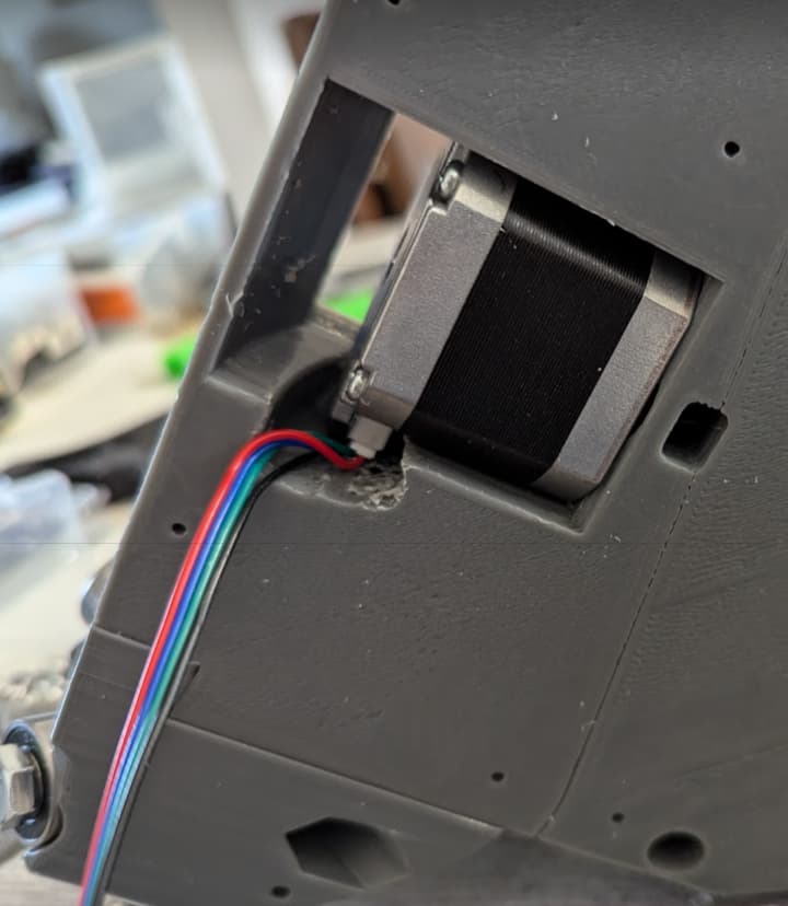
I used a big drill bit and “made” it fit. farmered it, hacked it… whatever. Here’s a photo:
oh and it works just fine. I’d recommend 24 guage wires for the JST-SH connectors on the motor though because getting those crimped connections on the 22 guage wire insulation is somewhat difficult to get right. the JST-XH connectors on the control board are no problem with the bigger wires that are typically used and available.
This is on the beta version - first draft with all the spare parts and extra filament I had to build it. the second one I built - RC3 - had the V1E motors from the shop and not the spares… trying to build to spec.
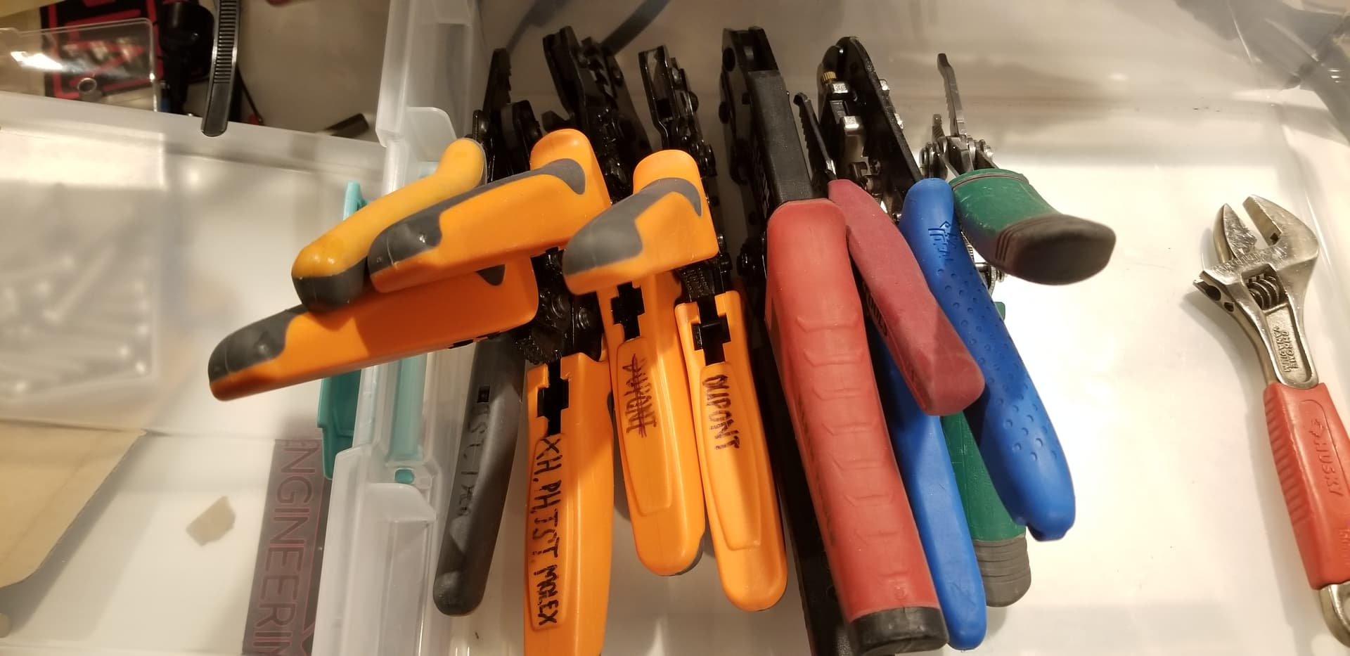
Used to use SN-28b (the striked through crimper in pic below), but would struggle and curse almost every time when trying to get crimped connector to fit in the plastic shell.
Is that a halluicnated purple hoodie Aza and his happy friend the purple unicorn?
I knew you were happier with the alternate crimper- but whoa are you happier.
And it took a few years of you in the process.
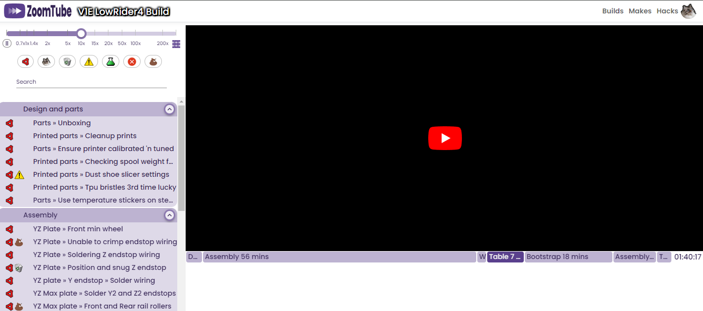
It’s easier than You think. I added a 4 Input I/O Module on the spare port of the jackpot, and modified the Config file to let it work and assigned a function to every input:
-Feed Hold
-Resume
-Macro0 (probe)
-Macro1 (move machine up full Z travel and than to max Y position to clear the working area)
I will! But first I want to finish the V4 Build, take pictures, compile and test the config file, and than share all together in a clear and complete way