"Sandtrails" - a polar sand table

I couldn’t wait. This is just too interesting.

First, I am going to again push for using the theta rho output. Just because it has a lot of the same challenges and I’ve solved them in sandfy. 1) I use a ton of vertices to create lines, so you won’t have to. 2) I am keeping track of movements around the circle, and I am outputting the angle in a continuous angle. So when a line goes from quadrant 4 to 1, the angle is greater than 2pi. 3) It makes the math much simpler.

I’m going to explain the math. Then I will make a quick program to do the conversion (It will be a fun challenge). Then, we can talk about what other challenges remain.

Math

Sorry for the chicken scratches, I am writing this out on paper.

Theta Rho

Theta, Rho is the sisyphus format. It is an angle and a radius.

The radius is always between zero and one. So even though you have 200mm radius, the max rho is 1.0.

Theta is the angle, and it always is continuous. It is in radians, and can be positive or negative. This is a simple pattern that would clear the table with 100 turns:

0,0
200*pi, 1.0

0,0

Let’s make zero on your motors straight ahead. Let’s also make this 0,1 in theta rho. Each of your arms are 0.5r long.

Rho

Let’s always assume your arm can only bend one way. It is really neat that it goes both ways, but it isn’t important which way, and we might as well make it easy on ourselves.

If we want to keep theta at 0, but make r something else, we can do this:

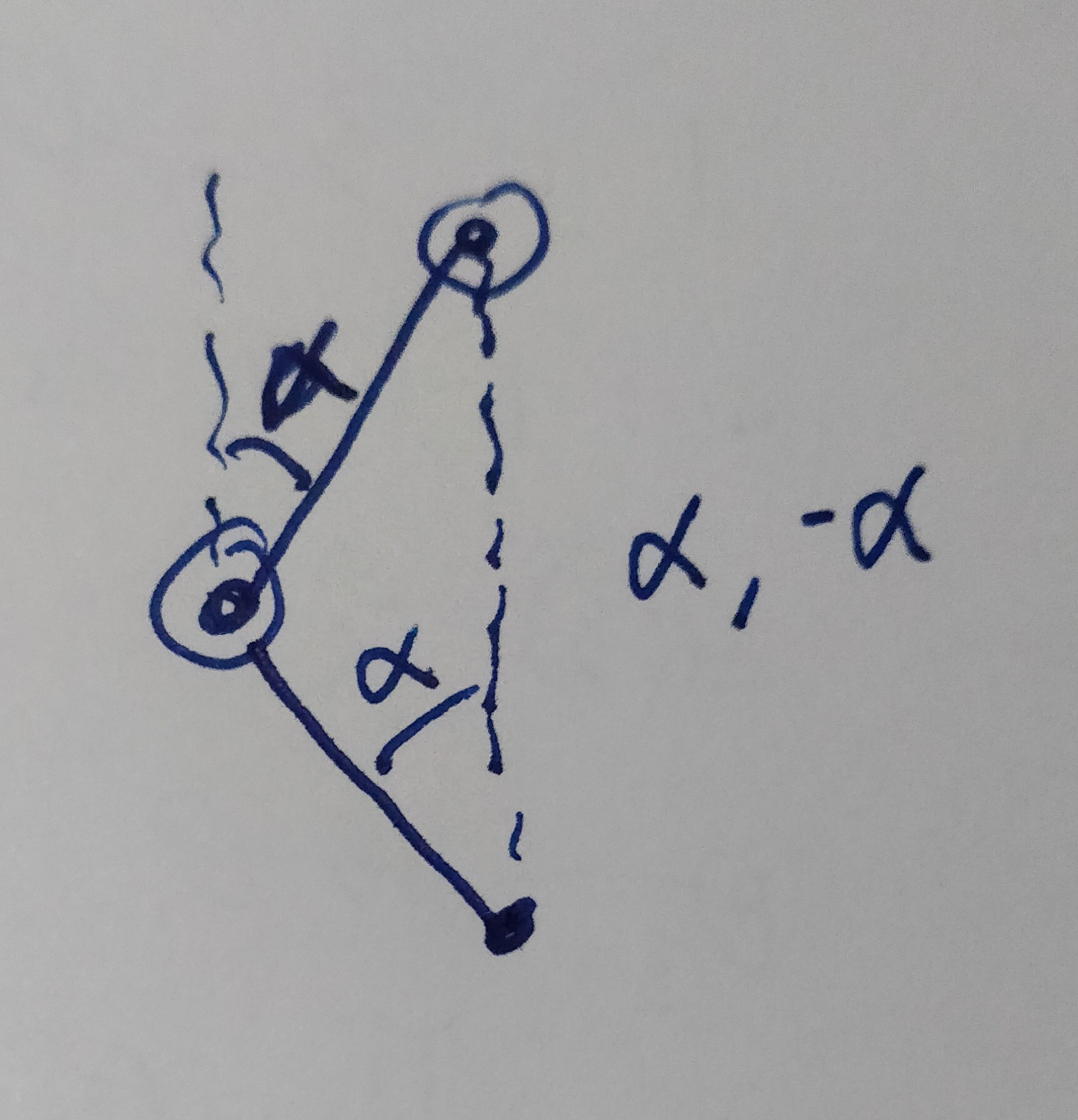
When we do that, the first motor is at alpha and the second is at -alpha. We’ll calculate alpha in a minute.

Theta

So, if we add an angle to both motors, we will move theta, but not Rho.
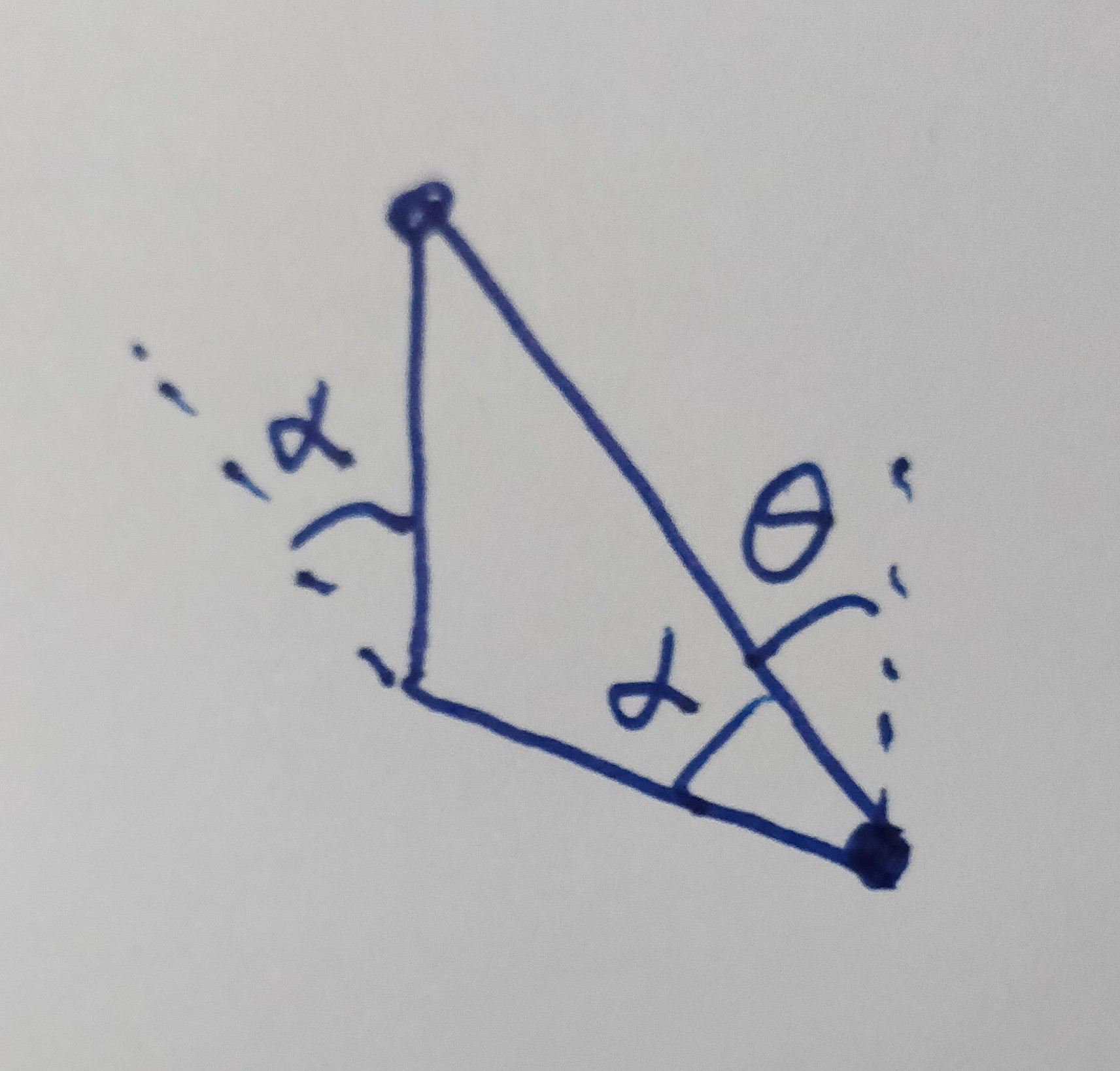
So we have:

Motor1 = theta + alpha
Motor2 = theta - alpha

Alpha

Going back to the triangle when we first saw alpha, we can split it into two right triangles. In the closer triangle, the hypotenuse is 100mm, but we know that is 0.5 in our normalized size. The height is half of Rho, so we have:

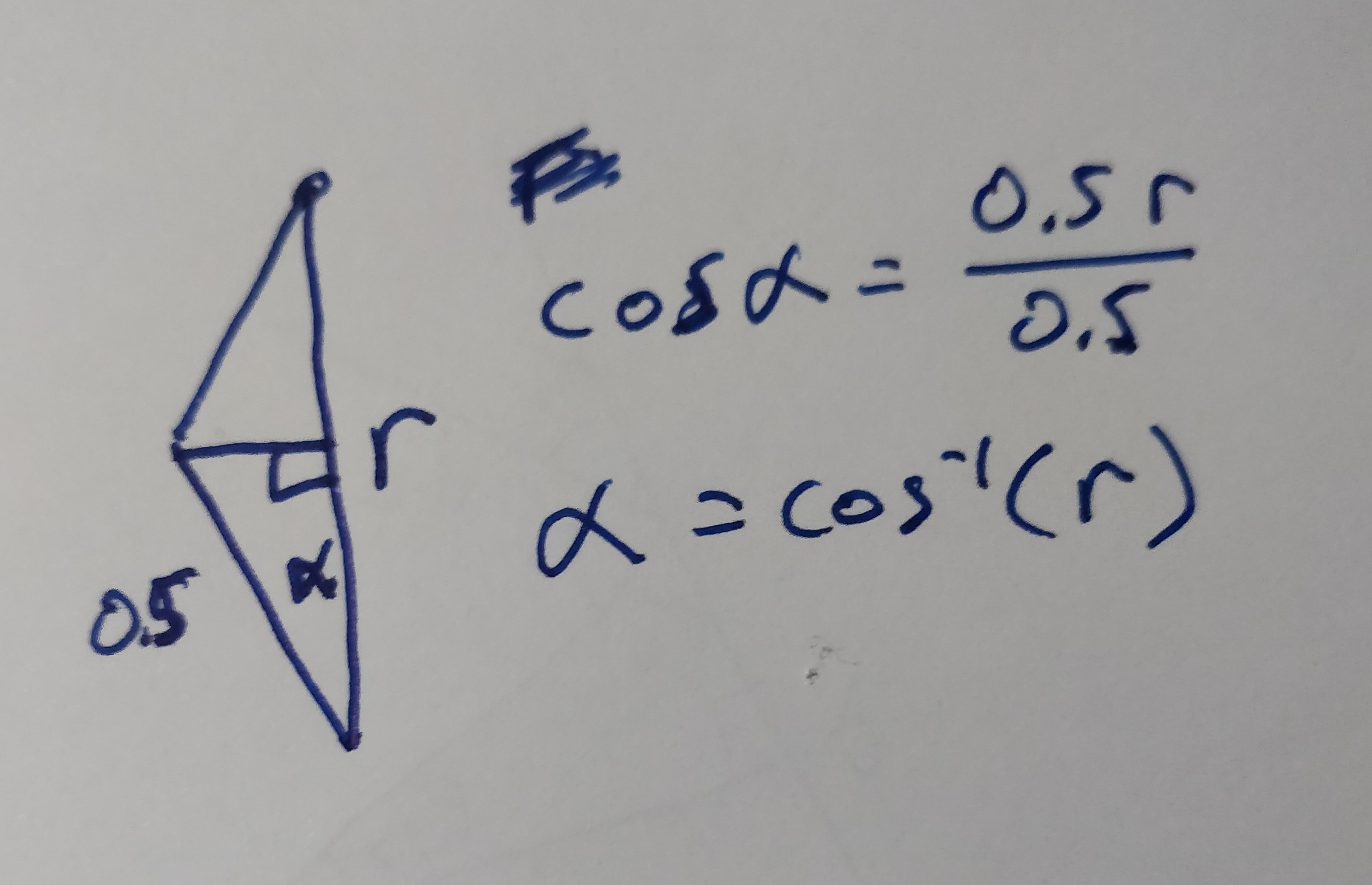
cos(alpha) = 0.5 * r / 0.5 = r
alpha = cos^-1(r)

Motor Output

Motor one (in the middle) I’ll call M1. Motor two (on the arm) is M2:

M1 = theta + cos^-1(rho)
M2 = theta - cos^-1(rho)

Those are in radians. So to get gcode X, Y, we need to multiply by 6.0/(2pi).

Code

Sorry, I don’t know visual basic well, and I run linux, so I don’t think there’s a good way for me to run it. I took a stab at implementing this in python though. I went ahead and used an online editor, so you can go there and try it, without needing python on your machine.

repl.it code

import math

# Config
MOTOR_1_UNITS_PER_ROTATION = 6.0
MOTOR_2_UNITS_PER_ROTATION = 6.0
INPUT_NAME = 'sandify.thr'
OUTPUT_NAME = 'transformed.gcode'

# Open the files.
with open(INPUT_NAME, 'r') as infile:
  with open(OUTPUT_NAME, 'w') as outfile:

    for line in infile:

      # First, separate by content and comments
      parts = line.strip().split('#')

      if len(parts[0].strip()) == 0:
        # This line doesn't have anything that isn't a comment
        outfile.write(line.replace('#',';'))
        continue

      else:
        (theta, rho) = parts[0].split()

        # Here, we're actually doing the math.
        m1 = float(theta) + math.acos(float(rho))
        m2 = float(theta) - math.acos(float(rho))

        x = MOTOR_1_UNITS_PER_ROTATION * m1 / (2*math.pi)
        y = MOTOR_2_UNITS_PER_ROTATION * m2 / (2*math.pi)

        outfile.write("G1 X{:0.03f} Y{:0.03f}\n".format(x, y))          

    # We just moved each motor a bunch. A whole lot.
    # When we start the next file, we don't want it to unroll
    # So we will make the current coordinate something that is small, but the same.
    xmod = x % MOTOR_1_UNITS_PER_ROTATION
    ymod = y % MOTOR_2_UNITS_PER_ROTATION

    outfile.write("G92 X{:0.03f} Y{:0.03f} ; Reset the coordinates\n".format(xmod, ymod))

In that repl website, you can upload a sandify.thr file, and hit run. It will write out the transformed.gcode file, which you can inspect and down.

Running it.

Do you have endstops? You’ll want to make sure the machine starts upright with both arms fully extended, and set to X0 Y0.

At the end, it will have X,Y values out in the hundreds or thousands. When you start the next one, you don’t want to have to reset it, and you don’t want to have to unwind the whole thing. So I added a G92 at the end of the file. You will want to make sure you do things like select the always end on perimeter function in sandfy and then maybe add a G1 X0 Y0 to the end of the file to bring it around to the top again.

If you have resolution problems, you can reduce the steps/mm in Marlin, and increase the config constants in the script. at 6000 segments/revolution, we have a resolution right now of 0.06degrees. That seems about right to me.

This is the pattern I made to test it out:

sandify

transformed.gcode (34.8 KB)

More Thoughts

This was really interesting and I couldn’t stop thinking about it. Thank you for sharing it. I hope all of this is clear, and I obviously didn’t try it on a machine, so I hope got it close to right. I was shooting for clarity, but I can sometimes lean into condescending. This is a tricky problem, I know. I hope I didn’t completely miss the mark.

3 Likes

Wow, you have given me a lot to review here. Thanks much! I don’t have end stops per se, rather I am using two hall effect transistors and magnets to home each axis. On a machine like this I want to be able to locate a repeatable zero location but not have any stops since it can rotate to infinity. I am using bCNC and it very nicely allows me to move the arms from home position to anywhere and call it machine zero and it remembers that location for the next session as 0,0. I will try playing with this and let you know what I can or cannot make sense of.

Wow, the transformed.gcode file worked! VERY cool! At the end the trail went off to the left instead of the right but that is just a setting in the code or in grbl. Since it’s Fathers Day and we are hosting a party today I probably wont have time to look at much more today but this is a great start! Thanks Jeff.
John

2 Likes

:tada: Great!

Happy Fathers Day! I am enjoying some family time this morning myself.

1 Like

Ok, so wow, I just figured out that I can run Python in Visual Studio so I ran your program after pulling down a polar.thr sysiphus file and executing your program. I ran it on my table and it’s perfect! What I thought was probably going to be weeks of work banging my head against a wall, you solved in less than a day! Thanks! You rock!

2 Likes

Awesome. If you don’t mind, please share a video of it cruising with some sandify design. It is a cool machine, you did the hard work, for sure.

Heffe, there’s a .NET implementation for Linux, https://www.mono-project.com/docs/about-mono/languages/visualbasic/ that should compile and run VB on your system.

2 Likes

Oh. I thought mono was for C#. I will check it out. Thanks.

That’s interesting. So the good news is you can run VB on linux. The bad news is you can run VB on linux.

2 Likes

I’m curious, since Marlin is only thinking of the speeds and accelerations of those two angles, how bad the problem of speed variance is going to be. It will be a lot faster on the edge than the middle of the table. I think we could try to force the kinematics into Marlin, and it would be able to keep the ball going at a constant speed, but then the problem becomes the actual motors may need to be going at blazing speeds when the ball is near the middle.

That seems like a lot of work. Mostly because I assume the motion system in Marlin is written to be efficient and not particularly flexible or clear.

But maybe, since we have a ton of vertices in the script, and we know the coordinate frames of the motors and the thr, we can create better speed limits based on the ball speed, and convert them to motor speeds, and then let Marlin manage the max speed and accelerations to keep the motors and arms comfortable.

I would think you could add the feedrate as part of the transformation. Assuming the path is broken into sufficiently small segments (which would be needed anyway for the paths to match the IK model) the desired cartesian speed could be mapped into time elapsed for the segment, which could then be converted into motor feedrates after the incremental rotations are known. And those feedrates could be capped during the transformation or in the firmware. Either way, the speeds should obey the cartesian speeds as long as the motors can keep up, otherwise it’s clamped and it may move slower than requested.

1 Like

Here is a youtube video of the machine running.

2 Likes

That is really cool. I like the little unreachable corners filled with items you’d find on the beach. Thanks for sharing.

1 Like

Beautiful stuff! I agree with Jeff, the seashells are an artistic touch :smiley: :+1:

2 Likes

Goodness @jeffeb3, this is awesome!
I don’t think I have ever witnessed this much helpfulness in any forum in any field ever :smiley:

2 Likes

I was wondering if you ever designed a HAT for the Raspberry Pi. I am looking into a build based upon your design and I was hoping to avoid the full size breadboard.

Hi Wolfspaw,
good to hear you’re looking into this. The breadboard is one of the things I really really wanted to change. It is a first try, huge and ugly.

I had started on one based on the adafruit perma-proto, but not completed to date.
This is what I had in mind:

Hope this helps. Your question also gives me a boost to complete the efforts I’ve started on this board…

Roman…it’s great to hear that the HAT is still “alive”. I am currently working on a G2T timing belt drive for the theta stage. I have some components on order. I 3-D printed a section of the stage outer diameter and looks promising. I will let you know how it turns out.

If you ever want to learn a new skill and have some fun, easyeda is pretty slick and you can then order 10x boards pretty cheap from jlcpcb. They take a little while if you go the cheap option, but they are pretty fun and the extras make good coasters.

Due to inevitable mistakes, don’t order too many until you know they are right.

1 Like

Thanks for the pointer! Looks awesome. I’ll keep this in mind for the future :smiley: