Ok I’m wiring up some LEDs on the LR3. WS2815s. Pulling separate power. I need to put a signal wire from D1 to the SKR Pro 1.2. Best I can find from a google search is to use pin PE4 for this. On the firmware I’m going to enable neopixel. Where it asks what pin do I put PE4? I seem to remember somewhere that the pins can be called something different in Marlin vs the pinout. Just want to make sure I’m doing this correctly. Also while I’m asking is this the best pin to use? If not what pin and what do i call it in the firmware. And also if I wanted to control a second set of lights separate from this one what other pin should i use and what should I call it in the firmware? Thank you for any help at all with this!!! Firmware is my complete weak spot and I’m trying like hell to not let it hold me back. I google and google but I guess I don’t know the right things to search for.
And on a separate note but not at all unrelated note, if one wanted to have an led popping on when a server was working, could one just wire it into the end stop circuit presumably with a gadget to convert voltages correctly. (Asking for a friend.) ![]()
Man that was way more stressful than it needed to be. I guess whatever I was remembering was way off.
I uncommented #define NEOPIXEL_LED
Changed NEOPIXEL_TYPE to NEO_GRB (mine arent GRBW)
set NEOPIXEL_PIN to PE4
Changed NEOPIXEL_PIXELS to 61 (number of LEDs I Installed)
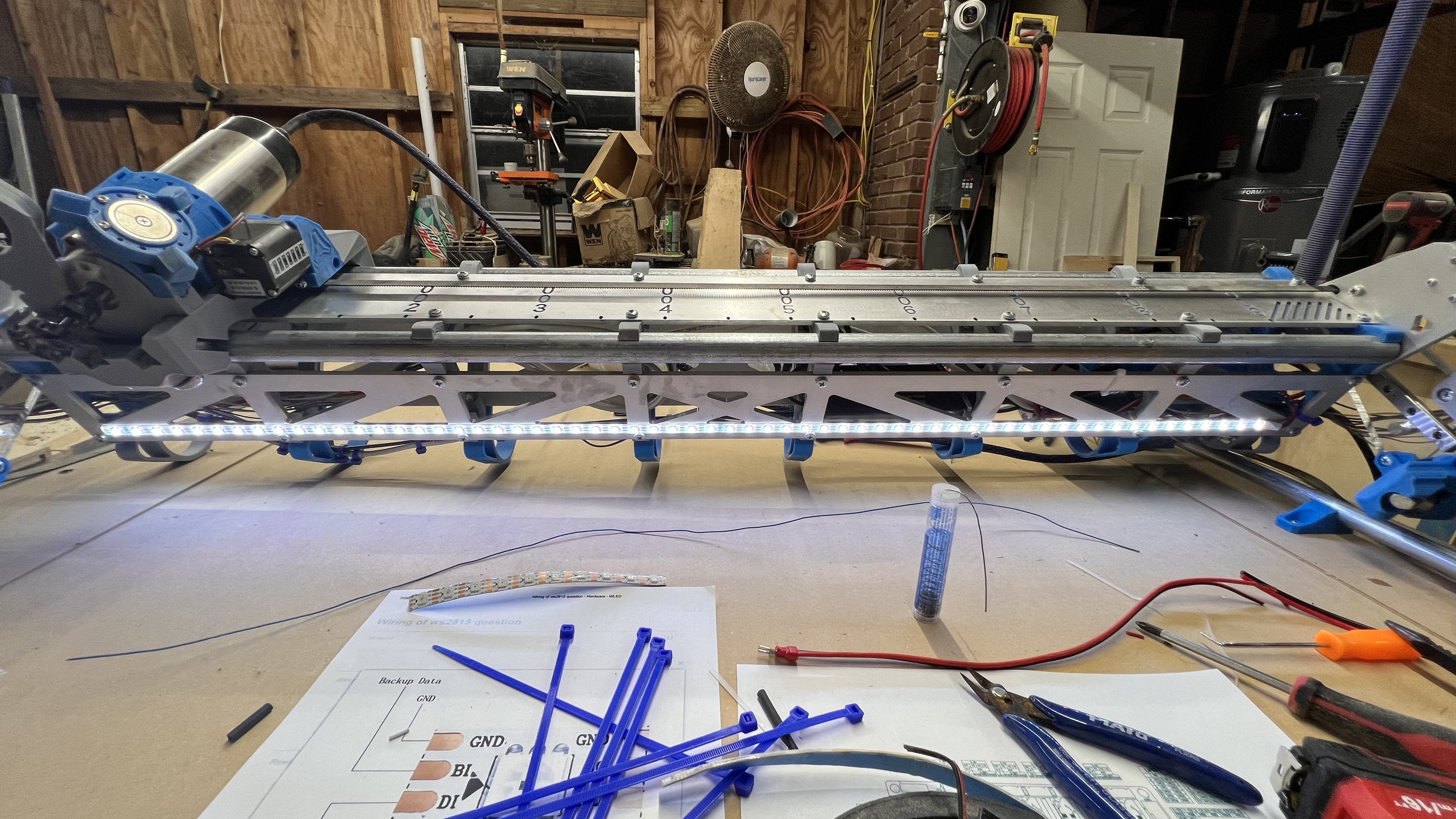
Compiled…Flashed…And LET THERE BE LIGHT!!!
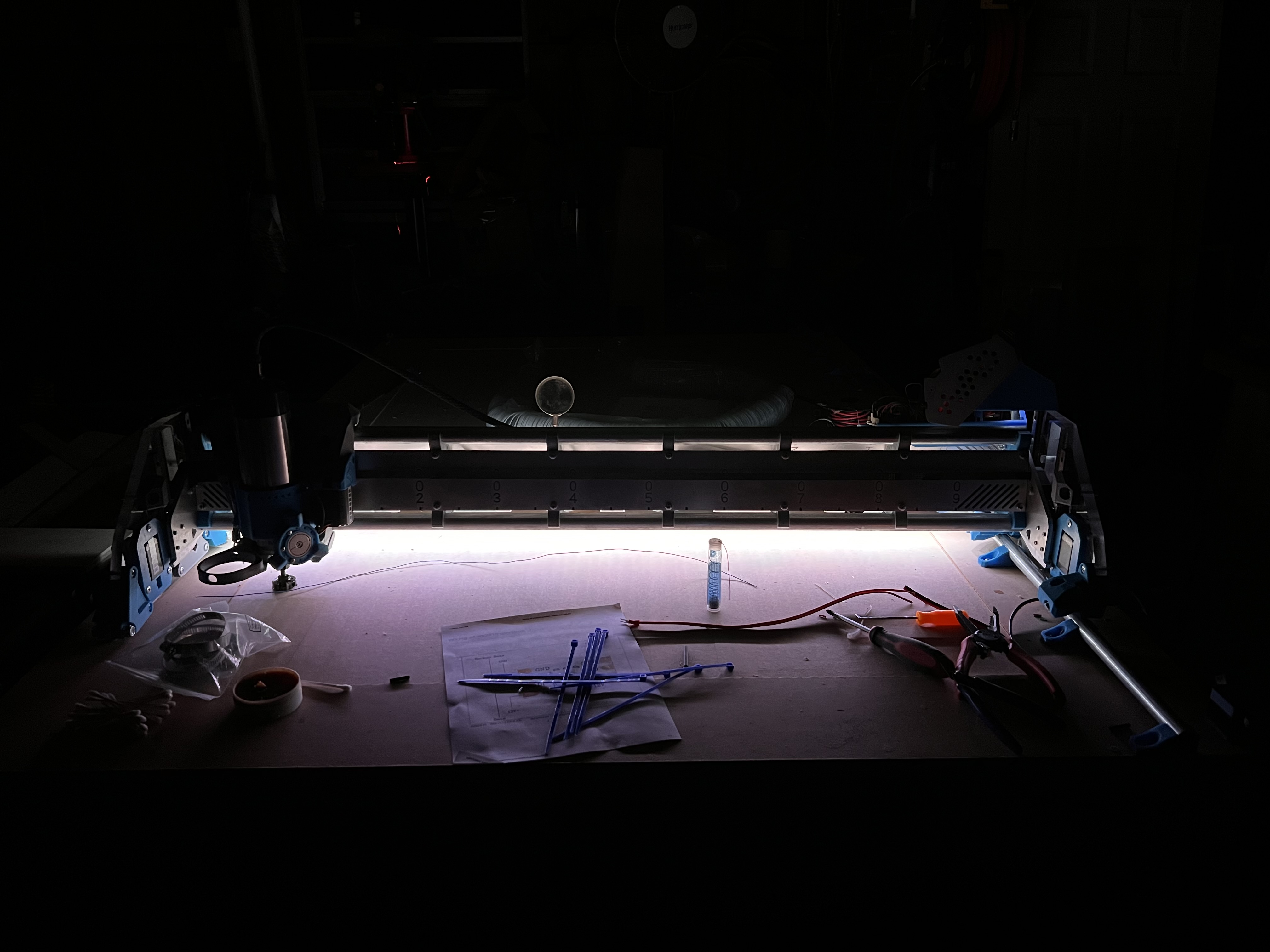
Looks like something out of “close encounters”, how good is that?? ![]()
That’s half brightness on 61 leds. And a completely dark shop. Should light up the work pice nicely.
If your switches are normally open, they will close the circuit when they are pressed. The circuit is between the pullup voltage and ground. Putting a 1kOhm resistor and an led in series in the endstop circuit should limit the current to a few mA.
But if you wanted to invert it, you need a transistor. A transistor circuit has the advantage of also using its own current. Something like the uln2003a would be an easy solution. It can do multiple outputs too.
You should try to program the ones on the outside it that it turns green when it is done, like the MK4 does. Blue when printing (or in your case, cutting), orangee when it needs user interaction (change filament/endmill or sth like that), green when it’s done. And I guess red when something is wrong, but I’ve never seen that.
Yes that would be cool! I know its sorta possible but not sure to the extent. Going to do some more digging around today once my brain wakes up LOL
That’s what coffee and noisy kids were invented for! ![]()
Thankfully my kids are still in bed. Although hard to call them kids anymore, youngest is 14 then 18, 20 year old moved out already. So its quiet here. And no coffee for me. Not sure why but it SPIKES my blood sugar like crazy (I’m type 1 diabetic) so now I drink a monster every morning lol. same if not more caffeine and no blood sugar spike
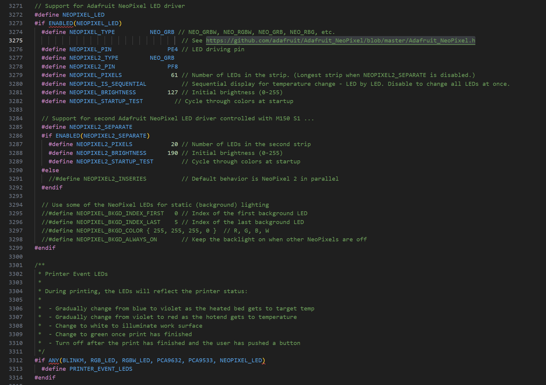
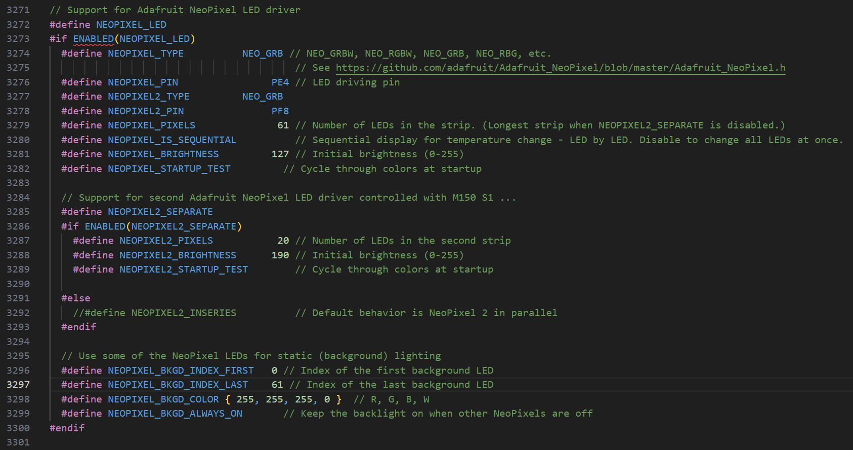
Ok this is what I have the firmware set at currently. I’m now looking harder at this section…
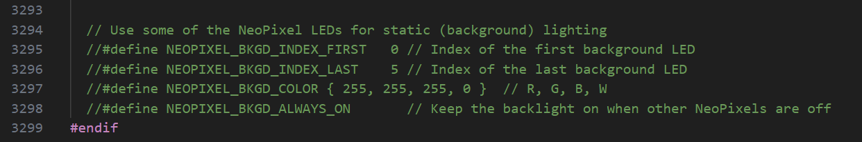
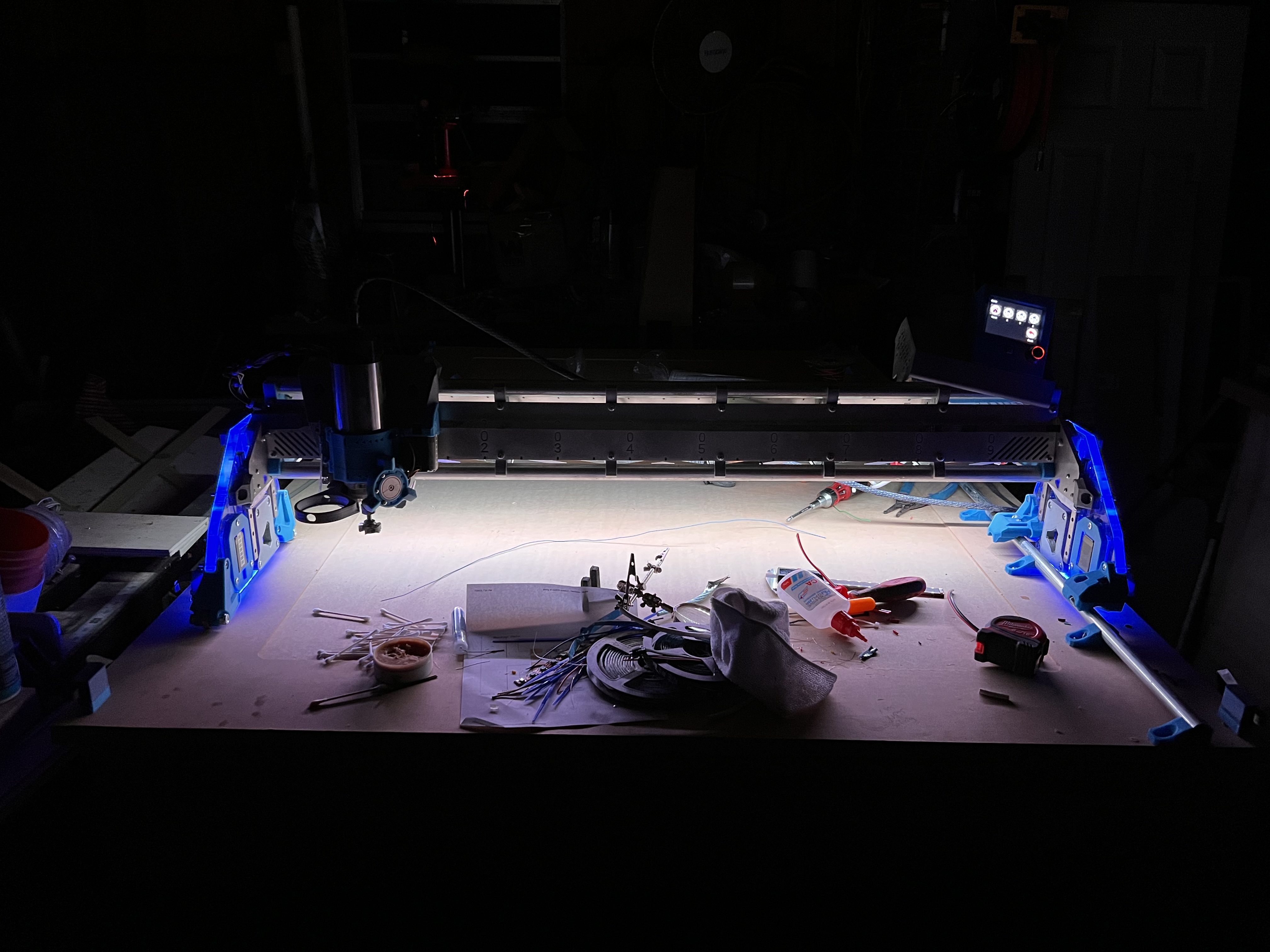
Seems to me that I “should” be able to use this section to set my side panels as “background Lights” and set them to blue, then leave the other lights to be white work lights until the “print” is done and they will turn green.
If I am understanding that correctly then how do I set it for the different strings since i am using NEOPIXEL2_SEPARATE? I get the index part but can i put which String??? the documentation I can find on this is not written in dumbass so I can understand it LOL
No idea if this is going to work yet but im going to give it a go…
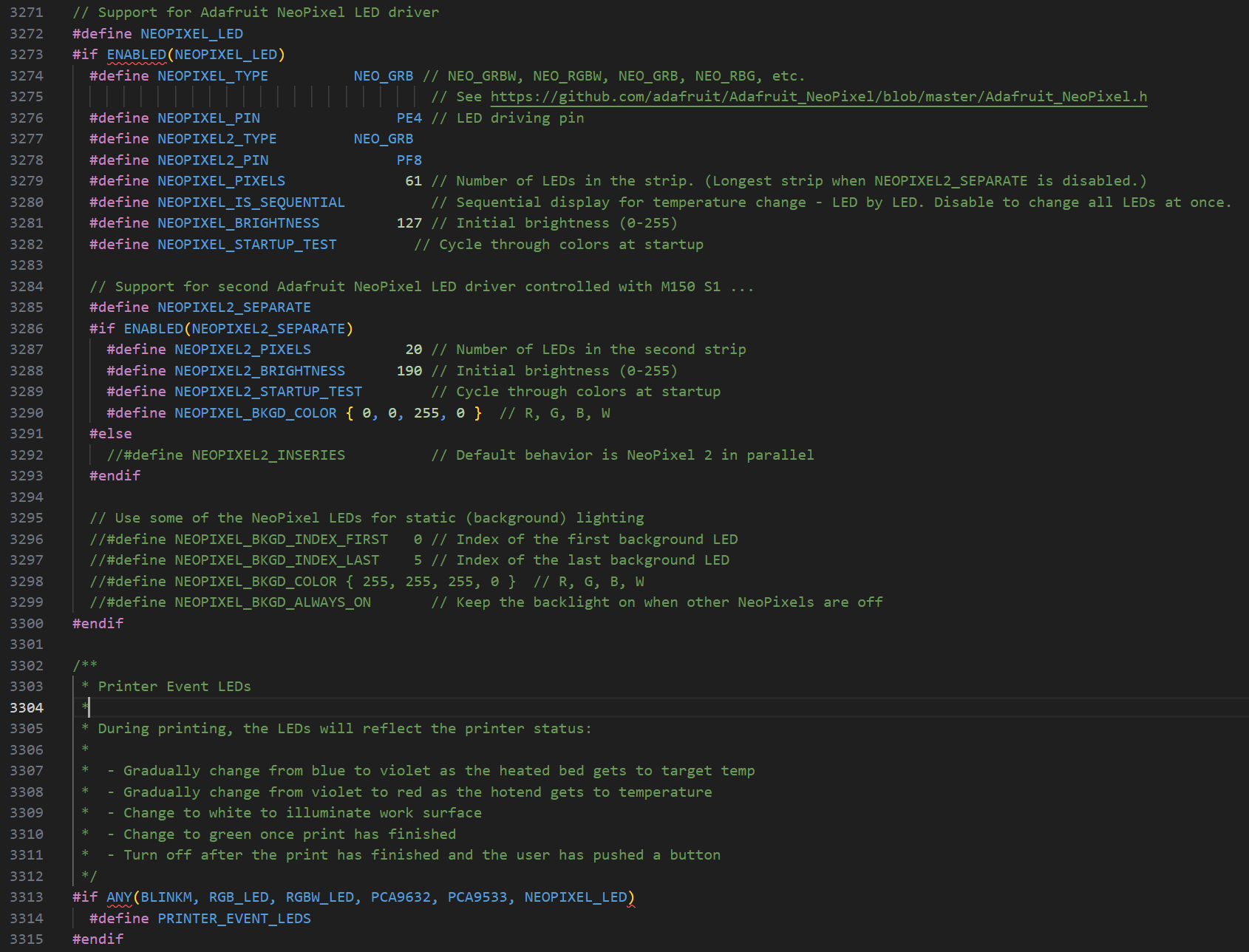
I copied this line and added it under the NEOPIEXL2_SEPARATE
Building now so we will see LOL
Edit: Nope…didn’t work
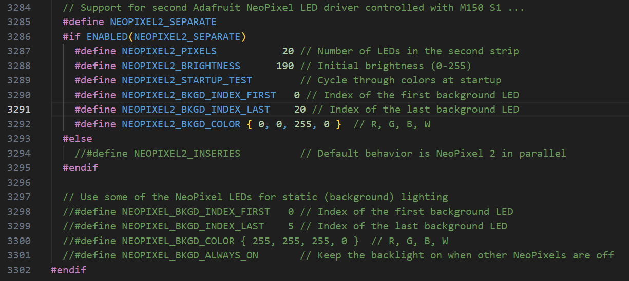
ok tried this… and no it didn’t work lol
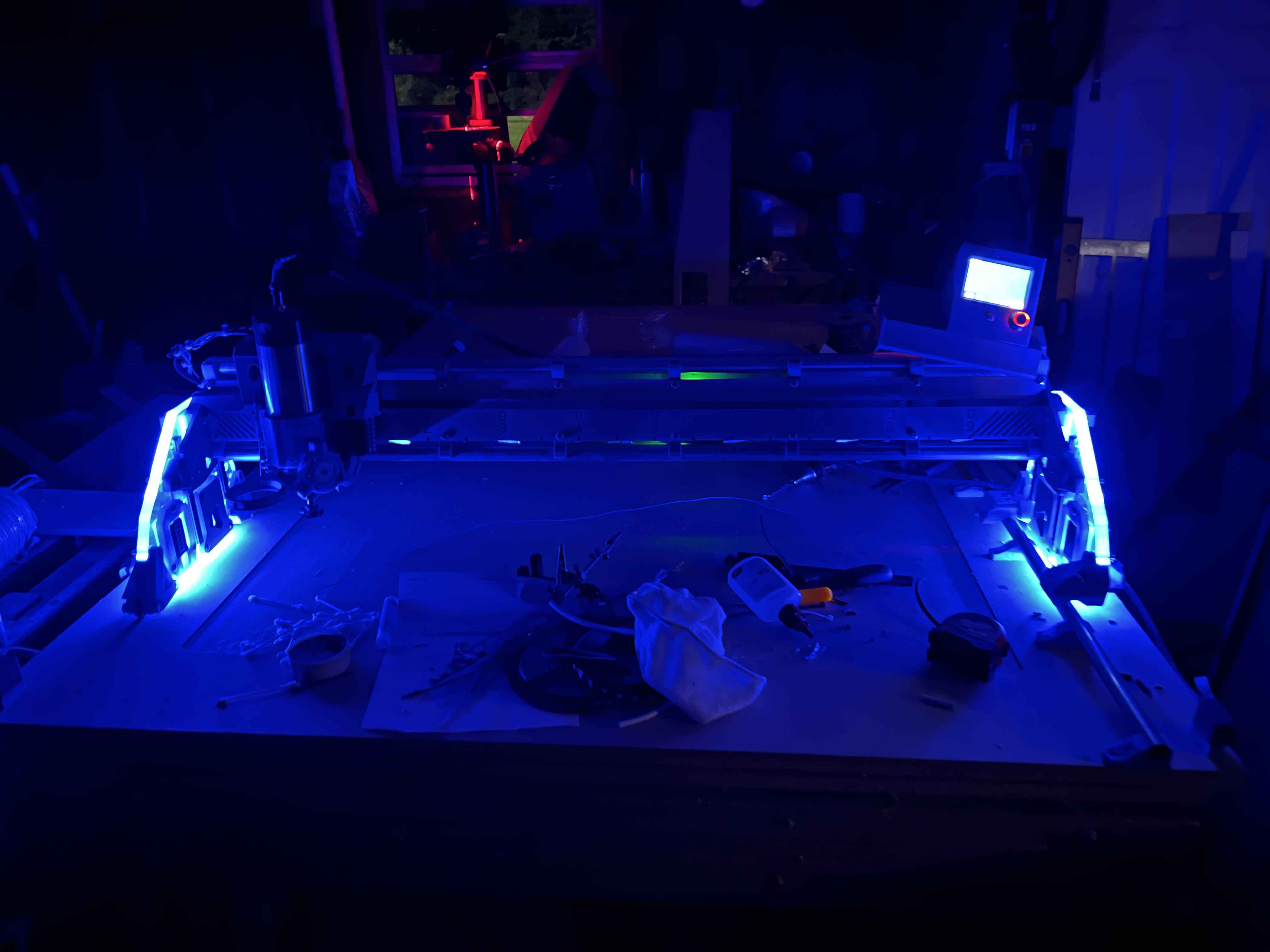
But i decided to go ahead and let it do an air crown to see what happened. Side lights never came on other than the first test at startup. Beam lights stayed on until the crown was done then they turned red. once i hit ok on the screen for print done they turned off. Trying to figure out how to get the side panels to turn on at startup, although i may just have to put a M150 S1 B190 in my startup gcode for them. And I guess I could put a M150 S0 W127 at the end gcode to turn those back white. Idk. I’m so beyond my knowledge base here but still trying LOL
This is great progress! ![]() If you can get it working I’d love to have it as well because it’s just too cool.
If you can get it working I’d love to have it as well because it’s just too cool. ![]()
Just ran another test with this…
Blue side panels did not come on. White beam did come on, and stayed on after the “print”. I can turn the side panels on with M150 S1 B190. Is there a way to set it in firmware to automatically run this at startup? Or do I just need to make a gcode file on my SD card and hit it each time I start?
Also thinking about trying to turn the back light section off again and then run M150 S0 W127 in the ending gcode, probably with a M0 in front of it. Then I should get the color change at the end of a job then hit one button on the screen and go back to white. Can also probably put something in the tool change G code to change the color for that as well… so many possibilities just have to try them out LOL
Figured out why it went red instead of green at the end of the job. Had it set as GRB which is what i have always needed to use for these strips. Went out to the terminal and ran M150 S1 R150 and they came on green. Ran M150 S1 U150 and they came on Red. So I’m changing it to RGB in the firmware and going to try it again. Also went ahead and commented out all the static lighting and going to try control in gcode and see how that goes.
Now It doesn’t switch to green at the end on its own. And I believe that’s because I set the M150 to switch it back to white after the code. And I still cant figure out how to get it to turn on the side plates at start up so I came up with a work around for all of these…
Start gcode…
M150 S1 B190 ; Turn on Side Plate LEDs Blue
G92 X0 Y0 ; Set Current position to 0 on the X and Y axes.
M150 S0 R127 B127 ; Set Beam LEDs Purple
M0 Attach probe ; Pause to connect touchplate
G38.2 Z0 ; Probe down to touchplate
G92 Z0.5 ; Set new Z position to thickness of touchplate
G1 Z2 F900 ; Lift off touchplate
M0 Remove probe ; Pause and wait for touchplate removal
M150 S0 R170 U170 B170 ; Set Beam LEDs White
Tool Change gcode…
M150 S0 R127 B127 ; Set Beam LEDs Purple
G28 Z ; Raise Z
G0 X0 Y0 F2520 ; Drive to tool change side
M00 change tool, probe ; Pause to change tool and attach probe.
G38.2 Z0 ; Probe to touchplate
G92 Z0.5 ; Set Z to touchplate thickness
G00 Z5.0000 F500 ; Lift off touchplate
M00 remove probe ; Pause to remove touchplate
M150 S0 R170 U170 B170 ; Set Beam LEDs White
End gcode…
M150 S0 U170 ; Set Beam LEDs Green
M05
G28 Z
M0 ; Wait for Manual Spindle Shutdown
M150 S0 R127 U127 B127 ; Set Beam LEDs White
M30
Start and end have tested good. Will test the tool change later but I see no reason it wont work.
