Make something before your wife wants it gone!
4 Likes
OK we need to let Ryan weigh in on what to do about your board, but you do have a functioning machine and can explore more.
Without limit switches you’ll need to manually zero and manually square, but you can proceed with exploring your machine.
If it were me, I’d celebrate with a cold beverage.
I said that, my apologies I don’t daily drive Windows and it used to be true, but may no longer be true.
2 Likes
Sounds like a plan. I’m not in a super hurry, but I don’t really want to build this thing more than once, and I’d like to do a good job on it. Once we decide what to do about the board, I’ll move forward with the other stuff. Until then, it can sit.
Speaking of endstops, I assume there’s info somewhere about how they’re supposed to be installed, and files for the mounts and such? I can be working on all that…
There’s some docs here, which you might have already found:
I’ve never built the MPCNC, only the LR3/4.
I Think the latest enstop parts are here (I’d like Ryan or an MPCNC owner to confirm)
The dual endstops were once considered unnecessary until the auto-squaring coupled with homing became well tested.
Ok, made a little progress….
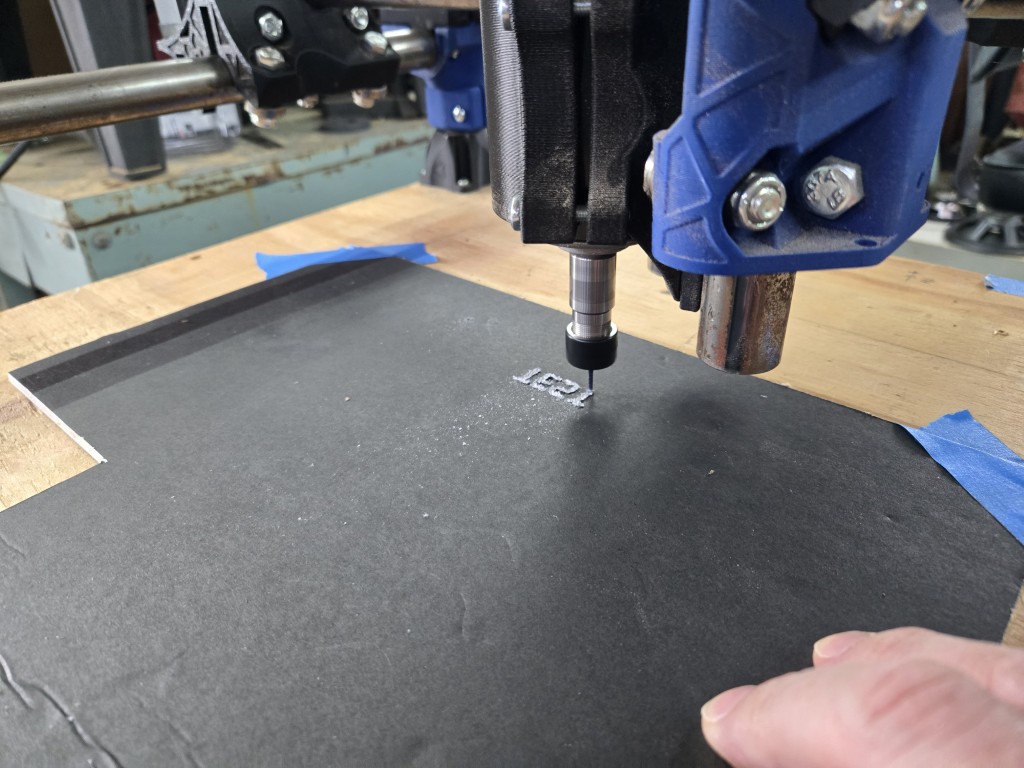
I decided to temporarily wire it up, so I can mess with EstlCAM a bit, and see if this spindle is worth anything or not.
Long story short, I got it to run, and cut the test crown!
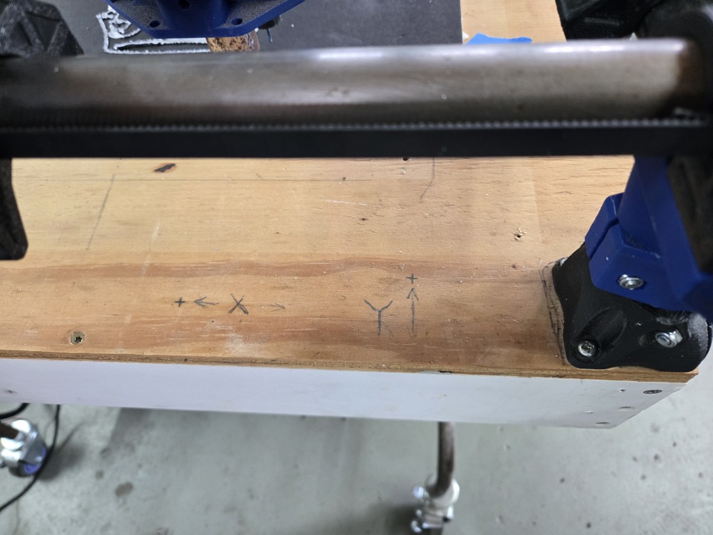
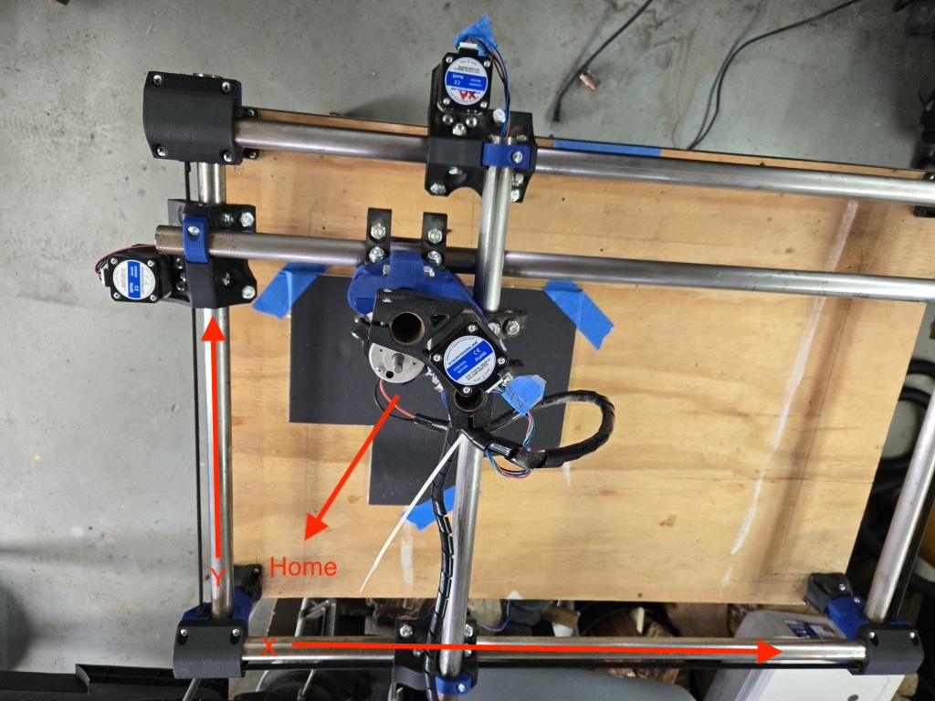
However, the whole machine is mirrored, by which I mean that X0, Y0 (machine origin) is not the lower left corner of the machine, it’s the lower right, for some reason. It looks like the previous owner built it that way, because the bed is labeled (see photos). How would I go about fixing the axes so they are correct? I know I’ll lose a little bit of working area, since the carriage is actually set up for the current orientation, but I’ll take that over all my cuts (and especially text!) being reversed. ![]()
EDIT: Now that I look at the photo… I’m not sure it is set up for lower right origin. I think it’s just wired weird, right?

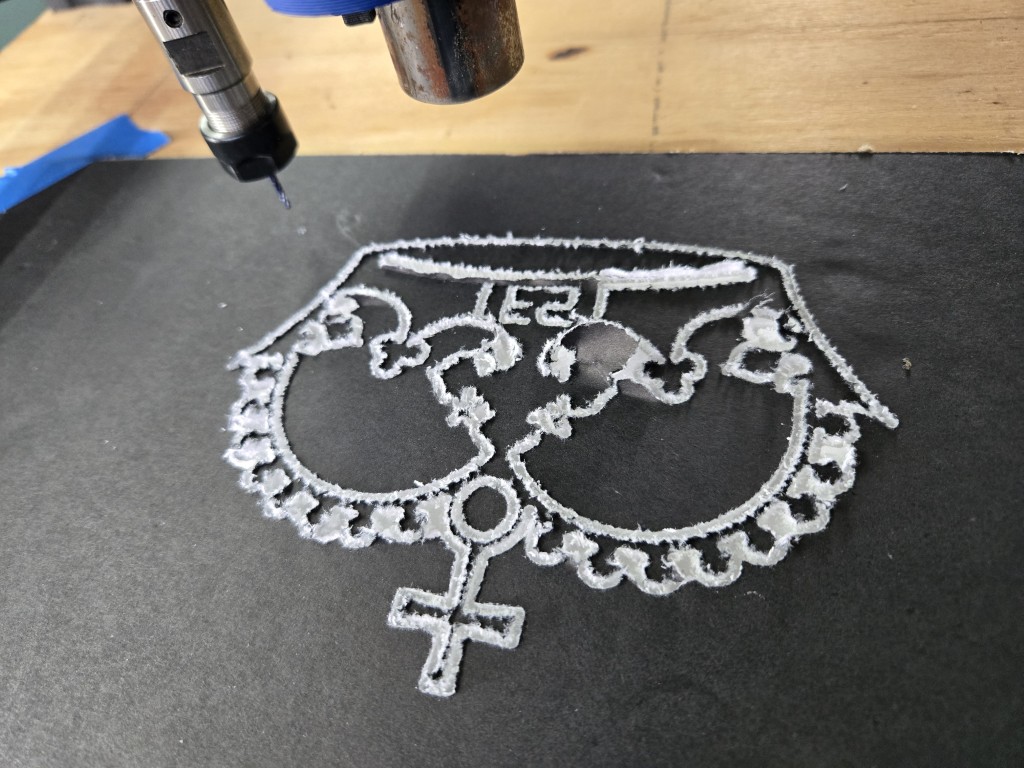
The cuts are all fuzzy because I was using cheap foamcore. It’s all I had handy.
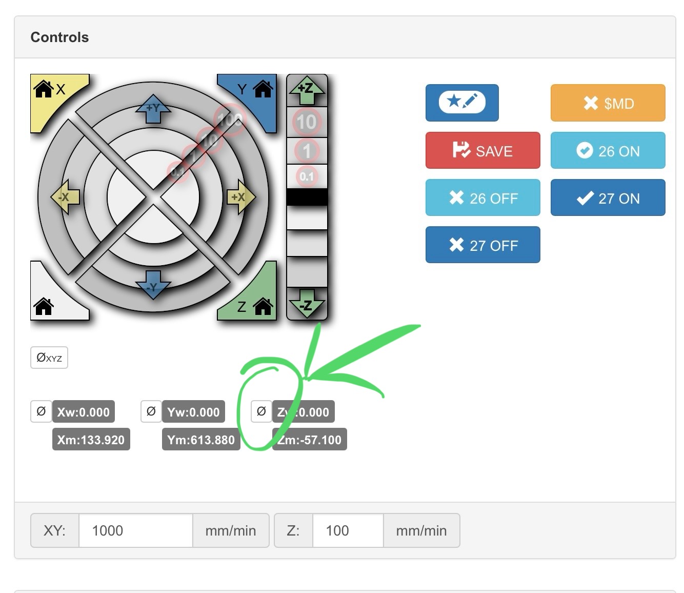
Also… How on earth do I set the home positions in the web GUI? I accidentally touched the home button, and it crashed the machine into the X-axis limit until I could power it off.
There’s also no STOP button on the GUI. Should there be? I mean, there should be, but is there one that I’m not seeing?
A wise man once said “the more I learn, the more I realize how little I know” (or similar) ![]()
1 Like
Ok, I see that now. Thanks guys.
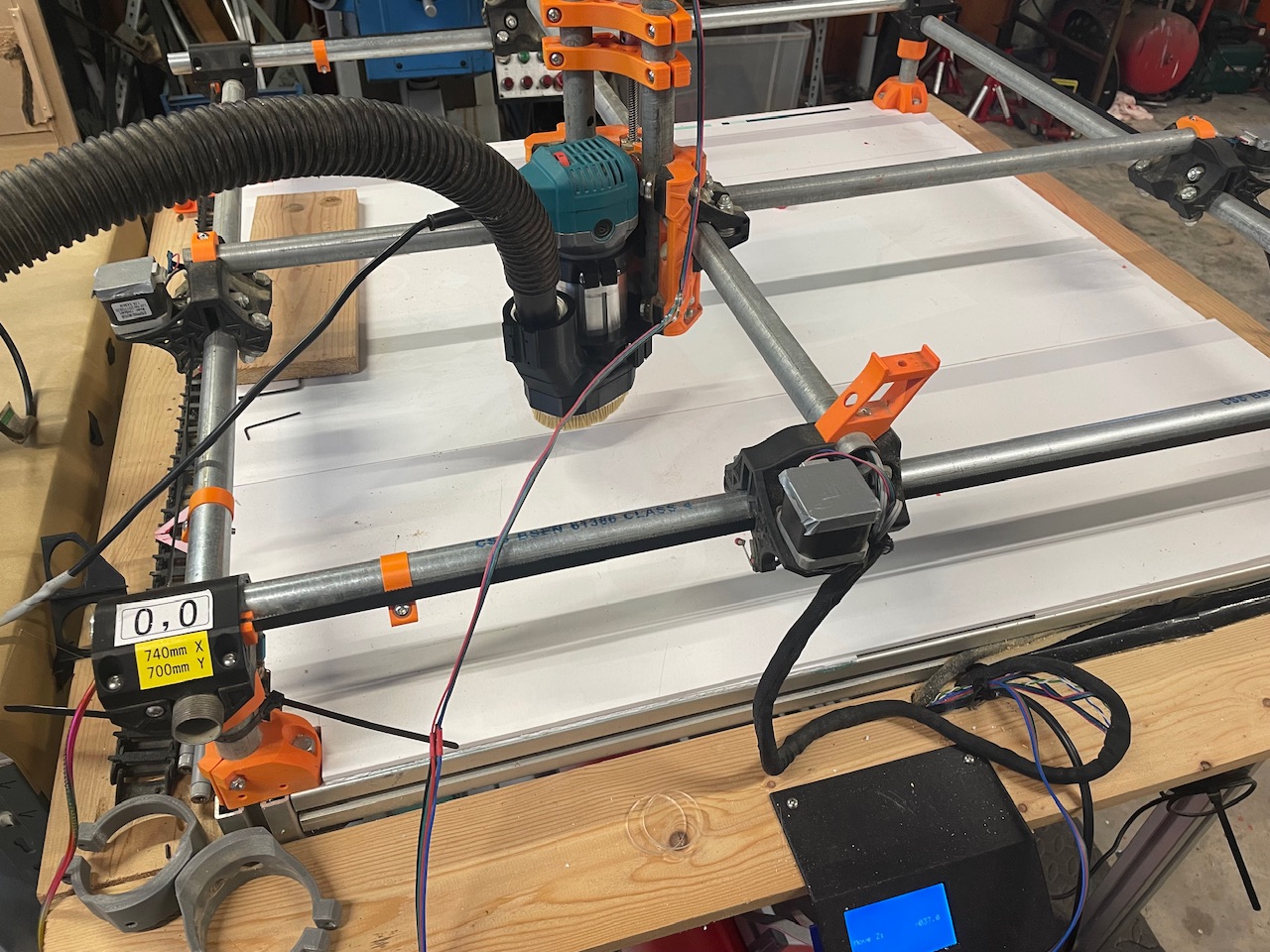
Very clean machine, @Dreyfus ! I like the size, also.
EDIT: Ignore all that (if you happened to see it), I got the axes fixed. It was a simple matter of just swapping the cables from each motor to the opposite channel on the Jackpot.
Now the machine origin is where it should be! Rejoice!
One thing that’s still odd… the Z-axis: + motion is away from the bed (upwards), right?
That seems most intuitive, but watching the machine move during a job, and looking at the gcode, I’m just not sure…
For example, I made a simple test job in estlCAM with some sample text. I wanted to be sure it was cutting the right direction. At the beginning of the gcode, I see this…
G21
G90
G94
G92 X0 Y0
G00 X0.0000 Y0.0000 Z0.0000 F2400
G00 Z5.0000 F900
What’s that Z5.00 for? I would expect it to be moving the bit towards the bed, in order to begin cutting, but it actually is moving away.
I figured, ok, maybe I just have it backwards, so I flipped the channel, so that + motion was towards the bed. That just resulted in the machine mostly cutting air, and only plunging into the workpiece during moves. What am I missing here?
1 Like
So I dug around in EstlCAM and the cgode a bit more, and I think I’m starting to piece a few things together (he’s learning!), but I haven’t yet discovered what’s causing the odd behavior…
Here’s the (clipped) code:
[please tell me if I’m interpreting these codes correctly]
(Project Text Test Cuts)
(Created with Estlcam 12.141)
(Machining time about 00:03:05 hours)
(Required tools:)
(Pen)
G21
G90
G94
G92 X0 Y0
G00 X0.0000 Y0.0000 Z0.0000 F2400
G00 Z5.0000 F900 ← this is a clearance plane movement, right?
(No. 1 Hole machining: Hole 47) ← Job starts
G00 X10.8206 Y5.3935 Z5.0000 F2400 ← another clearance plane movement? The bit is now way too high to contact the material
G00 Z0.5000 F900 ← spindle moves up another 0.5mm (why?)
G01 Z0.0000 F300 S24000 ←setting rpm? (mine is manual)
G01 Z-1.0000 F300 ←spindle moves down 1.0mm (this is the correct depth of cut)
G01 X13.0311 F900
G01 Y15.3452 F900
G02 X13.0811 Y15.3952 I0.0500 J0.0000 F900
G01 X15.9973 F900
G01 Y17.2935 F900
G01 X7.8854 F900
G01 X7.8755 Y15.3952 F900
G01 X10.7706 F900
G02 X10.8206 Y15.3452 I0.0000 J-0.0500 F900
G01 Y5.3935 F900
G00 Z5.0000 F900 ←Spindle moves up for clearance, in prep for move to next position, yes?
(No. 2 Hole machining: Hole 48)
G00 X10.8206 Y5.3935 Z1.0000 F900 ←spindle moves up 1.0mm, why?
G00 X17.8973 Y5.3935 Z1.0000 F2400 ←spindle moves up 1.0mm, why?
G00 Z0.5000 F900 ←spindle moves up 0.5mm, why?
G01 Z0.0000 F300
G01 Z-1.0000 F300 ←spindle moves down 1.0mm, but at this point is way up off the material, just cutting air…
G01 X24.5102 F900
G01 Y7.2293 F900
G01 X20.1577 F900
etc…
[skip to the end]
G03 X115.8218 Y31.4411 I-0.0314 J0.9892 F900
G03 X116.3966 Y33.5022 I-1.9925 J1.6663 F900
G03 X115.9635 Y33.8981 I-0.5845 J-0.2045 F900
G00 Z5.0000 F900 ←Spindle moves up for clearance, end of job
G00 X0.0000 Y0.0000 F2400
G00 Z0.0000 F900
M63 P1 (stop spindle pin27)
G91
G0 Z15
G90
M30
So, what am I seeing here? It’s not cutting properly, but I can’t tell if it’s because I did something wrong in EstlCAM, or if there’s something off with the machine.
When I run the preview sim, everything looks correct as far as I can tell.
This is just a Z movement up to your clearance plane height. No X Y movement
This is a rapid movement to the start position for the first hole. Z is at the same height as the end of your start gcode
This is Z moving down from 5mm to 0.5mm from where you set 0 at
This is moving Z from 0.5mm to 0. Estlcam is telling it the speed you have set for the bit, since yours is manual (like 99% of us) this is ignored by the machine.
Correct.
Yes
None of these are moving up. You seem to be thinking of these numbers as relative but they are not. For the life of me I can not think of the right word right now. ![]()
Hopefully this helps a little bit. I see you aren’t using a probe to set Z0 so are you making sure that the bit is touching the top of the work piece when you start the job? I am sorry if you answered this already earlier in the thread and I missed it.
2 Likes
Absolute. ![]()
Edit- wait till you try and wrap your head around all the supported work coordinate systems. We’re literally only scratching the surface here.
3 Likes
Ok, that helps a lot, thanks!
I totally forgot about that very first G94, setting the machine to absolute coordinates. ![]()
I’m used to working with my 3D printer, which works relative, and it was messing me up.
However, that still doesn’t totally explain why it’s cutting air.
Yes, I’m starting the job with the bit just not quite touching the work surface.
I have the probe/touch plate system (bought the whole kit from Ryan), but I don’t want to set it all up until I get the board issues sorted out, and everything wired up in the final config.
The same applies to the endstops. I really want to do all the complicated stuff once.
Anyway, with the bit not quite touching, and the spindle running, when I press GO! on the job, the first movement is 5mm up (as expected), but then it just never comes down enough to contact the material, let alone cut.
Now that I understand a little better what I’m expecting to see, I’ll try again, maybe with an even simpler job, and see if I can figure out where things go wonky. I may even try to rig up the touch plate temporarily, to see if that makes a difference in how it behaves.
Thanks for the explanations!
Air cutting is a sensible test of your gcode.
You tell the machine that z=0 (which ought to be the to-surface of your material) is 20mm up the the air and run the gcode to check it.
Yeah, that’s fine, if I was trying to do that, which I was not. ![]()
As far as I know, I had everything set up for a real cutting job, but it just jumps up and starts cutting air. I wonder if this machine knows I’m not ready… ![]()
You’ve told the machines it’s at x0 and y0 but not z0, it could be that unless you already moved the tooltip to the surface and sent a G92 z0 command.
1 Like
I thought that was odd also, but I didn’t generate the gcode. ![]()
This is the output from EstlCAM, using the suggested setup from the V1E docs.
Hang on…. I took out the part about the touch probe, since it was crashing the spindle into the table with no probe attached. I wonder if that’s why it’s not looking for a z0?
But that homing line was generated by EstlCAM, after I removed the starting code about the probe…so I’m still confused. lol
Yes. If you modify the gcode to
G92 X0 Y0 Z0
and then move the top of the tool to the surface of your material in the lower left of the workspace it should work.
estlcam has settings for starting and ending gcode which is added to each file, you can put the modified code there.
1 Like
Yeah, I followed the guide, which included that section.
Are you saying I need to include that “G92 X0 Y0 Z0” as part of my startup code, at least until I begin using the probe? That makes sense, I’m just trying to be sure I understand correctly.
Good catch! I totally missed that!