I posted this in the MPCNC Reddit sub, but they suggested I’d get more knowledgeable help here…
So I just bought my first CNC…kinda. lol
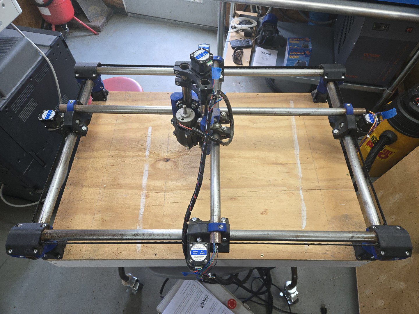
It’s an MPCNC that someone got mostly built and gave up on due to…issues.
I have a laser and 3D printer, and I work in CAD for my job, so I know the basic concepts, but I know just about zero when it comes to CNC machines, so I’ll need some help troubleshooting this machine.
The (main) problems are twofold:
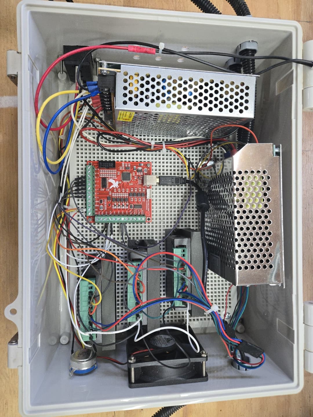
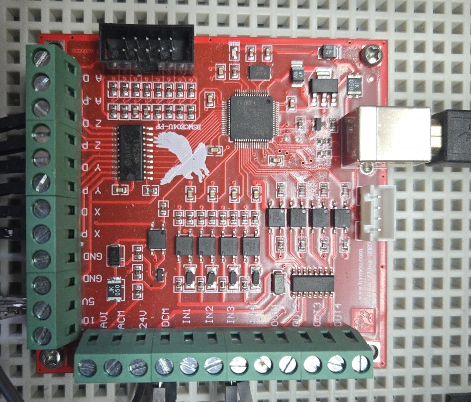
It has a Mach3 control board, which seems to be nonstandard for these machines, based on what I can see on the MPCNC web site. I know nada about Mach3. It that a good choice for running this machine, or do I need to be considering a move to a different control system? I also have a RAMBo v1.4 board for it, if that’s any better.
Before I bought it, the seller demonstrated the problem. It seems that the steppers in the Y-axis aren’t moving in sync. When a Y-travel move is called, it kinda wobbles, for lack of a better term, like it’s taking turns moving each stepper in succession, rather than together. I now believe this to be a mechanical issue in the Y-Axis. Even with no power, I can move the gantry, and it sort of shutters or chatters. It’s not always at the same spot on the rails. This video illustrates the problem: https://youtu.be/gBdsCFuXIdQ
When you look at the photos, your first thought will probably be rust on the rails. I promise, they are not nearly as bad as they look. I’ve rubbed them down with 0000 steel wool, then wiped down with CorrosionX. If you don’t know this stuff, it’s an aerospace anti-corrosion fluid. Good stuff.
The rails are smooth. The key thing in my mind is that the stutter doesn’t happen at the same point each time, as I move it back and forth.
Any ideas?
I hope to use this machine as a learning tool to get me into the CNC world, so I can make a more informed choice when I’m ready to move up to a larger machine.
That can work but I don’t think anyone around here has used that in 20+ years. You would be on your own.
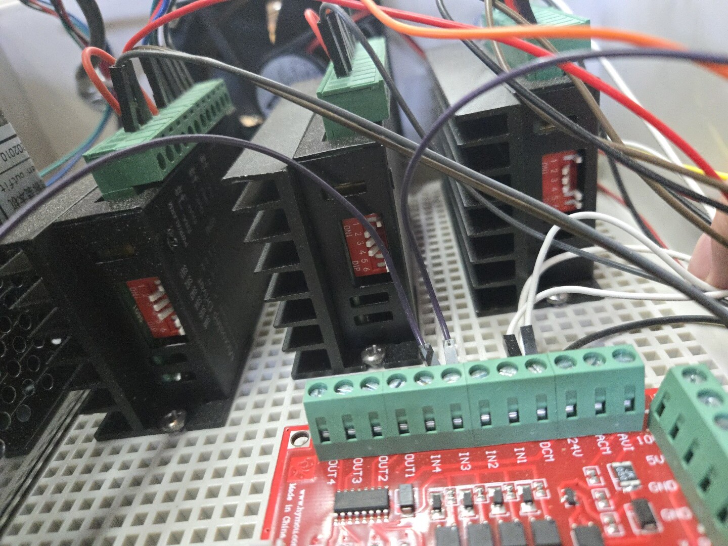
That must be a config problem with the control board you are using. Also those external stepper drivers are not well suited for our steppers, the control is extremely coarse, that has 500ma steps, which is about 10x the 50ma we typically adjust in.
The rambo is something we are all familiar with (from a handful of years back), although these days the jackpot is simple in comparison. The rambo get flashed pretty easy with our preconfigured files in the docs and the wiring pictures are all still there.
I have an MPCNC that I bought all the hardware for from Ryan. It originally had a miniRambo controller. I have upgraded to the Jackpot with endstops. I highly recommend this upgrade for you. It has made using the MPCNC much easier.
I can’t tell if your stepper motors wires have the correct connectors for the Jackpot. The Rambo connectors are the same, so if they will plug into it, they will work with the Jackpot.
Thanks guys, and I will very likely update/upgrade the control system, once I get the machine in a basically functional state.
At the moment, I’m focused on sorting out this mechanical issue with the frame.
I’ve determined that the frame/rails are not square.
I removed the main structure from the legs, and used the documentation on the site (Great job Ryan!) to make sure the base is correct as a first check. The legs are perfectly level, but here’s where it gets weird…
Can some of you mathy types look at this and tell me how this is possible?
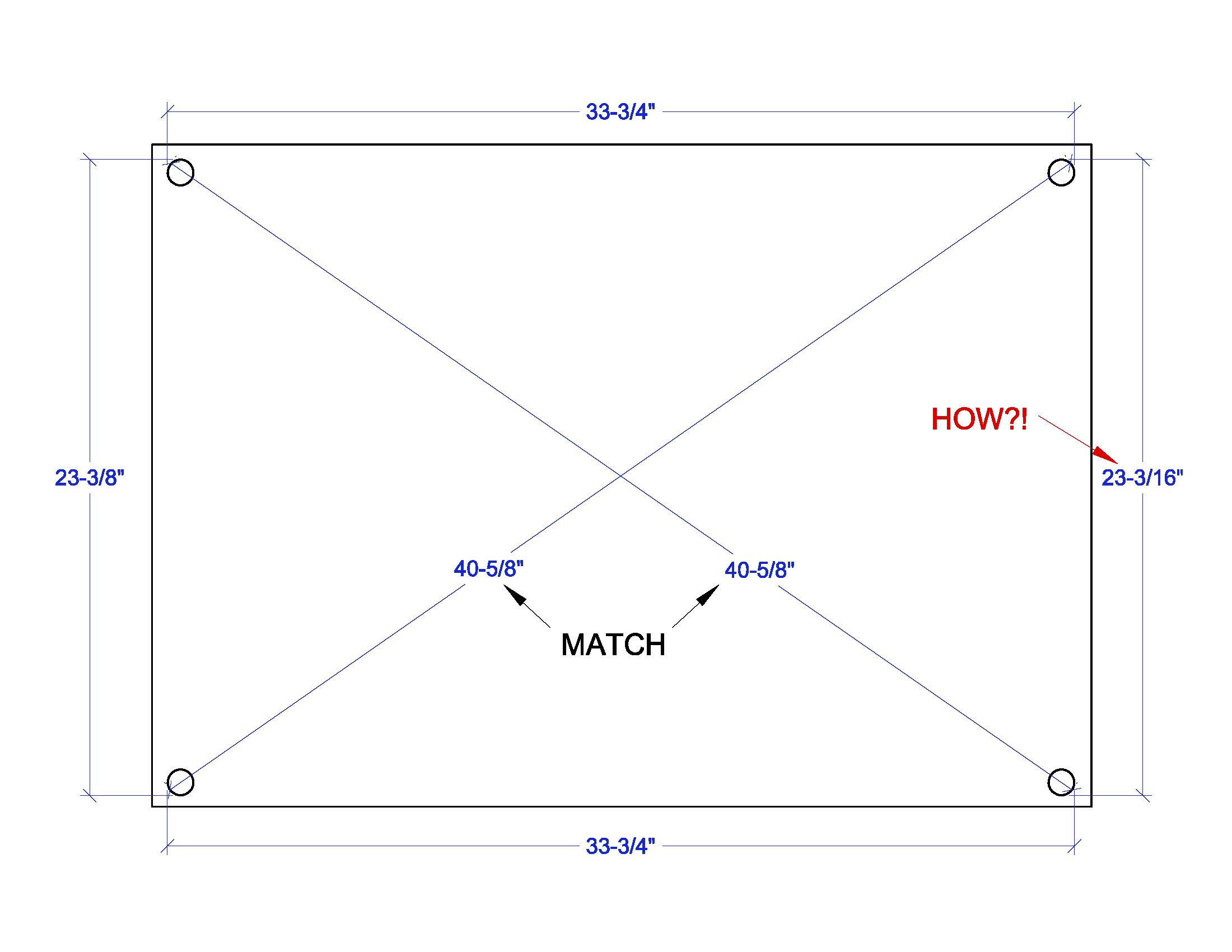
I’ve measured this this like 5 times, and this is what I get:
How can one dimension be nearly 1/4" different, when all the others match pretty much perfectly? I feel like this is at least most, if not the whole issue with the motion of the Y-Axis on this machine. If I can get all axes moving smoothly without power, then I’ll move onto choosing a control scheme and such.
A trapezoid would do that. You have to make sure the lengths traveled on both sides are the same before measuring the diagonals will work to measure square.
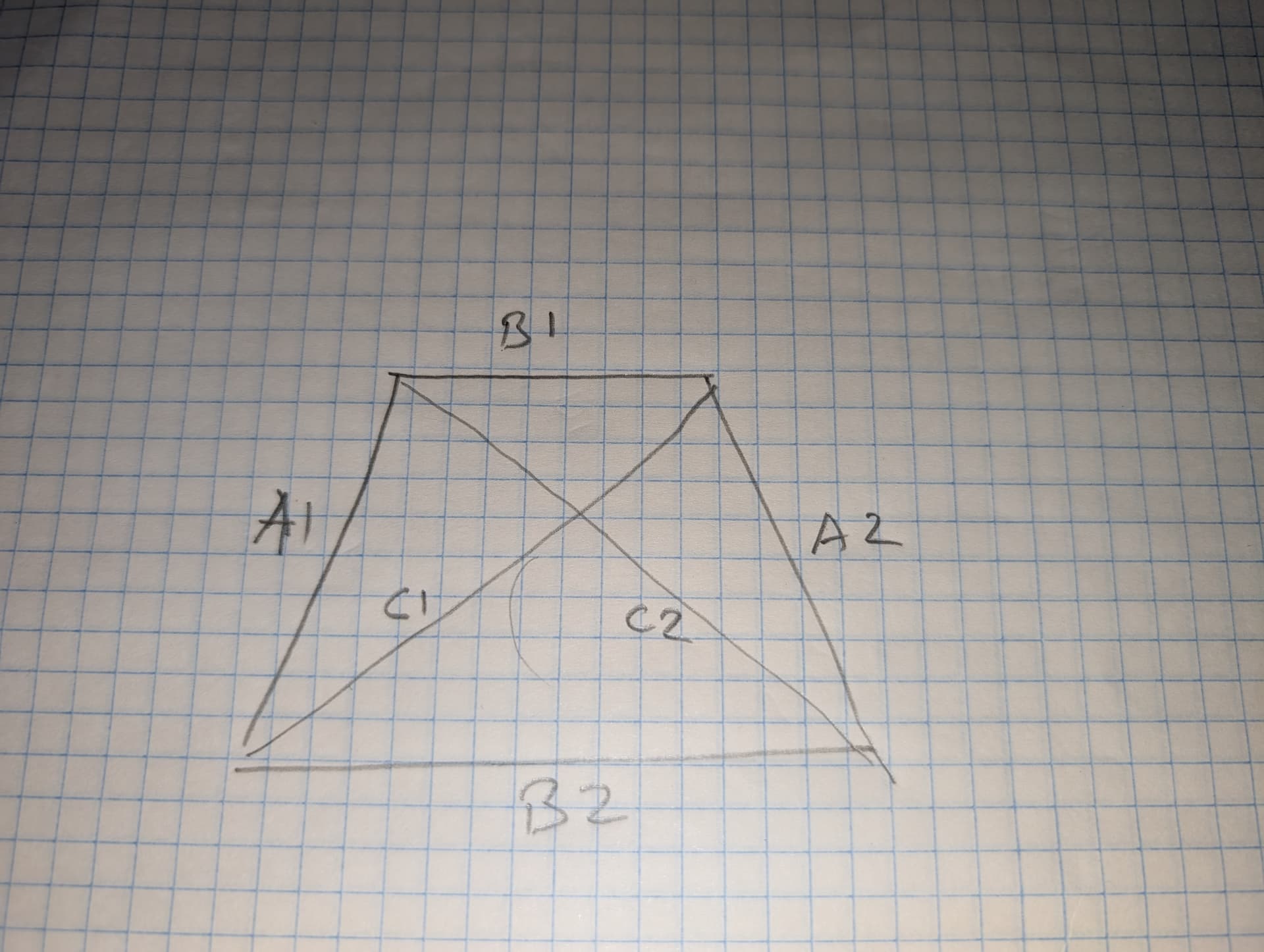
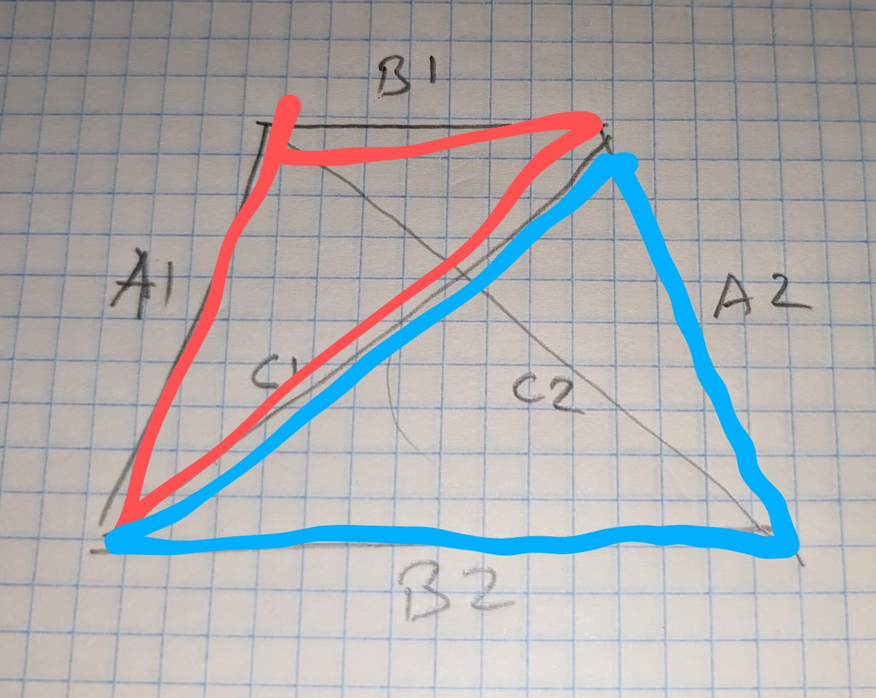
Comparing this to your drawing, A1 & A2 are 33 3/4, B1 is 23 3/16, B2 is 23 3/8, and C1 & C2 are 40 5/8
In effect, none of your angles are 90 degrees. I’m not a MPCNC expert, so I’ll leave it to someone else to tell you how to square things up. It might help others if you mention which axis is which (X & Y) in your above drawing.
From my basic trig days back in high school, it seems that if we look at this as 2 overlapping triangles, and if (using Bartman’s lettering) A1=A2 & C1=C2, then B1 has to equal C2. I don’t see mathematically how it can be otherwise. I’m wondering if the differences are just so small that I can’t measure it with my basic tape measure? I’m thinking no, since I can clearly see the difference in B2, and that should be magnified in C1 or C2, using the diagonal measurement method, right?
In any case, if someone can just tell me how to fix it, I won’t worry about the underlying math…
As Bartman noted your do not not have any right angles.
Easy way to do this is first make a right triangle. Side A will be the 23 3/8 tube for example, side B will be 33 3/4.
I changed to everything to decimal.
A=23.375 B= 33.75 C= 41.054
Using your Picture I chose the Bottom long side ‘33 3/4’ as the base point to start.
Set your measure tape for C at 41.054 inches and move the end of
A at 23.375 until the two cross. This gives you the first Right triangle. Now the the same with the other side. This time you will mark the 23 3/16 at 23 3/8 and move the end to make C measment
I’ll have to revisit this when I can think more clearly, I guess. I’m just not wrapping my head around the concept. Then again, I always did suck at math.
Thanks for the suggestions, guys. I’ll report back when I have an update, or more likely, additional questions.
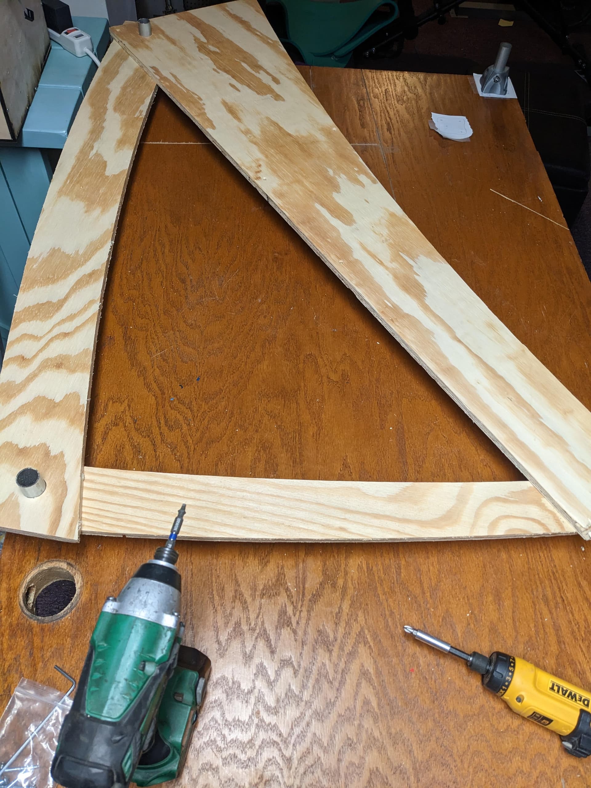
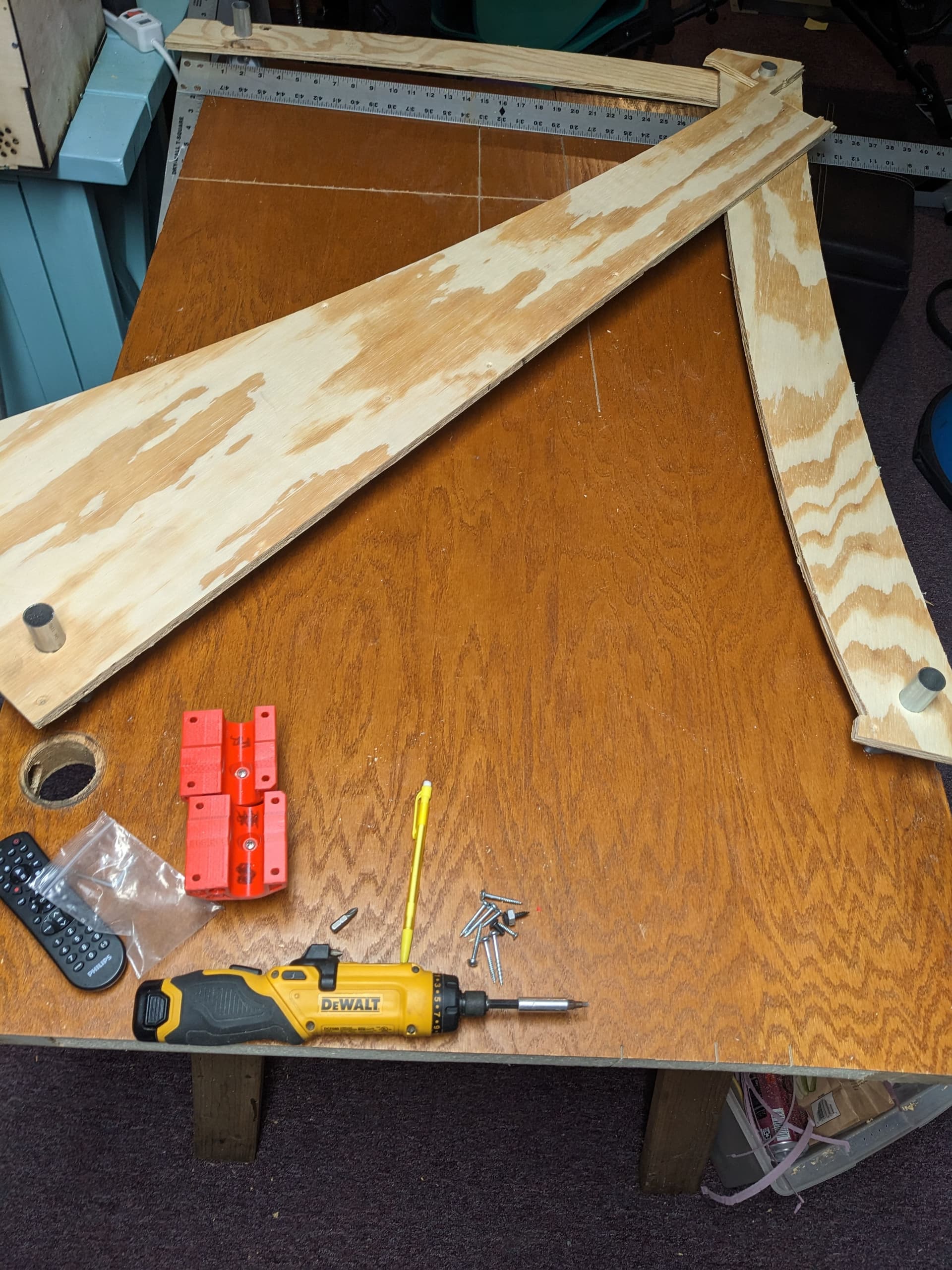
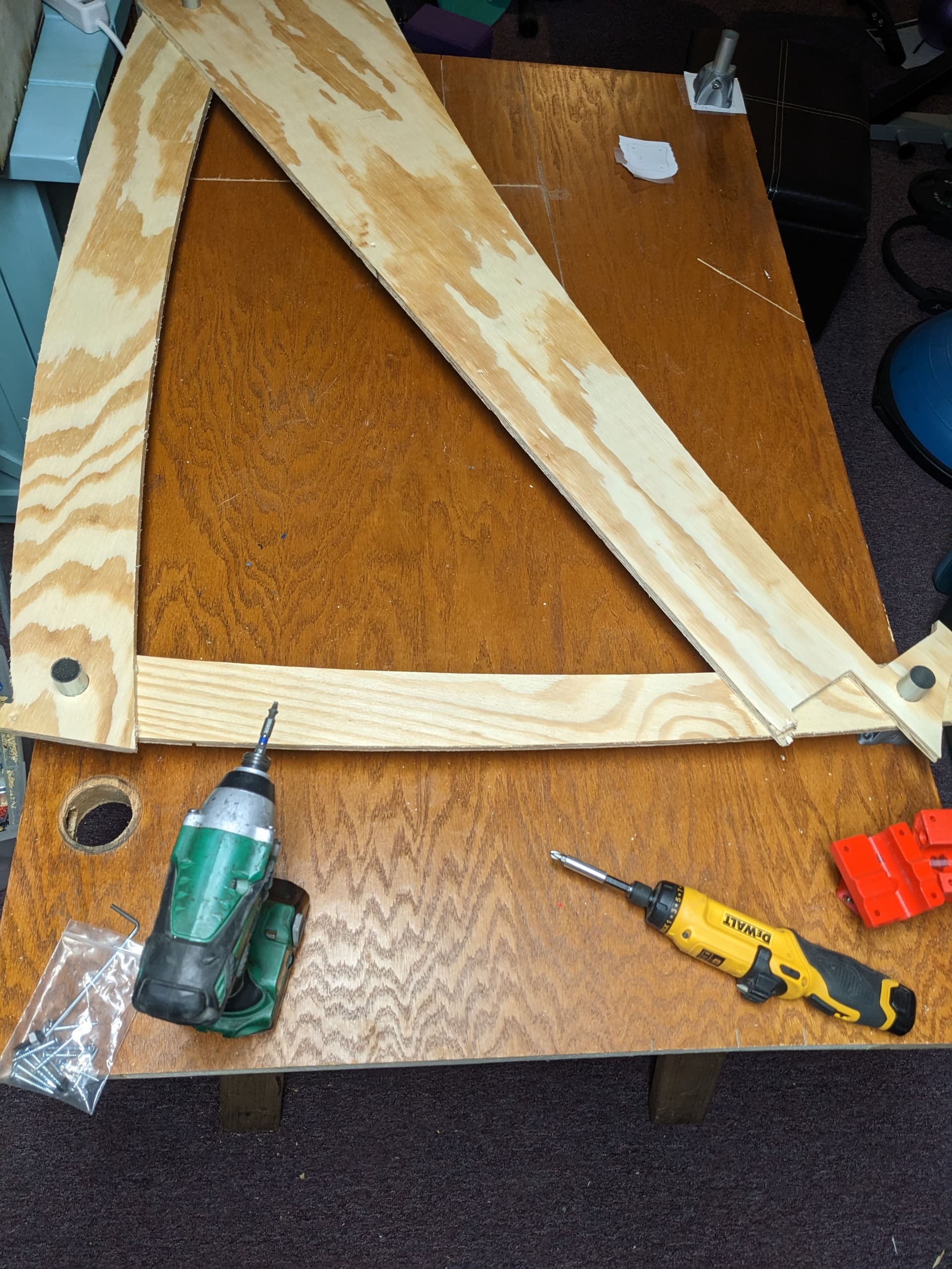
i made a couple spanners with a hole saw. One was for x, one for y and one for the triangle edge. Use all 3 as a triangle and screw them down. Then attach all to the 4th piece and it will be square.
I think you meant B2, but either way, that is incorrect. Nevermind the math, look at the drawing. B1 is clearly shorter than B2 and the rest are similar. You can easily draw this perfectly in CAD and see the same thing.
You’re correct, I did mean B2.
I’m saying that if you have 2 triangles, let’s call them Red and Blue.
If 2 sides of triangle Red are the same dimensions as 2 sides of triangle Blue, and they have equal interior angles, then the 3rd side of both triangles has to be the same.
Regardless, I’m going to try to move one of the feet to make B2 the same as B1, and see what effect that has on the other dims. In theory, it should throw them all out of kilter, but I think my ability to measure with any real level of precision is limited here, so it will probably appear to be very close.
Speaking of… how close to ‘perfect’ does this have to be? The documentation just says “get it as close as you can”. What does that mean? Within 1/4", or within 0.001"?
Using a tape measure to measure length, realistically you won’t ever be able to measure differences of 0.001", or anywhere close to that. And you should be able to measure closer than 1/4" unless you’re really bad with tools.
I use a metric tape, and shoot for around +/- 0.5 mm (around 0.020"). Note that getting less than 1 mm requires you to estimate between the lines. An Imperial (inches/feet) tape should get you within 1/32" (0.030") or 1/64" (0.015"), depending on the granularity of the tape.
If you’re measuring something less than around 8" (200 mm) in length, then a set of digital calipers can easily measure to 0.001" or 0.05 mm
Unfortunately, I have rather poor eyesight, even with correction, so that makes accurate measurement with a tape difficult.
I was able to get it squared up to within about 1/8" diagonal, by moving one of the feet. The table top is sort of chewed up, so I can’t position it any more accurately that this.
Putting the rails back in place, and moving the axes by hand, the chattering remains. I swear I think it’s worse.
My next step will be to check all the bearings to see if they are maybe binding or if one is loose or something.
This is turning out to be more of a rabbit hole than expected, but I’m learning how the machine goes together, which was kinda the point, so there’s that.
If these are your red and blue triangles, then you can see that the angles are not the same, so the sides don’t have to be the same. The angle between A1,B1 isn’t the same angle as A2,B2.
Weirdo.
Seriously, thanks for the explanation.
I think you missed a key phrase from my earlier post…
As you correctly stated, though, we have moved past this point.
I’ve got the base as squared as I’ll be able to, given the tools I have and my (limited) ability. At this point, I’m looking at other things as the cause for the chattering, such as sticky bearings, or maybe improper tension on the trucks.
I may have to tear it down a bit, and follow the documentation to build it back myself to see what went wrong… fun.
This week and next will be super busy, so I’m not sure how much time I’ll have to tinker. Hopefully I’ll get back to it before I forget what I learned from the earlier sessions…
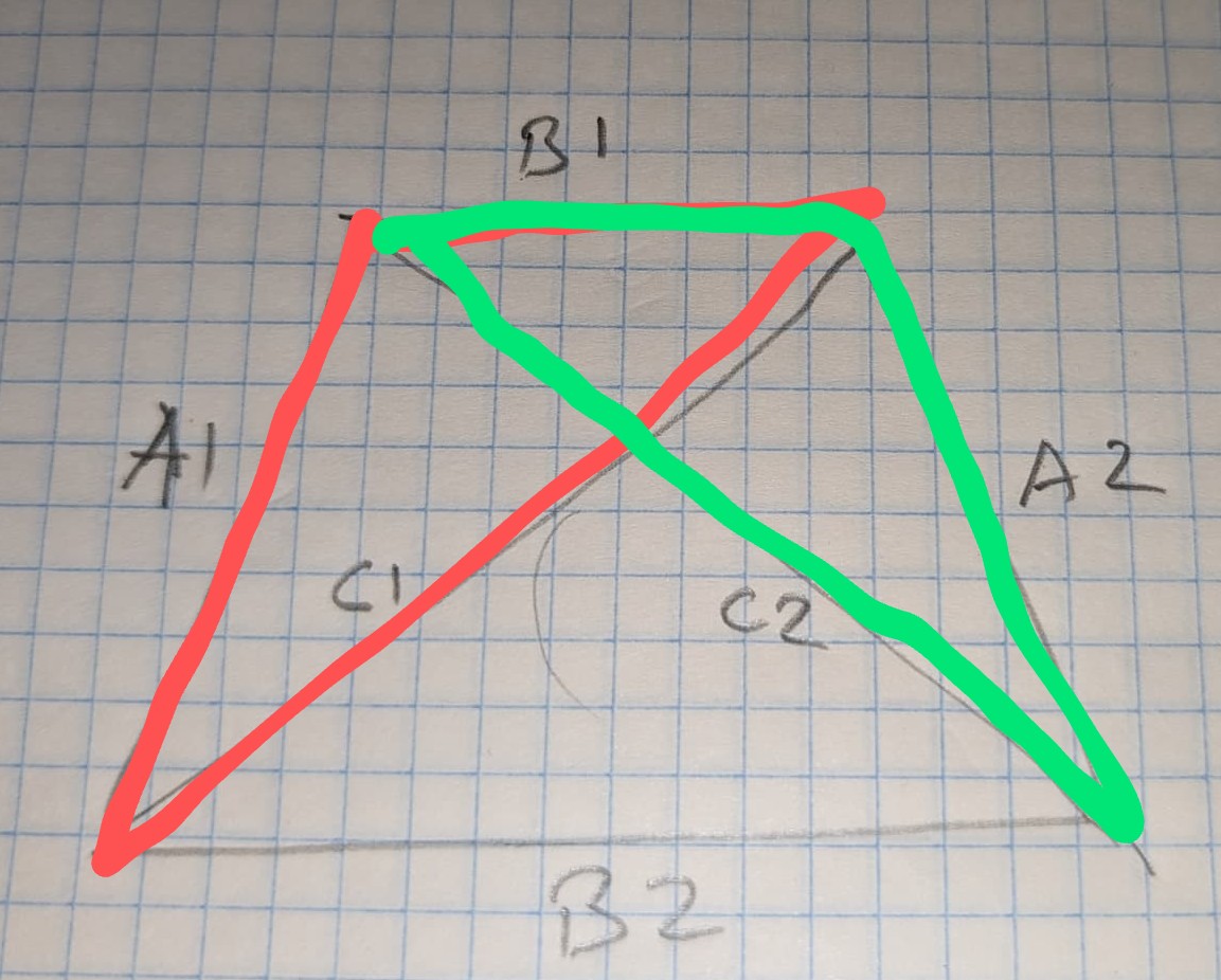
PS/EDIT: BTW, your diagram of the Red and Green triangles is exactly what I was describing. If those 2 triangles are the same, as you say, then B1 must equal B2.