Sure, no problem. How?
EDIT: I pulled the SD card out of the Jackpot and put it in the reader on my laptop, but it shows up as empty. What’s the secret to accessing the file system on these?
Sure, no problem. How?
EDIT: I pulled the SD card out of the Jackpot and put it in the reader on my laptop, but it shows up as empty. What’s the secret to accessing the file system on these?
The config.yaml file lives on the Flash onboard the ESP-32, not on SD.
You can use the web UI to download the config.yaml file to your machine, edit it there, then put it back.
Note- YAML files are very sensitive to spaces and formatting. I’d use wordpad if you’re on windows (not notepad) or any decent editor you have.
For the comments, just prepend a # in front of the endstops.
After this test, there will be a next step for us depending on what happens.
Do you have a DMM available?
Gotcha. I’ll look for that option, thanks.
Yep, got a fairly decent one. Good enough for basic measurements anyway. Now my skills in using it… that’s another matter. ![]()
I’ve downloaded the config.yaml, and opened it on my laptop for editing.
There doesn’t appear to be any reference to endstops in this file.
I’ve searched for “endstop”, “end” and “stop” with zero results.
What am I looking for?
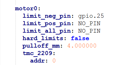
You’re looking for lines that have gpio.25, gpio.35, gpio.33, gpio.34, and gpio.32, as above, prefixed with “limit_neg_pin:”.
Umm…okay.
How on earth was I supposed to know that?! lol
Is there documentation for all this somewhere? I hate to keep asking what I feel must be obvious questions to you folks, but in the absence of any other resource….
I’ve tried basic Google searches, and come up with nothing. Maybe I’m just not using the right terms.
On each motor there will be a limit_neg_pin:
That is the one he is saying you need to comment out. There will be 5 of them. I believe you can just put # in front of it like this… #limit_neg_pin: but @MakerJim or someone smarter than me will need to clarify that.
Just keep asking here. We get it and have zero problems helping out!
I dunno, I only started using FluidNC for the first time yesterday… I was just going off your debug output and then read the MPCNC default config.yaml and saw that those pins are defined in the first line of each motor config.
Yep, I got em. I’m just wondering where I should have found that information!
Anyway, the endstops are commented out, the YAML file is uploaded back to the board, and everything is powered back up. Nothing has changed. One motor still moves, the other does not.
Here’s the kicker: If I swap the cables from the motors over to the Y-axis channels, both motors work perfectly, move in sync, and do not make any odd noises.
Clearly, we’re looking at a board issue, right? Could it be anything else?
I’ll willing to try whatever you guys think, but it seems pretty clear to me.
EDIT: Thanks @dos for those links. I hadn’t seen them before. Wait.. there’s a GUI v3?! ![]()
How do I know which one I’m seeing now? If there’s something newer/cleaner, I’d sure love to see it, since this UI is…. a mess.
For clarity, does this mean that you restarted or power cycled the board after uploading the new config. I would check the output of $SS to make sure that it picked up the change.
Sure it has… we’re working through the troubleshooting steps to get it working.
With the board powered down, swap the TMC2209 driver for the one that works and the one that doesn’t work. See if the problem moves or not.
You are most likely on V2. V3 is still a work in progress. @vicious1 is waiting for some changes to get pushed through in FluidNC before making V3 mainline. But its coming.
For now you are best to stay with what you have. Lets work one problem at a time.
This may have already been done up thread.
If no, then we see results.
if it’s already been done then our next step is to use a DMM to look at the step, enable, and Dir pins on the TMC 2209 where the associated motor isn’t moving.
there’s a really esoteric potential failure mode that we would be looking for.
Possibly. I did not go back and read through the rest before commenting.
Yes. Board was powered down and cold booted after yaml edits.
Correct. I’ve done that, twice. Noted most recently in post #193:
Since that swap doesn’t seem to make any difference, this leads me to believe the issue lies with the commands not being sent to the driver at all.
Next step is to bust out the DMM.
Tie the DMM - lead to jackpot VMOT power -
Use the + lead to compare the step, enable, and direction pins on the TMC2209 position that won’t move with its neighbors. Do this while commanding a large move so you can see what’s happening.
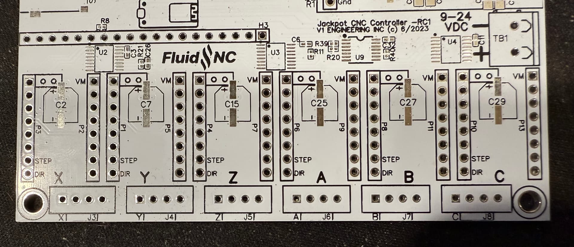
How do I identify those positions? Is there a pinout diagram somewhere?
EDIT: NVM, I think I found one, assuming this uses the standard pin mappings
It is screen printed on the board, but impossible to see with the drivers installed. See if this helps…
Edit… Step and Direction are easy. I’m not sure which one would be enable. Hopefully what you found tells you or @makerjim knows
I set up the DMM as noted by @MakerJim, with the - DMM Lead on the [-] terminal of the Jackpot.
I then probed each of the specified points on the 2 X-axis driver modules (and the Z-axis as well, as a “control”).
Results:
Please note that unless otherwise noted, all voltages are constant, meaning that they did not change between periods of carriage motion and idle.
Jog X+
Enable = 6.5mV
Step = 0.7mV (idle) - 6.3mV (moving)
Dir = 0.00V
Jog X-
Enable = 6.5mV
Step = 0.7mV (idle) - 6.3mV (moving)
Dir = 3.26V
Z-Axis + (for control)
Enable = 6.5mV
Step = 0.7mV (idle) - 3.0mV (moving)
Dir = 3.26V
Z-Axis - (for control)
Enable = 6.5mV
Step = 0.7mV (idle) - 3.0mV (moving)
Dir = 0.00V
ALL drivers reported the exact same output numbers and behaviors.
That’s why I didn’t report them separately, above.
The only variation was that the Z-axis had a lower max V under moving load.
Anyone else super extra confused?