It’s these cables: Amazon.com
That is a classic symptom of an open wire to the stepper. I’m guessing that the cables aren’t the same pinout as the originals.
The cables you linked are actually longer replacement cables, not extension cables. The extension cables would have 4 or 6 pin DuPont connectors (M on one end, F on the other) that simply plug into your existing stepper motor cables.
If you are handy, you could use a DMM (Ohmmeter) to meter out the existing cables, and then swap the pinouts on your new cables to match (as . It’s a bit tricky, but there are lots of videos on YouTube that could show you how to remove the pins from the DuPont connectors to swap the pinouts.
Or you could order extension cables rather than replacement cable, and connect them to the DuPont end of your existing cables
1 Like
I’d love to, but these are the only ones I could find that had the correct plugs on either end, and were long enough (2M) for my needs. If anyone is able to find extension cables that are at least 4’ long on Amazon, I’d love to swap them out.
To be clear, though. I need cables that have the stepper plugs (XH2.54) on one end, or they won’t do me any good. I already have the cables I got from X1E going from the Jackpot, they just aren’t long enough to reach the motors.
Yes, but your original cables also have the stepper plugs on one end, and DuPont on the other. All you need to do is get some extension cables that plug into the DuPont connectors on the original cable on one end, and to the DuPont connectors on the Jackpot board at the other…
2 Likes
Changing the order of the wires is really easy. Use a pin or exacto blade to pry the plastic tabs up a little and the terminals slide right out.
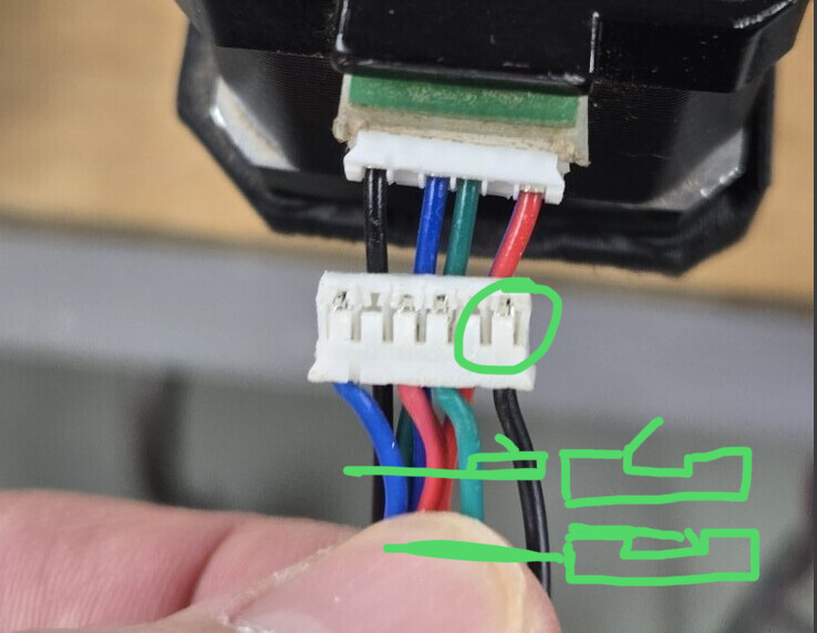
Then push the tab back down into place. You’ll see the terminals have a little barb on one side that faces towards the tab so when you slide it back in you should feel a positive click.
6 Likes
I think this is the best description I’ve seen of how to do the pin change. The green on the lower right makes it. Very nice!
1 Like
That is an excellent description. But I usually don’t bend the tab back that much. I just slide the tip of a knife in that gap and that lets the barb go past the plastic tab.
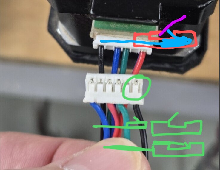
Here, the purple knife tip allows the blue barb to go past the red tab.
4 Likes
except that the reason I’m replacing the original cables is that I don’t trust them. I think one or more may be faulty, causing the motion issues I was experiencing before I swapped to the latest replacement cables from Amazon, which don’t work at all.
Those are the extenders I currently have installed, but they aren’t long enough, and don’t have the correct plug on one end. Now, I understand that this is because they are extension cables, not stepper cables. Duh. lol
@jeffeb3 & @Dreyfus, thank you both! That’s an excellent description, and the graphics are super helpful. I may break out my magnifiers and give that a shot. Nothing to lose, right? ![]()
3 Likes
Nothing at all to lose.
Knowledge, experience, and maybe a fixed machine all potentially to gain.
3 Likes
Ok, I think there’s definitely (maybe) something amiss with this Jackpot board. ![]()
Check my process here, please, and tell me if I’ve missed something obvious…
I made up new cables (using the excellent instructions above) for just the X-axis, as a test.
Right now, only the 2 X-axis motors and the Z-axis are connected to the Jackpot.
When powered up, and jog commends sent on X, only the X1 motor responds.
The Z-axis moves fine.
I’ve tried both the new cables I just made, and the original cables, and the result is the same.
Just as a triple-check, I swapped the X0 and Y1 stepper driver modules, just to see if that could possibly be the issue. It was not. I’m still only getting motor action on X1.
I’m baffled at this point. Other than the board not sending a “move” signal to the X0 channel, what could be going on here?
EDIT: Just to be clear, I know that both the cables and steppers are functional, because I swapped the X0 and X1 channels on the board, and then X0 worked and X1 did not.
Is your config still the same as in post 152?
Every time we troubleshoot one of these machines, we’ll ask for a similar starting point.
Give us a fresh output of $SS
Then, walk through each endstop and verify they are all working correctly with $Limits
With those results in hand, we’ll suggest next steps, which will likely include measuring the coil resistance looking into the harness where it plugs into the jackpot.
I’ll grab that next time I get out to the shop…
We covered this before, but I realize it’s been a while. There are no endstops installed on this machine…yet. That’s coming, once we sort out these other issues.
I can’t see how that would be relevant, since both stepper motors work properly when I swap the channels on the board. Perhaps I’m missing a common fault?
Did you edit the config.yaml to take the endstops out?
No, first I’ve heard of that. There’s no mention of that in the documentation, that I saw…
Would that effect the basic function of the machine?
Here’s the latest $SS output, as currently configured.
This is with only the X and Z axes connected to the Jackpot, and the driver controller modules are still swapped between X0 and Y1. Also, the X0 and X1 cables are backwards on the board, not that it really matters, but it means that only motor X0 (on channel X1) is responding.
$ss
[MSG:INFO: FluidNC v3.9.1 https://github.com/bdring/FluidNC]
[MSG:INFO: Compiled with ESP32 SDK:v4.4.7-dirty]
[MSG:INFO: Local filesystem type is littlefs]
[MSG:INFO: Configuration file:config.yaml]
[MSG:INFO: Machine MPCNC]
[MSG:INFO: Board Jackpot TMC2209]
[MSG:INFO: UART1 Tx:gpio.0 Rx:gpio.4 RTS:NO_PIN Baud:115200]
[MSG:INFO: I2SO BCK:gpio.22 WS:gpio.17 DATA:gpio.21]
[MSG:INFO: SPI SCK:gpio.18 MOSI:gpio.23 MISO:gpio.19]
[MSG:INFO: SD Card cs_pin:gpio.5 detect:NO_PIN freq:20000000]
[MSG:INFO: Stepping:I2S_STATIC Pulse:2us Dsbl Delay:0us Dir Delay:1us Idle Delay:255ms]
[MSG:INFO: User Digital Output: 0 on Pin:gpio.26]
[MSG:INFO: User Digital Output: 1 on Pin:gpio.27]
[MSG:INFO: Axis count 3]
[MSG:INFO: Axis X (3.000,1223.000)]
[MSG:INFO:   Motor0]
[MSG:INFO:     tmc_2209 UART1 Addr:0 CS:NO_PIN Step:I2SO.2 Dir:I2SO.1 Disable:I2SO.0 R:0.110]
[MSG:INFO:  X Neg Limit gpio.25]
[MSG:INFO:   Motor1]
[MSG:INFO:     tmc_2209 UART1 Addr:3 CS:I2SO.14 Step:I2SO.13 Dir:I2SO.12 Disable:I2SO.15 R:0.110]
[MSG:INFO:  X2 Neg Limit gpio.35]
[MSG:INFO: Axis Y (3.000,2443.000)]
[MSG:INFO:   Motor0]
[MSG:INFO:     tmc_2209 UART1 Addr:1 CS:NO_PIN Step:I2SO.5 Dir:I2SO.4 Disable:I2SO.7 R:0.110]
[MSG:INFO:  Y Neg Limit gpio.33]
[MSG:INFO:   Motor1]
[MSG:INFO:     tmc_2209 UART1 Addr:3 CS:I2SO.19 Step:I2SO.18 Dir:I2SO.17 Disable:I2SO.16 R:0.110]
[MSG:INFO:  Y2 Neg Limit gpio.34]
[MSG:INFO: Axis Z (-100.000,200.000)]
[MSG:INFO:   Motor0]
[MSG:INFO:     tmc_2209 UART1 Addr:2 CS:NO_PIN Step:I2SO.10 Dir:I2SO.9 Disable:I2SO.8 R:0.110]
[MSG:INFO:  Z Neg Limit gpio.32:low]
[MSG:INFO: X Axis driver test passed]
[MSG:INFO: X2 Axis driver test passed]
[MSG:INFO: Y Axis driver test passed]
[MSG:INFO: Y2 Axis driver test passed]
[MSG:INFO: Z Axis driver test passed]
[MSG:INFO: Kinematic system: Cartesian]
[MSG:INFO: STA SSID is not set]
[MSG:INFO: AP SSID FluidNC IP 192.168.0.1 mask 255.255.255.0 channel 1]
[MSG:INFO: AP started]
[MSG:INFO: WiFi on]
[MSG:INFO: Captive Portal Started]
[MSG:INFO: HTTP started on port 80]
[MSG:INFO: Telnet started on port 23]
[MSG:INFO: Flood coolant gpio.2]
[MSG:INFO: Mist coolant gpio.16]
[MSG:INFO: Probe gpio.36:low]
ok
Humor me.
Comment out all the limit switches in your config.yaml, reboot, try motion again.