Yep. We’ll keep helping you as you take each step.
Do you have a good DMM?
I make little test probes from M-M headers, then use those as probes. Later today I’ll post a better write up of what I do.
Yep. We’ll keep helping you as you take each step.
Do you have a good DMM?
I make little test probes from M-M headers, then use those as probes. Later today I’ll post a better write up of what I do.
I do. I have some M-M pin cables also, so I could make up probes like you talk about also.
If you’re willing to write it up, I test it our for sure, thanks!
In the meantime, my new extension cables should be here tomorrow. I’ll have time (I hope) on Wednesday evening to swap them out, which will eliminate a bad cable, since then I’ll have all new cabling between the Jackpot and the motors. If it’s still not sending signals to one motor, then I’ll have to trace it out to see what’s going on.
While I’m waiting for the cables to come, can anyone suggest software that I need to get loaded on my laptop for controlling this thing once it’s working?
I have the ESP323D GUI for basic jogs and testing, but what do you all use for actual design and cutting jobs?
For design, Autodesk Fusion (formerly Fusion 360) has a free hobby license. You still have to register and apply (don’t sign up for the free 30 day trial - that is for the paid license). The learning curve is somewhat steep, but much easier than learning FreeCAD (IMO), the other free design software option.
There are some other options (Sketchup, OpenSCAD, others) that I’m not familiar with, maybe others can chime in.
For creating the g-code, EstlCAM seems to be the go to favorite here. It has a free option, but after a few uses a popup window timer appears whenever you output the g-code to a file. The permanent license is only $59 USD or 49 Euro. Worth it IMO (and I am a cheap bastard). It’s pretty intuitive. User instructions/manual are a bit lacking, but there is a ton of info on this forum, and lots of members here that use it that can lend a hand if you have questions.
Ugh, I hate Fusion. lol
I use Solidworks some (got access through work), but I mostly use AutoCAD and Lightburn for my laser. Will those work for CNC, or is it a different animal?
I’ve heard good things about EstlCAM. I’ll definitely look into getting a license, if I can get the machine into a state of basic functionality. $60 for a license is nothing.
As long as it can output a 2D drawing (DXF, SVG, etc.), then it should be fine
You guys are using Fusion to create 2D drawings? Why?!
I thought there was something in Fusion that was CAM-specific. If it’s just for 2D drafting, there are SO many other, much better options.
And yes, I’m pretty sure that AutoCAD (the originator of the DWG and DXF formats) can output the proper filetypes. lol
People who are using fusion… Use fusion.
Same with OnShape, or FreeCad, or OpenSCAD, or whatever.
EstlCAM is a really good CAM option for these machines, and is commonly used.
For folks that are regular users of F360, the F360 CAM may be their best option.
I tried this (I have educator access to all the major packages), I hated it.
Actually I do this quite often.
Not just to make a 2D drawing, but making assemblies, parts that need to fit together to make something more complicated than a 2D cutout, then export the 2D drawings to make 2D (or 2.5D) parts which assemble into a whole.
Sometimes parts to connect are entirely 3D and will be 3D printed and fastened to the 2D parts.
I also tend to fall into the mindset of “if your tool is a hammer, make all of your projects look lime nails.”
I used to use FreeCAD, as the “personal.use” license for Fusion majes me uncomfortable. too many Free Personal licenses have been turned into “paid license only” in my past, so I resisted. However, there are rhings that Fusion does that were difficult with FreeCAD, and I switched, but that meant switching everything. So I design stuff for 3D printing, 2D cutting, whatever, using the same tool.
One day I may go back to FreeCAD, it’s had a couple of revisions since I last used it, and it may be more suitable for me now.
This!!!
Plus making 3D printed parts (modifying LR parts, creating new 3D designs, etc.)
Those are all relevant points, I guess.
I don’t understand the point about using a 3D modeling tool to make 2D parts…that then get assembled into a 3D assembly. I’m not saying I disagree, I literally don’t understand. ![]()
I’d like to, and maybe once I get into this a bit more, it will all make more sense.
At the moment, I (kinda) know the 2D laser cutting world, and the 3D modeling for 3D printing world, so I’m having a bit of a tough time mentally grasping the 2.5D workflow. I’m sure it will all make much more sense once I start doing it. Thanks for the explanations and examples!
Here’s an example.
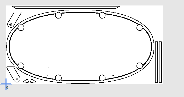
In my case, I’m making a custom shaped poker table with a super-ellipsoid shape. I want to be able to change the length, width and shape (n value) of the curve using parameters. I want to also be able to change features like number of cup holders (which affects placement angle), width of the padded rail, height of raised rail, etc. If any parameter changes, it affects a multitude of other dimensions.
The table is made from 2 or 3 sheets of plywood, with holes in each layer that must line up exactly with each other. Then there are minor attachments like bottom layer support gussets and “kickstands” (legs that support the table when it is stored on it’s edge), all of which can change position when other parameters change.
All of this can’t be adequately represented in 2D. I need to create a 3D model that shows all of the components and how they relate to each other. Then I need to change various parameters to determine if there is any overlapping parts and/or other types of conflicts with all of the independent parts.
")
Then, once everything is confirmed to work together, I select the various parameters for the size and shape of table that I want to cut, and export the individual layers and components as DXF files and use EstlCAM to cut them out.
I’m always willing to give something better a try - what are you thinking of that is good for dxf layouts?
I don’t see anyone mentioned it yet but there is no lightburn for cnc… yet - they’re working on it but (in my opinion) there’s a looog way to go. It’s missing some basic functionality and the UI isn’t on a par with lightburn. But it’s still in development so keep your fingers crossed.
Librecad is the closest to the old school 2D autocad that I have found.
That said, since I have learned OnShape, I use it for 2D. The way a modern sketch gets built just makes more sense for me now that my brain has been trained to think in constraints.
Well that’s just…impressive! Wow, thanks for sharing. That really does help me visualize how a 3D model can assist with cutting 2D shapes.
Really? I thought Lightburn did work for CNC? That was going to be one of my suggestions. For basic design/layout work, there’s NanoCAD and LibreCAD.
If you want something more robust, but not free, BricsCAD is well-regarded.
OnShape looks great, but not for me. I just don’t get the mindset of whoever sets pricing for OnShape and similar software.
Free $0 means all your docs are free and public. A non starter for me.
Then jumps up to $1500, also a non starter for me.
I haven’t bothered to spend time learning OnShape properly/deeply because of the pricing and free sku resulting in no control over personal data/IP. Seems like a screwed up overly coarse pricing model to me if their goal is to increase revenue and growth.
Am using Fusion 360 FREE for 2D, 2.5D and 3D modeling. Partly out of habit/familiarity at this point. I’m not claiming it’s the best tool for 2D. It’s the tool I best know how to use for these types of tasks. I appreciate their parametric expression constraint based sketch features, with support for python/C++ script add-ins.
That said, lately, I’ve spent many many hours making OpenScad based parametric weather strip seals ![]() . I could have achieved the same task in Fusion 360 much faster, but I want the resulting model to be customizable/parametric within a webpage without using server/service resources.
. I could have achieved the same task in Fusion 360 much faster, but I want the resulting model to be customizable/parametric within a webpage without using server/service resources.
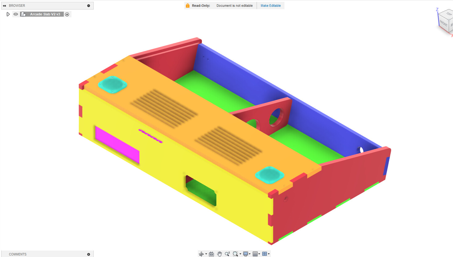
If you look, you’ll see some pink bits “sticking out” the back. Those are from the model of the ATX motherboard, and represent the card slots. Since I did not need room for any expansion cards for this project, I did not need to cut the holes for them, so I did not, but I did need/want the opening for the motherboard, and of course mounting holes in the bottom piece for the stand-offs.
The speaker grilles are 3D printed, but mount through the top panel to the speakers below them. The center brace has mounting points for 2.5" and 3.5" hard drives, as I wasn’t sure which I would be using when I started building. (I went with a 3.5")
I went a bit nuts with the colours for this model. I usually don’t but it was to make it really clear how parts were going to be assembled, sand how much clearance I was going to have for controls.
Yes, I could have done it all with 2D drawings for the cutting, and of course every one of those panels has a 2D sketch associated with it, which was exported to a DXF for cutting.
Millmage does CNC. But is in VERY early stages. It is great for plywood work, but no V carve or 3d carving yet.
I have used so many things that someone shared for free on the Internet. Sharing my crappy drawings is NBD to me. It’s honestly preferable. I just wish I knew if anyone actually sees it.
No Linux option, which is a non starter for me. I don’t use windows. I won’t pay for a mac.
You guys know the saying “can’t win for losing”?
That’s how I feel right now. ![]()
I got in my new extension cables, and ran them this evening.
I fired up the web GUI, and … now nothing works.
My X & Y axes both refuse to travel. They just sort of shiver back and forth, when issued a jog command.
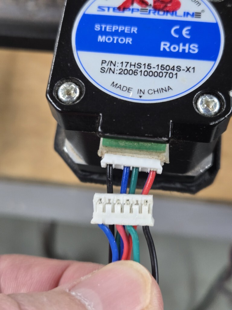
I think the problem may be that these new cables aren’t the same color order as the ones I replaced, although I can’t really see how that would matter. It’s not like the stepper can see the color of the wires. lol
See this image:
“The terrible thing about standards is everyone has their own”
There are multiple ways that motor vendors have wired the connectors on the stepper motors.
You have a cable that was designed for a different termination order than your stepper motors, or for a different pinout at the controller.
Options-
You could re-pin the connectors (release the tabs on the metal contacts, remove, reinsert)
You could order extension cables with the correct pinout.
You might be able to fix it by rewiring the opposite end of the cable (which again means you have to de-pin and re-pin the connector)
What does the opposite end of that extension cable look like?