Love the modularity. There was a 3D printer a few years back that had a similar modular design where it used identical pre-built motion units that were just assembled into a full XYZ system…maybe snapmaker? I just remember seeing a review on some 3D printing channel where they were surprised at how it just re-used the same building block for all of the axes.
1 Like
Thanks, guys, for the kind words. I’m doing fit-checks right now and see that I have to design in more allowance for parts that should fit tightly together… ala the light blue stepper “cage” that fits through both the silver carriage/roller halves. I’m having to scrape all the surfaces that must mate… and it ain’t much fun. I’ll have to go back into Onshape and adjust things so that scraping and filing won’t be necessary… ![]()
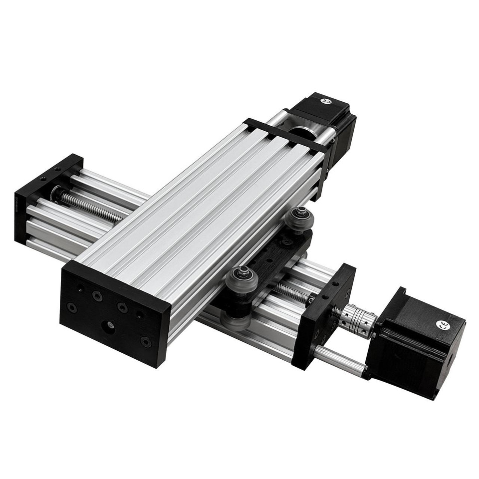
OpenBuilds designs and sells modular linear stages that can be stacked together in various ways to get multi-axis motion…
2 Likes
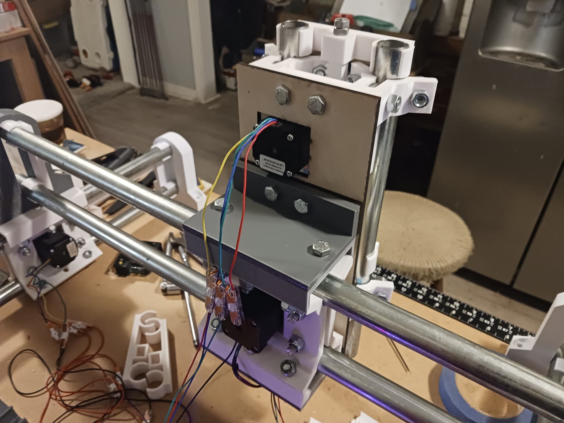
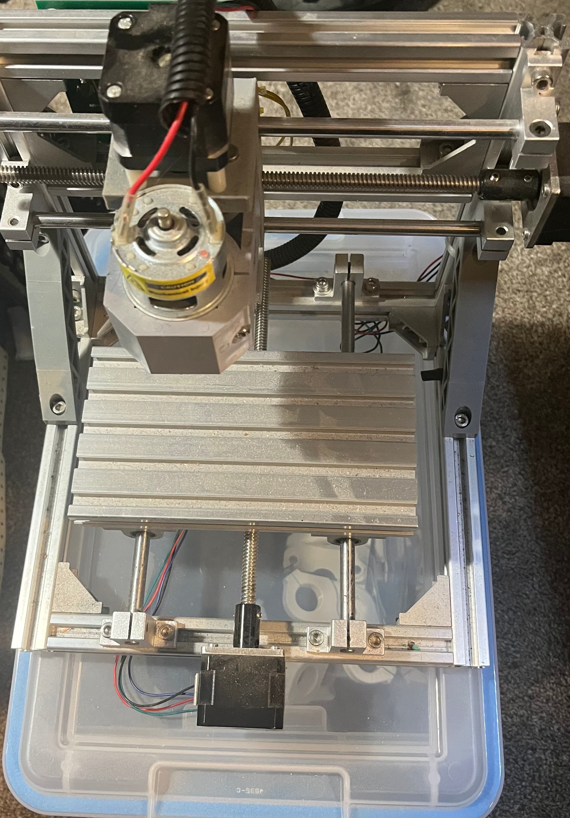
I’ve printed all parts and have assembled and tested the identical linear stages for the X- and Y-axis of MPR&P machine. I’m printing the last gantry support piece to allow for stacking…

I’ve also uploaded the STLs to Printables website should anyone be interested in playing around with it. It’s still a work in progress but any changes to the X- and Y-stages going forward should be relatively minor. The Z-axis is still being worked… ![]()
–David
5 Likes
Stacked and air-milling a drawing…

I’m now printing some 20-tooth rack segments to expand the Y-axis to better fit the worktable and give a little bigger workarea. Also have an idea for better attaching the Z-axis to the gantry…
– David
5 Likes
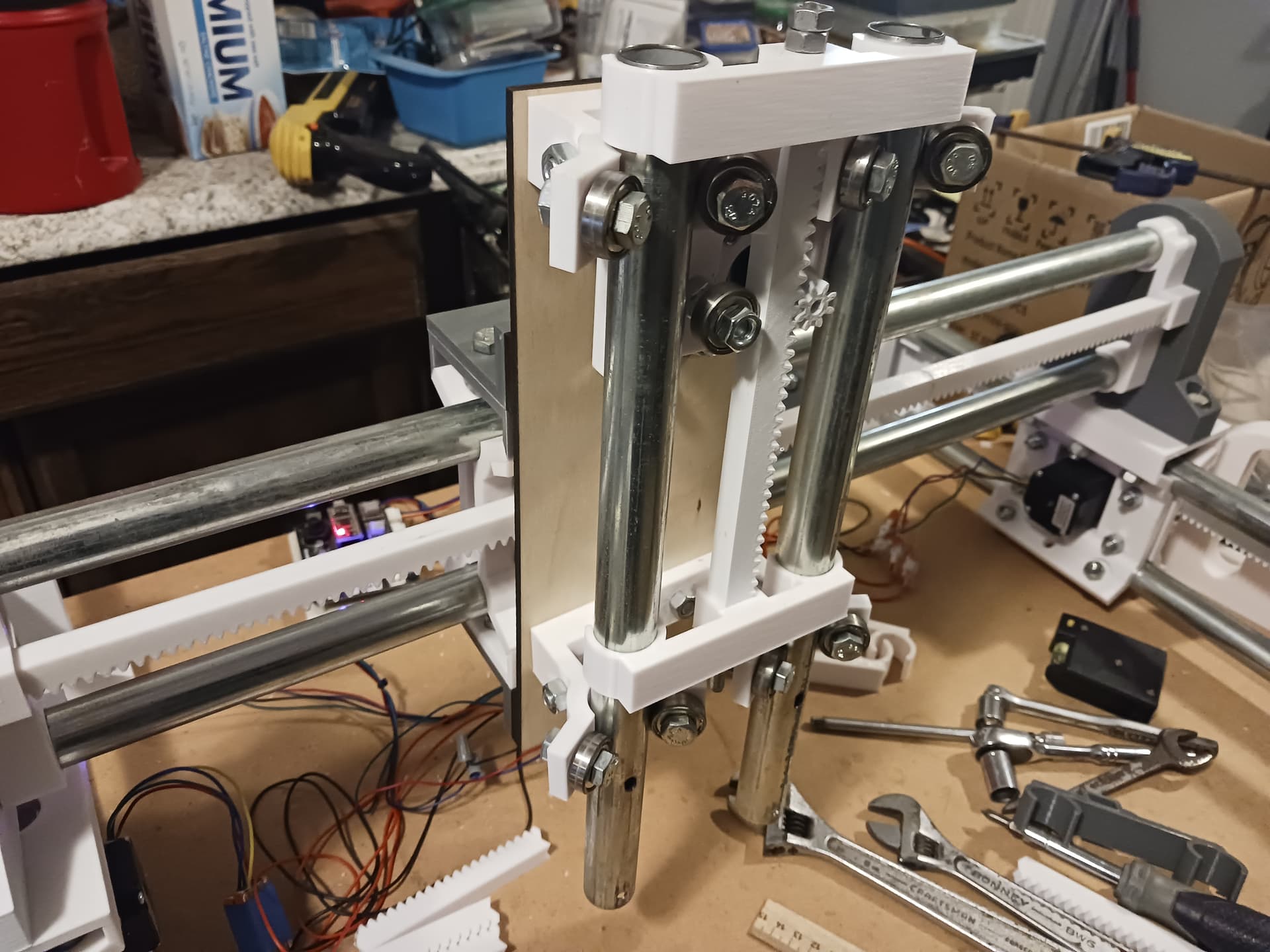
As much as I wanted it, I’ve been unable to make the Z-axis “identical” to the other 3 linear stages. I’ve reverted to a reworked Z-stage shown earlier in the thread when I did the pen-plotting…

I’m gonna admit “defeat” on my efforts to make the Z-axis identical to the others. The anti-clamshell roller halves of the other stages just don’t lend themselves to easily interfacing at right angles to the gantry carriage and I’ve already spent twice as much time trying make it fit than I did on the entire X-Y portion of the machine. But the machine is indeed R&P throughout and fully three-axis, so I’m good with that.
I’ll put the required parts for the Z-axis I’ve settled on out on Printables for completeness sake. I did laser-cut the Z-backplate and a couple of shims but it is otherwise completely 3d-printed and built from my MPCNC-centric junkbox. The 1/4" threaded rod for the racks is the only thing I purchased specifically for this project… so less than $20 out of pocket, for sure.
I hope this has been of interest to somebody… I’ve had fun doing it. Thanks to Jim, Ryan, and all others who’ve offered up words of encouragement to keep at it. I do think printed R&P has “potential” for DIY machines… but it’s gonna take some folks with far more talent and expertise to take it further and truly test it to its limits. If there are any questions, I’ll be happy to share what I did to put this machine together.
Enjoy.
– David
6 Likes
Do you think R&P has performative differences vs belts? Apart from being very cool of course.
This guy uses R&P for his machine and it is awesome (video starts at the relevant part):

2 Likes
There are obviously different sourcing options for R&P. I think the biggest difference is that you can easily buy belts.
There will be different specs for backlash and tolerances. The stretch of the belts is minimal, but non existent with R&P. Any printed gears are only going to be as accurate as the printer that made them. There may be a case to say R&P would move less under load. The trouble is being able to reliably build them to have similar backlash and tolerance to the belts.
2 Likes
I’ve personally not seen any difference. The rulers I’ve lasered and plotted with this machine seem every bit as accurate as any I’ve ever done with previous belted-driven machines. The calibration procedures I used allowed me to adjust the steps/mm setting in Grbl to get ruler accuracy quite comparable to a commercial steel ruler… and there is a noticeable difference between 152 steps/mm and 152.88 steps/mm with the printed R&P parts on this particular machine.
This and other R&P driven machines I’ve built have never been heavily used enough to determine the effects of wear and tear. And what little I have used them, I’ve never seen any observable decrease in performance. I’ve been encouraged to hear Jim and Jason and Philipp all testify in this thread to seeing machines with printed gears and cams that have been used heavily and are still in good shape. Hopefully, that’ll be the case here.
I have a Prusa MK3S that’s served me virtually trouble-free now for 5+ years… and a Prusa MK2S before that and now belongs to my SIL. And even before that, I had a couple of FolgerTech kit-built machines that were NOT so trouble-free and user-friendly… and it was far harder and “fiddly” to get good prints from them. I’m far from being an expert on 3d-printing but have always been quite satisfied with the prints I’ve gotten from my Prusa machines. The printed parts have always fit quite well with each other and the store-bought hardware that holds them together. I also insure that I print all the rack and pinion parts together on one or two build plates… and all on the same machine and from the same gcode. While an “expert” might quibble over the cosmetics of some of my parts… functionally they almost always work as intended. And I agree, Jeff… my pre-Prusa machines would probably not have produced parts as accurate and well-fitting.
1 Like
I’m going to start working on a make from the Printables repository starting this weekend.
Looking forward to playing with a fun, modular system.
1 Like
Wow, Jim!
I’m really thinking that there should be a relatively simple way to clamp/fasten/glue/etc. printed parts to the conduit and each other. Holes in the conduit clips and conduit to fasten them together with sheet metal screws, bolts through the slotted end supports to pull the slot slightly together to clamp conduit, etc… that sort of thing. If this machine should ever be required to carry anything more than a laser or pen, it can’t be free-standing and needs to be stiffened up.
It would be great if the existing STLs could still be used and I’m hesitant at this point to go in and modify parts to accommodate pins/screws/bolts… without giving it more thought and discussing it with you guys as to how best to go about stiffening it up. It’s good enough free-standing for what I need – laser and pen – but I think it really needs to be given some attention for anything more serious.
Any thoughts/suggestions? What do you envision doing with a machine like this?
I was toying with the idea of adding a pen, maybe a laser (but not a laser to take to a show.)
2 Likes
If all you are doing is laser or pen the STLs on Printables should be fine then. I’ll get on the stick and get the Z-axis parts added to the page. I didn’t actually do a tool mount yet but a clip-on version could be done pretty easily…
I sent you a DM inquiring how I might best be of help…
Responded in kind, we’ll see what I can build and what comes of it. Mostly looking to have fun trying another community members experiment and see first hand how it works.
It’s to keep the creative thinking flowing.
I did some sorting through my parts bin, so in the spirit of it will use as many of my existing items as possible. Had a blast just doing that.
2 Likes
Just an update, I haven’t started printing anything and won’t until the weekend.
I have gone through my old parts bin, and I’ve settled on using motors that are left over from the old LulzBot AO10X printers. They were originally LulzBot factory print farm machines, then donated to a local makerspace, and when that farm got upgraded members purchased those. I ended up with a couple. Might be “underpowered” for CNC but will be quite all right for a CNC pen/laser/demo machine.
I also have a literal pile of RAMPS 1.4/Mega2560s, several SKR Pro 1.2s, and even a spare Jackpot.
I stared at the collection of controllers for a long while, then thought about maybe connectorizing a harness to each of them so that you could plug/unplug any controller you wanted.
Yes, aside from a play/demo machine, I’ve decided that one practical use for this expirment is to replace my crappy test bench setup with a real CNC machine.
Still debating power supplies, but it’s always something causing me to overthink things.
Getting excited for a weekend build session.
1 Like
I’m excited to see what you come up with. I’d also love to see, somewhere down the line, the controller updated to current popular V1 “standards”. My controller is just a simple Nano-based GRBL controller… and though I, too, have a literal pile of controllers, I don’t have anything in my junkbox more current.
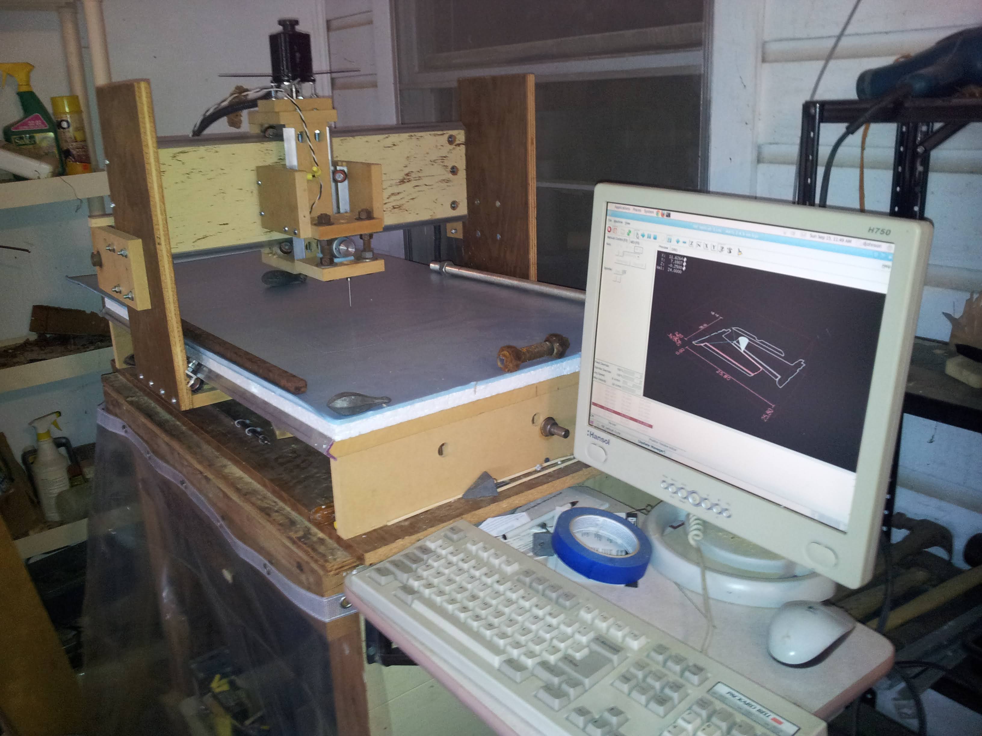
I did, however, start with LinuxCNC back in the 2010-2011 timeframe and I’ve thought it would be really neat to switch MPR&P over to LinuxCNC… just to come full-circle and make this thing all the more unique. Here’s LinuxCNC on Ubuntu controlling my BuildYourCNC-inspired needle-cutter machine back then…
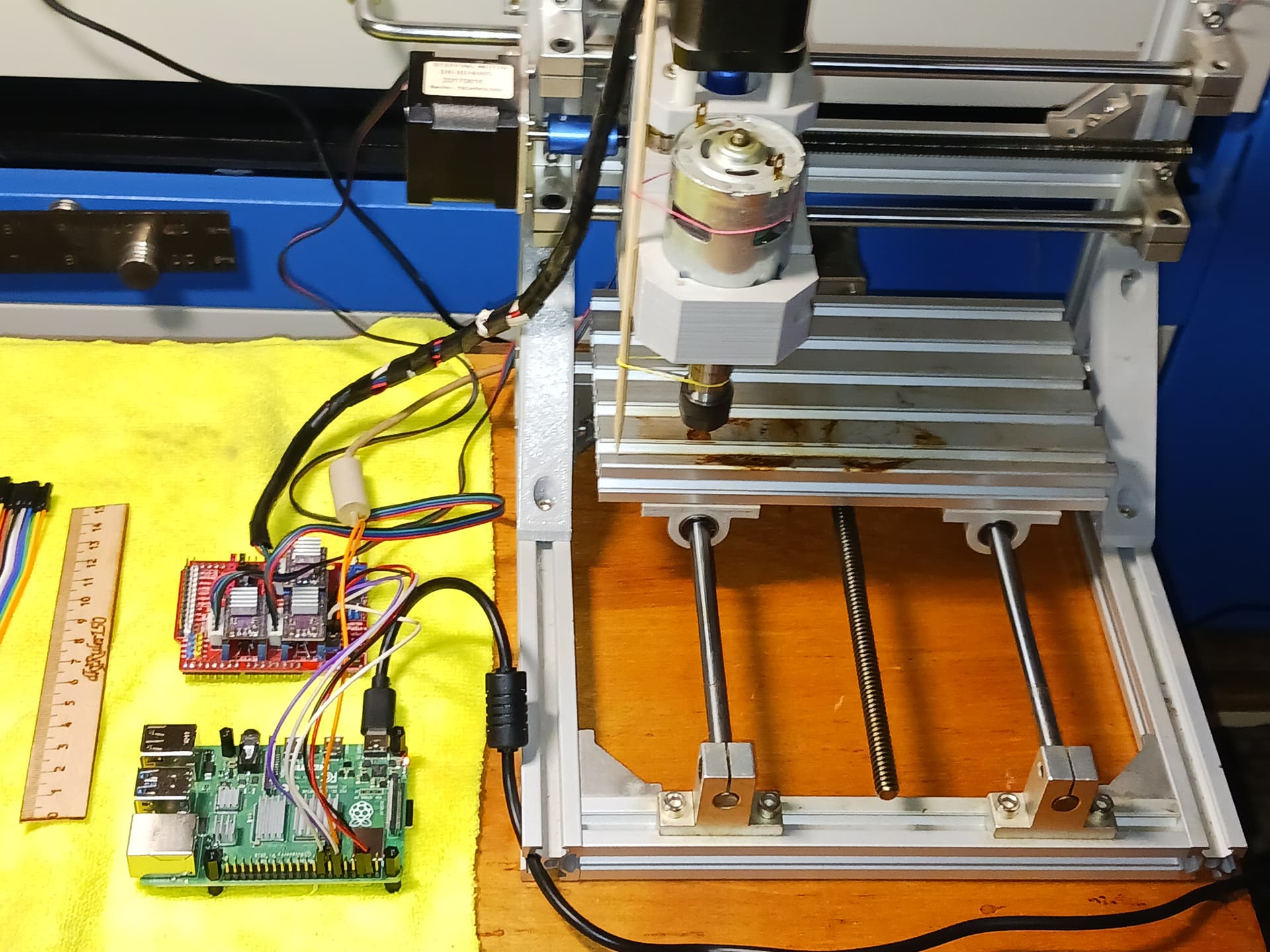
and now, gone is the desktop PC and its parallel port. My “inexpensive LinuxCNC interface” is a little two-board setup, with LinuxCNC now running on a RPi4, with a few GPIO pins connected to three or four DRV8825 drivers… and we have all we need to run our 3-axis machine.
But for now, I’ll leave it GRBL-based… and see if I can’t make it look more like a… [this was funny to me ![]() ]…
]…
Have fun!
– David
1 Like
Love it. I’ve recently been visiting a smaller makerspace close to my work instead of the huge one by my house. The small one has a ShopBot, which was converted to use LinuxCNC.
I’ll need to study this. As my collection of Pi 5 systems grows, I have a growing pile of Pi 4s that are looking for a new purpose.
Starting to fiddle with the parts in the slicer, getting the lay of the design.
While digging through my collection of old parts… Lookie what I found:
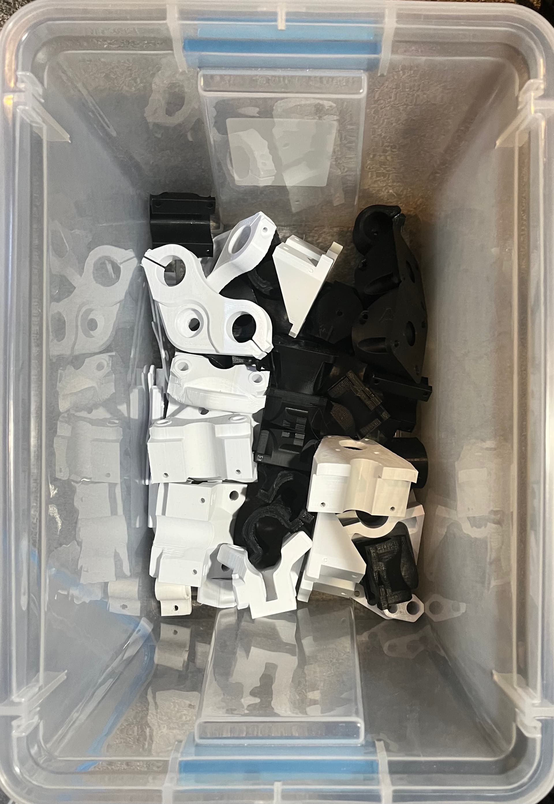
I think this is never-built V1 machine #2, (I have an original original set of MPCNC parts somewhere around in a random box).
1 Like
Oh, and I also have a twin to your 2018 machine… with the original controller but hasn’t seen use in years.
1 Like
I’ve kicked off prints as I start working a build this weekend.
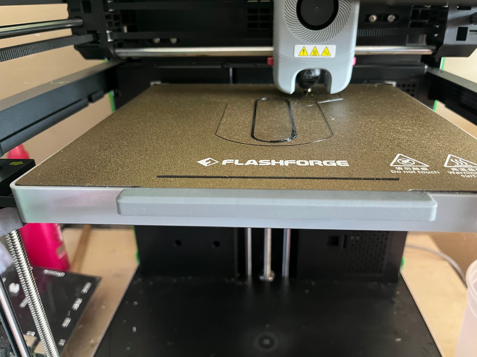
The 40 tooth rack fits diagonally on the FFCP and clones. One FFCP has a jammed extruder so I’ll work on that.
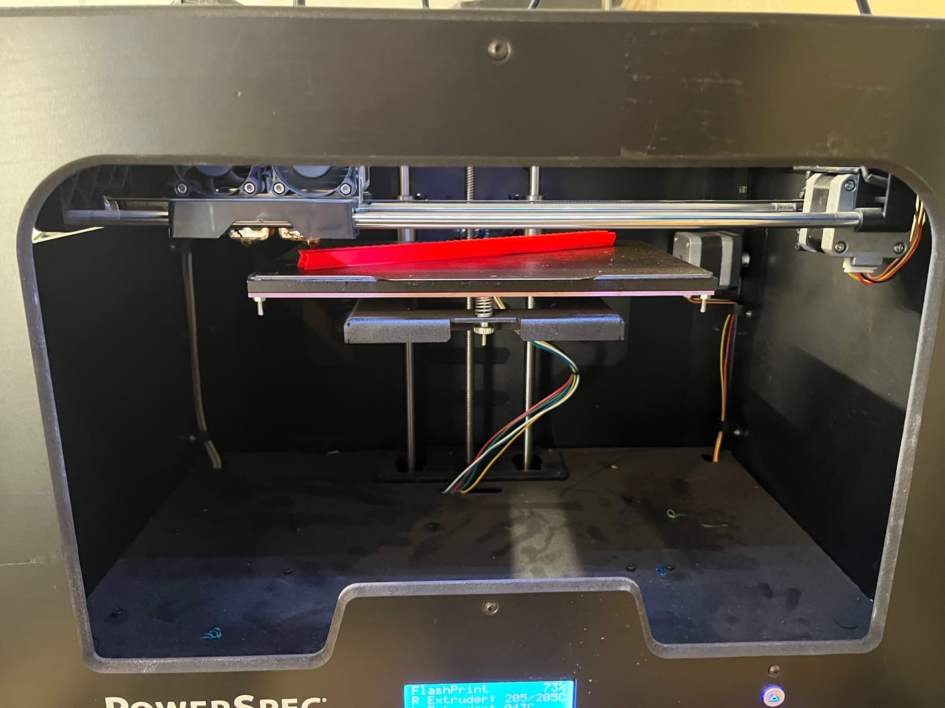
In the spirit of found materials, the red spools I"m using are left over from the beta program LR4 builds.
The A5M is getting the carriage supports.
Question about the carriage supports: It seems that it would be a good idea to put symmetric holes in these so the 1/4-20 rod can pass through the clips to the far side of the carriage supports. This lets you throw a washer / lock nut on them and the axis then might self-support while handlig it. I didn’t do this but I’m toying with the idea of it.
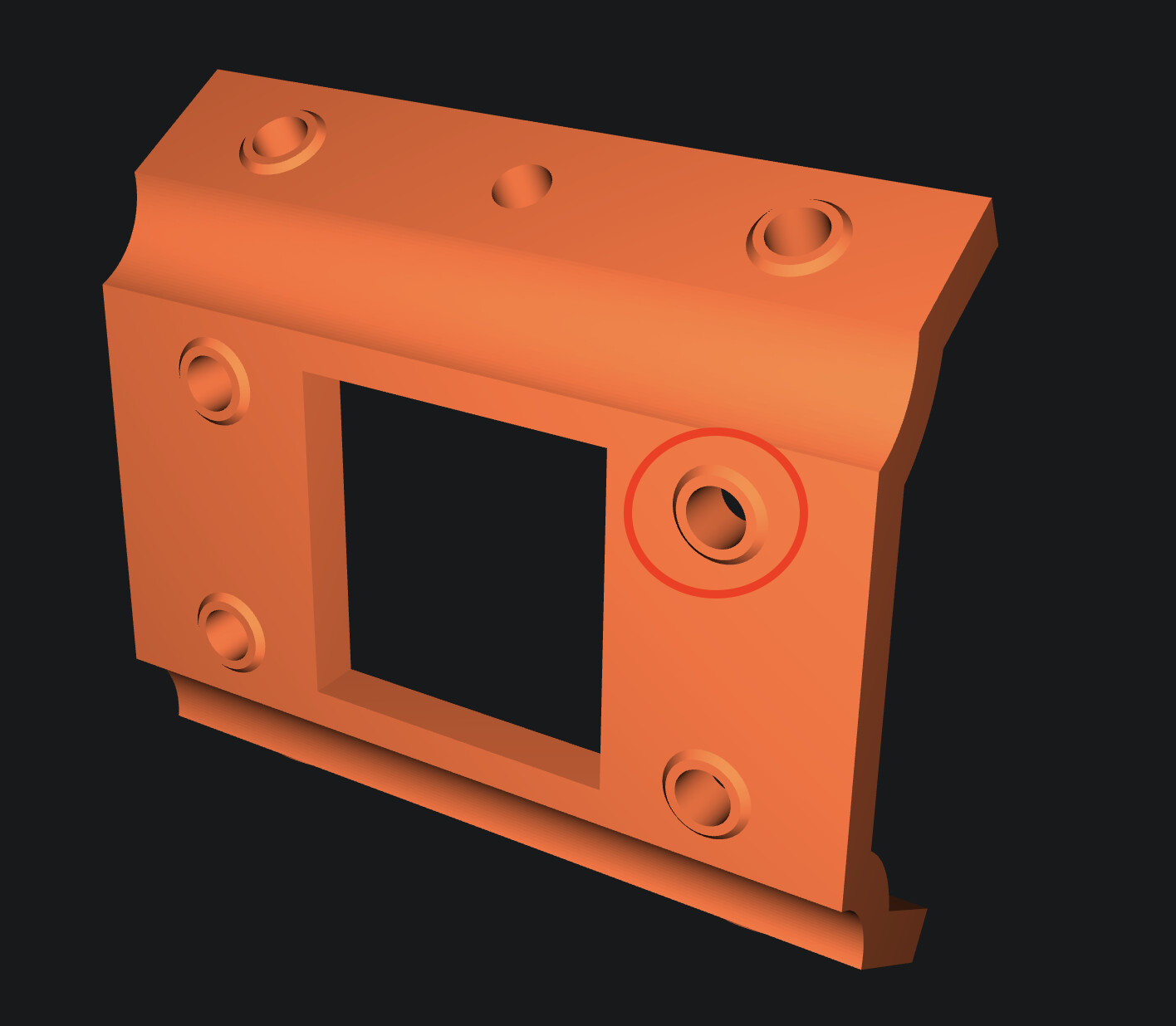
Next question: for the carriages, these spacers for the bearings appear to be the main reason I couldn’t print these lying down flat. (Some discussion of this already earlier in the thread). I’m toying with the idea of removing them and just printing equivalent small parts, and then placing the carriages with the large center portion flat on the build plate. What’s the drawback of doing that aside from needing to deal with the slightly aggressive overhangs?
Finally, have you played any more with anything Z axis related? Pen mounts etc?