Just think of the cost savings is we got rid of belts idlers and pulleys…More Mostly Printed. That first rack and pinion really caught my attention, but I wrote it off for a few reasons…but now we have the LR4, the MPCNC can be something a little different.
I have a PLA herringbone gear set on the main toolhead of my Taz 5 printer. It’s got tens of thousands of hours on it extruding and retracting, and it’s still going strong. Not to say wear isn’t a thing- but I’ve been really impressed how well PLA has held up in that application. The gear set has outlived probably 5 hobbed bolts.
There were similar herringbone gear sets on the extruders of the mini farm of Lulzbot AO-series printers that the local makerspace had back around 2015, which were donated by Lulzbot when they upgraded their print farm from AO series to Taz series printers. Each of the roughly dozen of those had tens of thousands of hours on them, and they were also in remarkably good shape.
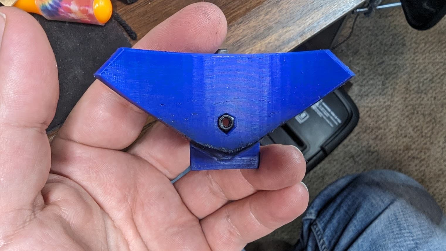
That’s after knitting around 2 dozen pairs of socks and probably close to the same amount of yarn knit learning how to use it. If you look you can see what the original shape was like and how much has worn down.
This is a very high wear part - it’s PLA and for each row on a sock it presses down 64 metal needles that are under considerably tension from the yarn hanging on them. It’s probably the highest wear 3D print I’ve dealt with. I’ve done quite a few things with gears including a few extruders but none stayed in service super long, and many like clock gears (both motor and weight driven) just don’t see much force on them so have very little wear.
When it reached this point and I decided to replace it I had the sudden realization that some of the Chinese PCB shops now offer 3D printing in a wide range of materials at low prices. So I had the replacement made with 3 alternative 3D printed processes:
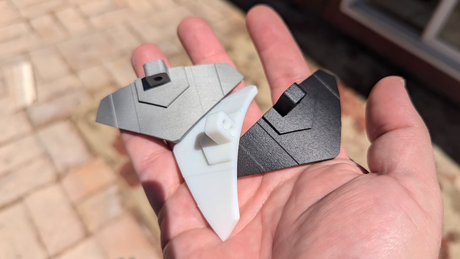
The silver one is sintered stainless steel - it cost about $16 - weights 67g and with a bit of work actually polishes up really well (I’ve only polished a tiny spot to test so far.) The black one is a MFJ Nylon that only weights 8g only cost $4 and should be very tough. The white one is a SLA 9600 Resin print. It cost a whopping $0.60 and weights the same 10g that my PLA part did.
I tried the metal one and it works great - but the raw surface is a bit too rough and makes the machine a little harder to crank and a lot louder. I’m worried about the slightly rough surface wearing down the needles more than I am about the needles wearing down the cam. I need to do some polishing on the edges that do the work before I put it back in.
I decided to try the white resin part next since it’s the one I had the lowest expectations from. I’ve only done about a half dozen socks with it in the machine so far but there’s basically no sign of wear yet. The commercial resin they used is much tougher than any of the resins I’ve tried in my own MSLA printer. My own experiences with MSLA have been pretty frustrating…it’s smelly, messy, and while it does great looking highly detailed parts - holding tolerances is almost impossible for a variety of reasons.
Now for big parts the costs go up quickly - I got quotes on having some of the larger parts of my sock knitting machine printed in these processes and it quickly got into the hundreds of dollars. But for some sections of rack like this the costs are probably pretty low.
So…I’m not a huge fan of something I’d have to have made for me, I always prefer being able to make my own parts like I assume most here do. But it is worth considering since any of these 3 processes create parts that are just as dimensionally accurate as FDM printing if not more…and they’re all also more heat resistant and so far seem to be more wear resistant in a very high wear situation. And there’s no reason why someone couldn’t start with FDM printed gears and then deal with commercially made gears from a commercial process if they find they need more longevity.
Just “blue-skying” it… thinking out loud. Please be kind. I don’t know what I’m talking about…
Are there metal parts fabrication outfits out there similar to the PCB fabs that have become so popular?
I’ve used only one unique ~8" (~200mm) rack segment in this entire machine: three rack segments across the X-axis, two each on each side of the Y-axis, and one segment on the Z-axis… for a total of 8 segments for this machine. But 10 segments would give a machine with a working area of 480mm plus in both X and Y.
IF a proper gear ratio is found to provide the combination of speed and power for a new MPCNC… and R&P should become the next “big thing” in the MPCNC world… could a single standard rack and gear set be fabricated in sufficient quantities to make it a “reasonably priced” component for a machine such as this?
The cheap alternative is to print the R&P parts as I’ve done here. That might suffice for many, if not most, folks CNC needs… especially if sporadic. But it would be interesting to have some folks (Ryan?) playing around with the printed R&P gear ratios and determining how long before wear becomes a problem…
PCBWAY would make you a sintered metal or nylon part. Pretty reasonably I believe though I’ve never done it. If you upload an stl I think you can get a quote to see.
I didn’t design it - just made it from existing designs.
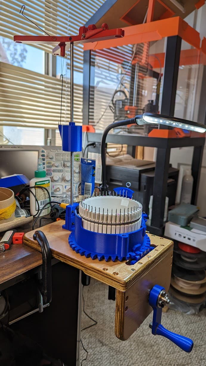
It started as this machine:
But just after I built it someone took that design and did some improvements to make it easier to build and released them here:
And I’ve upgraded it with a number of remixed parts from this guy:
I originally used a 3D printed base for it - but found it flexed more than I was comfortable with - so I used the 3D printed base to make some 3D printed templates I used with my router to make a wooden base…of course if you have a MPCNC you could just cut them that way
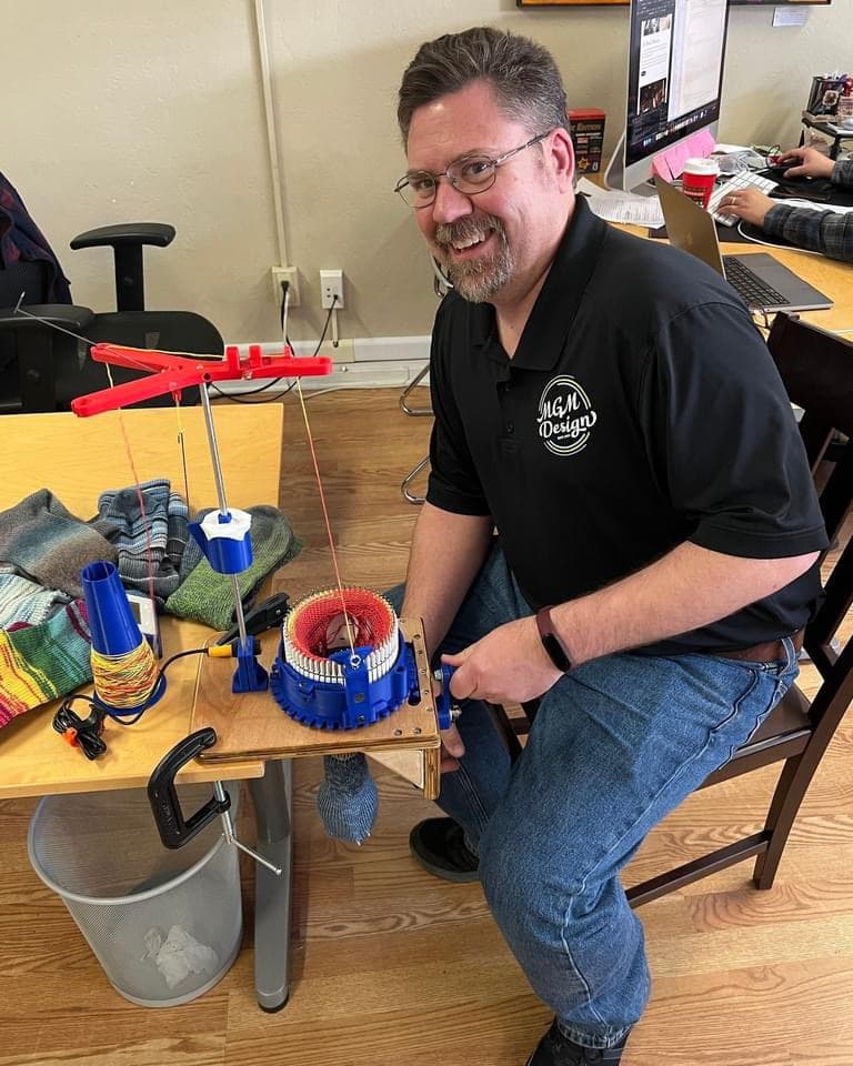
I made it just out of curiosity…I’d always found knitting machines interesting from a mechanical point of view. Then a few years ago youtube suggested a video from someone who designed a printed machine because he wanted to understand how they worked better. His was more like the addi/sentro hat machines and he didn’t get it working very well. But it piqued my interest and got me doing some googling. Now I only wear homemade socks and will gladly talk peoples ears off about how great they are
I half joke that it’s because I adopted a border collie from the local pound and he somehow pushed me towards it. Once I made the initial machine I soon found I was buying nice wool yarn every chance I could…which led to me getting a little spinning wheel and learning how to spin my own yarn (which I’m still terrible at and have yet to make any usable yarn) and my family is pretty convinced that now I’m going to wind up with some sheep because of how I tend to take things a little too far
Back to the original topic - yes and so does JLCPCB which is the service I used. No commitment…just upload the part and select a process to get a price. Honestly even though metal was the most expensive process by far it was still quite a bit cheaper than I expected it to be. Though I think 9600 resin or MFJ Nylon would make quieter smoother gears that would hold up fine for a fraction of the cost of metal.
i know pps cf isnt really something that everyone can print, I feel like its stiffnes might be the key. I also had briefly thought of derlin which has shown to wear extremely well in bushing applications.
Exactly what I was thinking. Those things last forever and take a beating.
I mean they can be injection molded for fractions of a penny but really I think the key here is 3D printable. For people with a printer it would be even less expensive. I am really not concerned about the wear. Lube would 10X the lifespan if needed. Slop is the main concern but it can be mitigated a few ways.
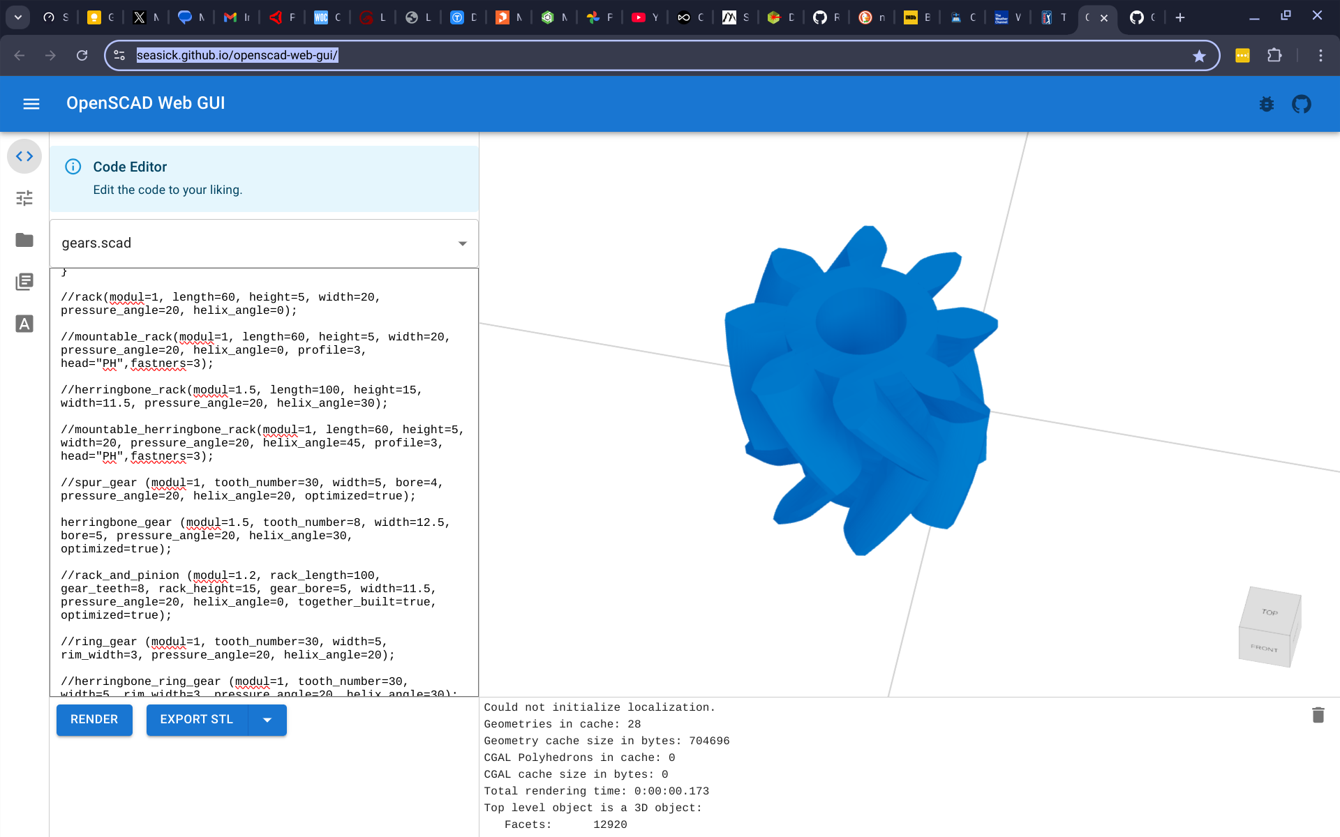
Played around most of the day with OpenSCAD and herringbone gears. I found an online version of OpenSCAD that my Chromebook happily plays inside the browser… and now I don’t have to drag in another laptop.
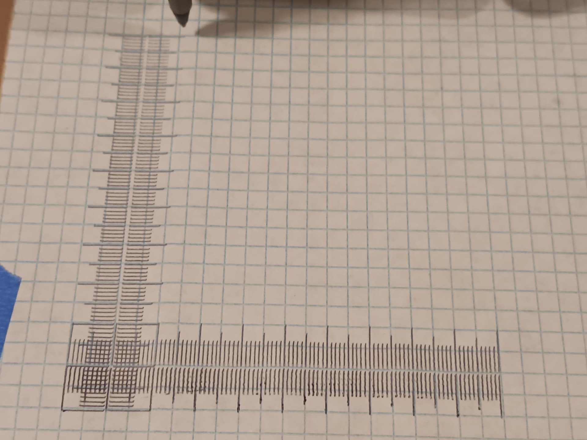
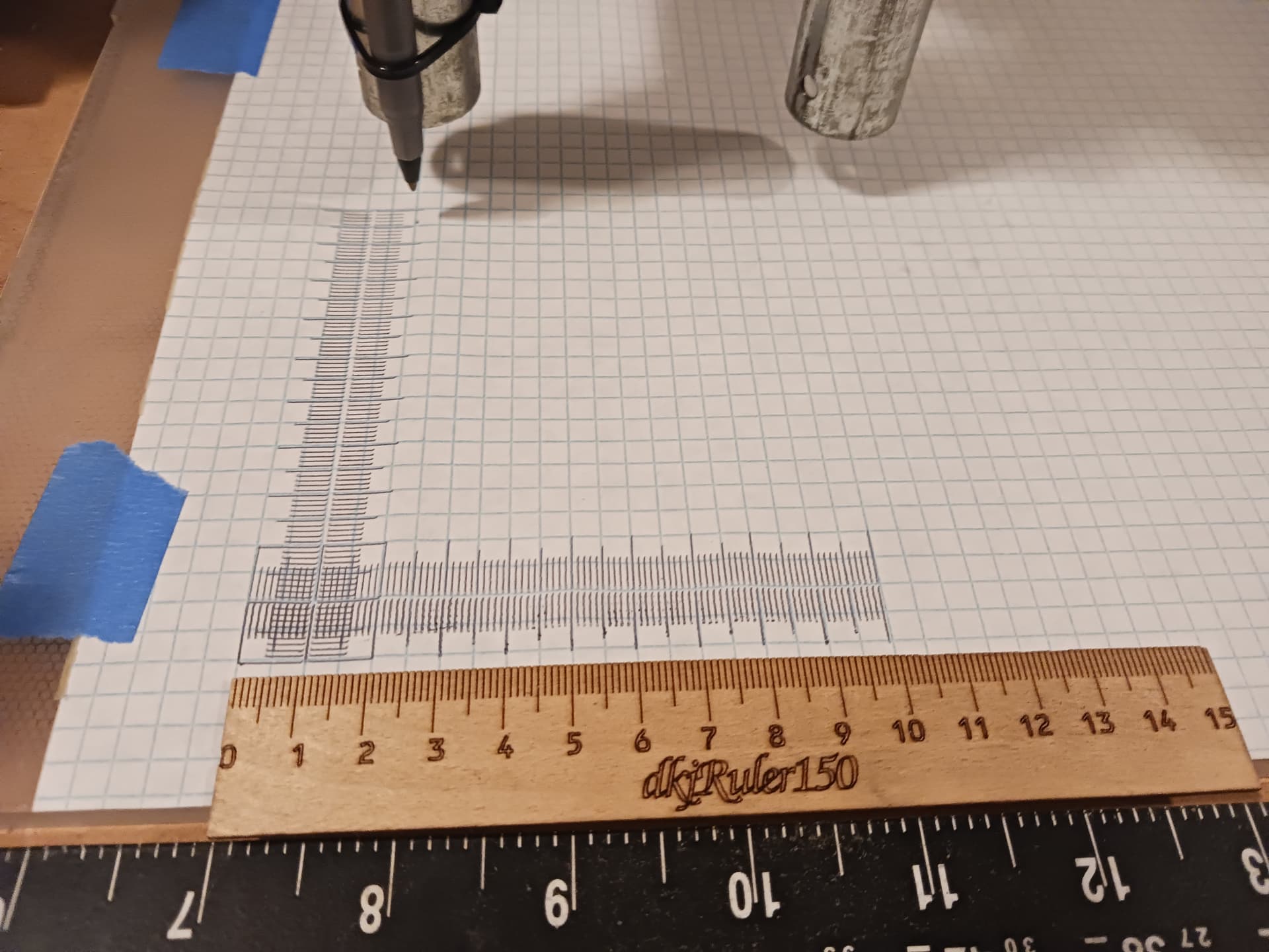
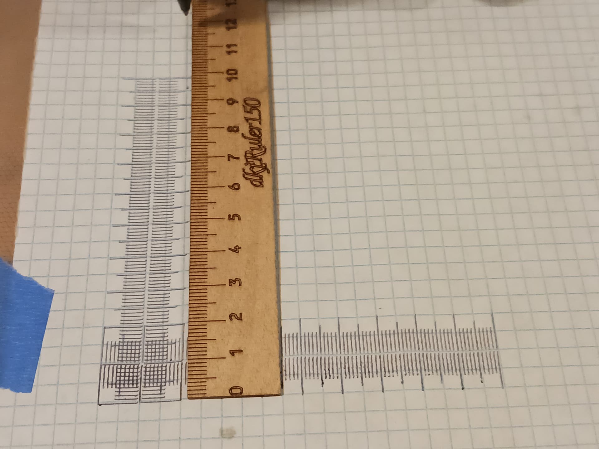
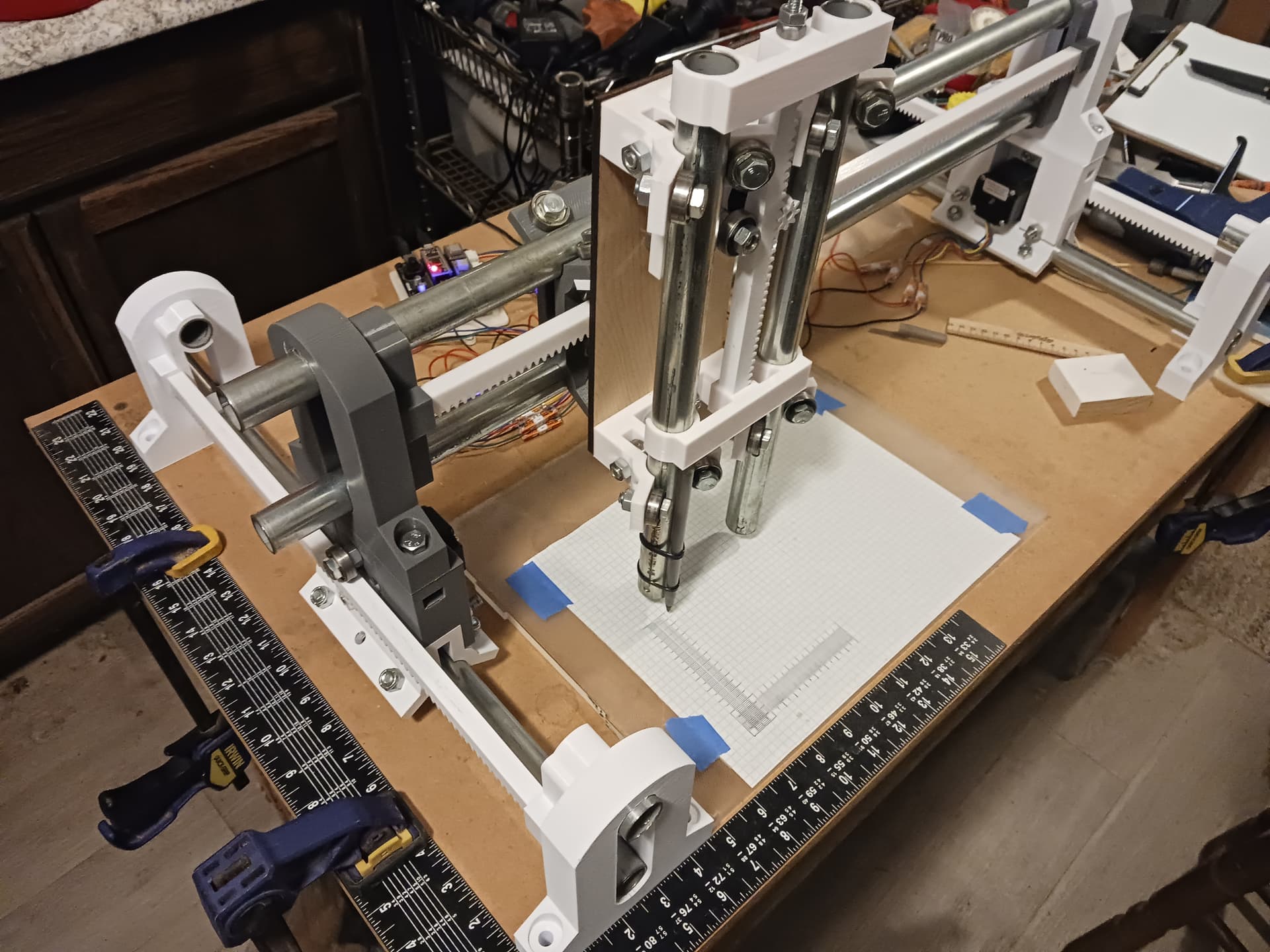
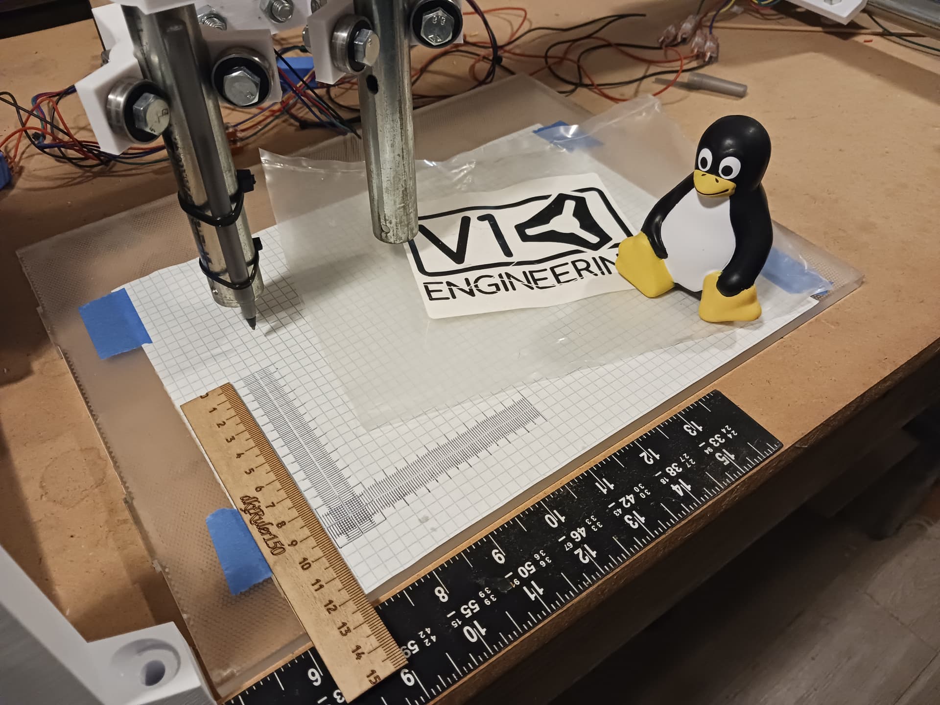
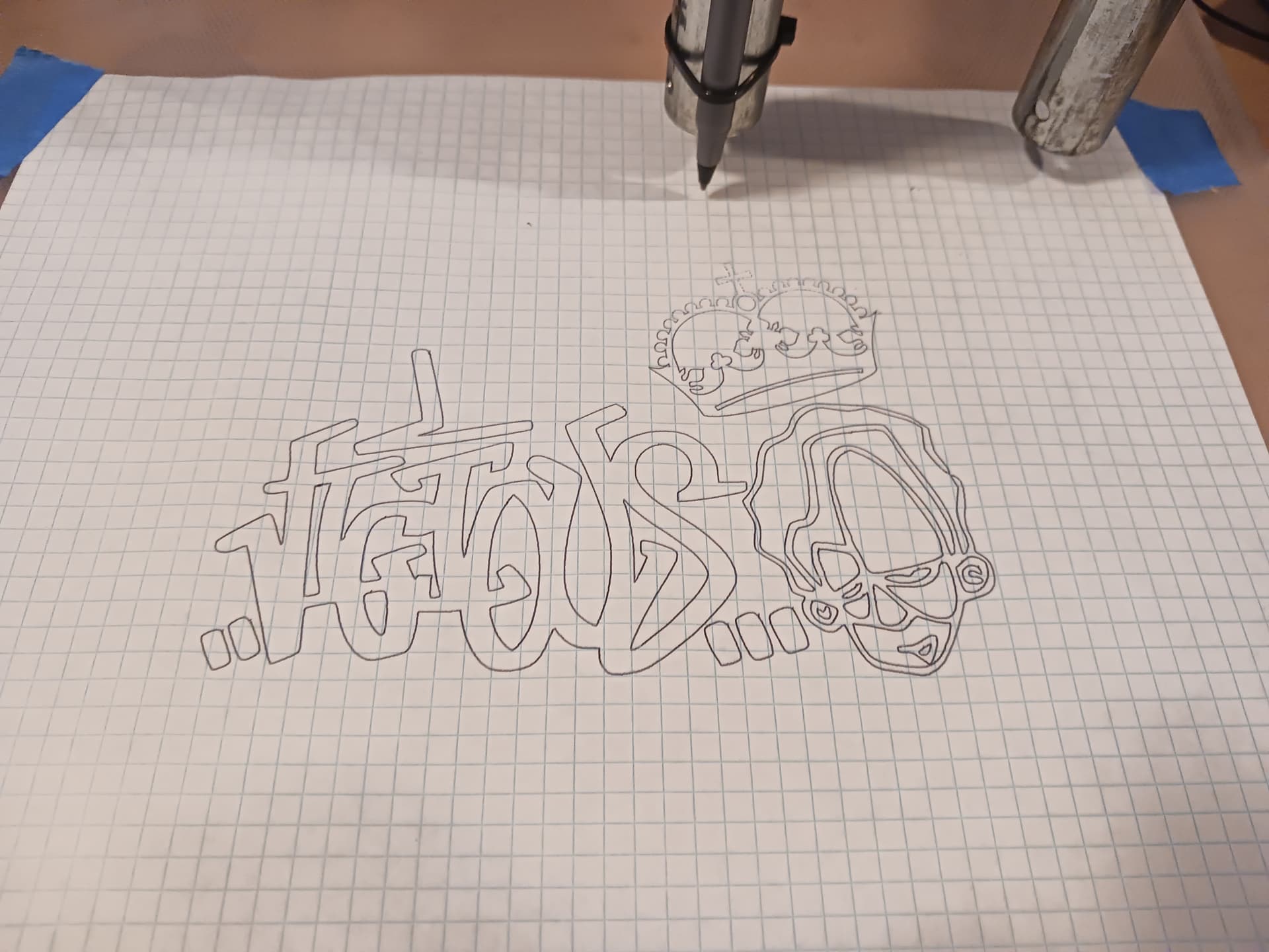
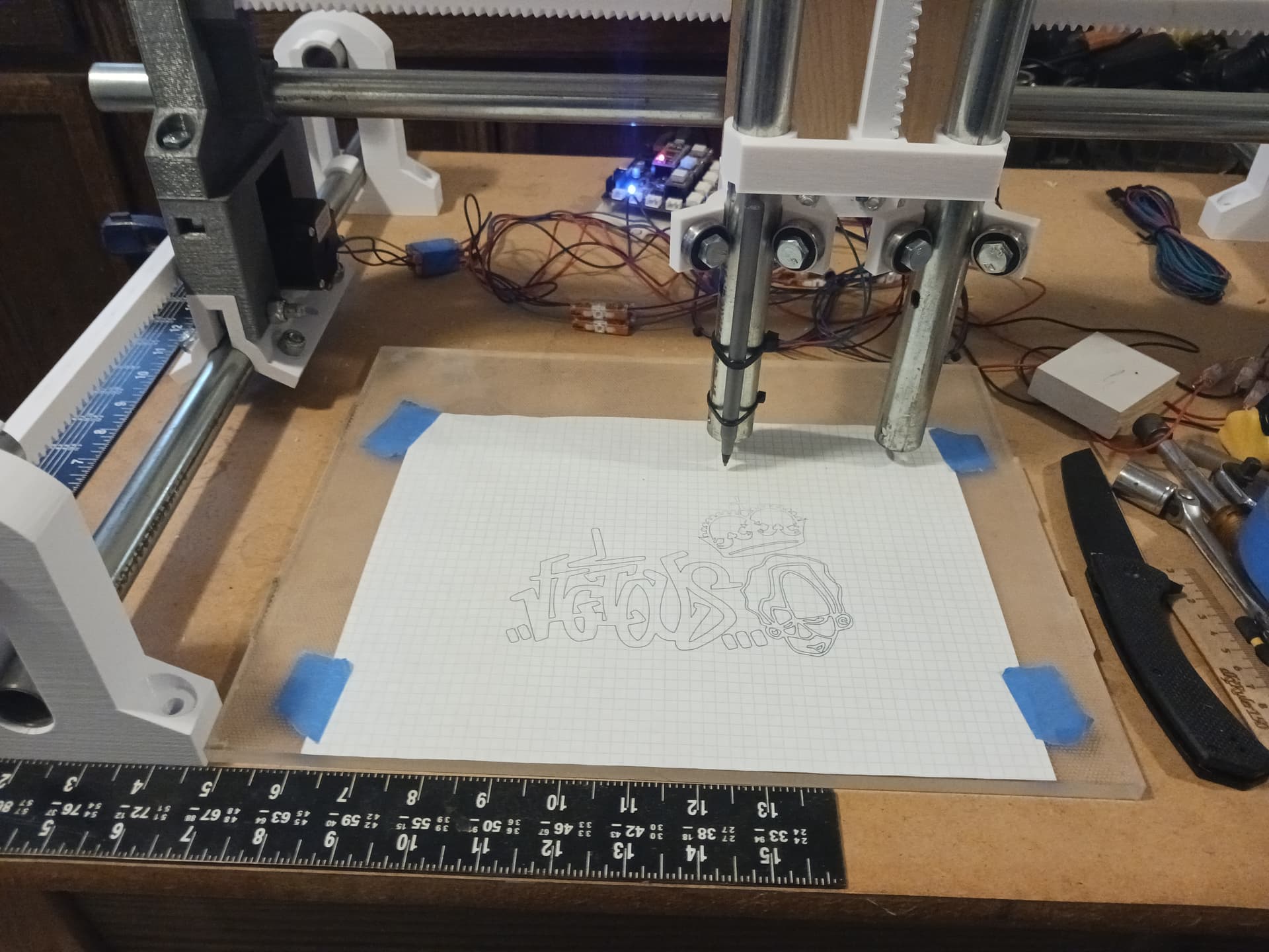
Finally dawned on me that with my new Z-axis I still needed to plot some rulers from Jamie’s Test Pattern Generator…
so here it is… plotting underway already but you get the idea.
His ruler generator actually generates gcode for two rulers in each axis… one drawn fully in one direction and the other in the opposite direction. Various maladies can be spotted with this approach… backlash, improper/irregular spacing, etc.
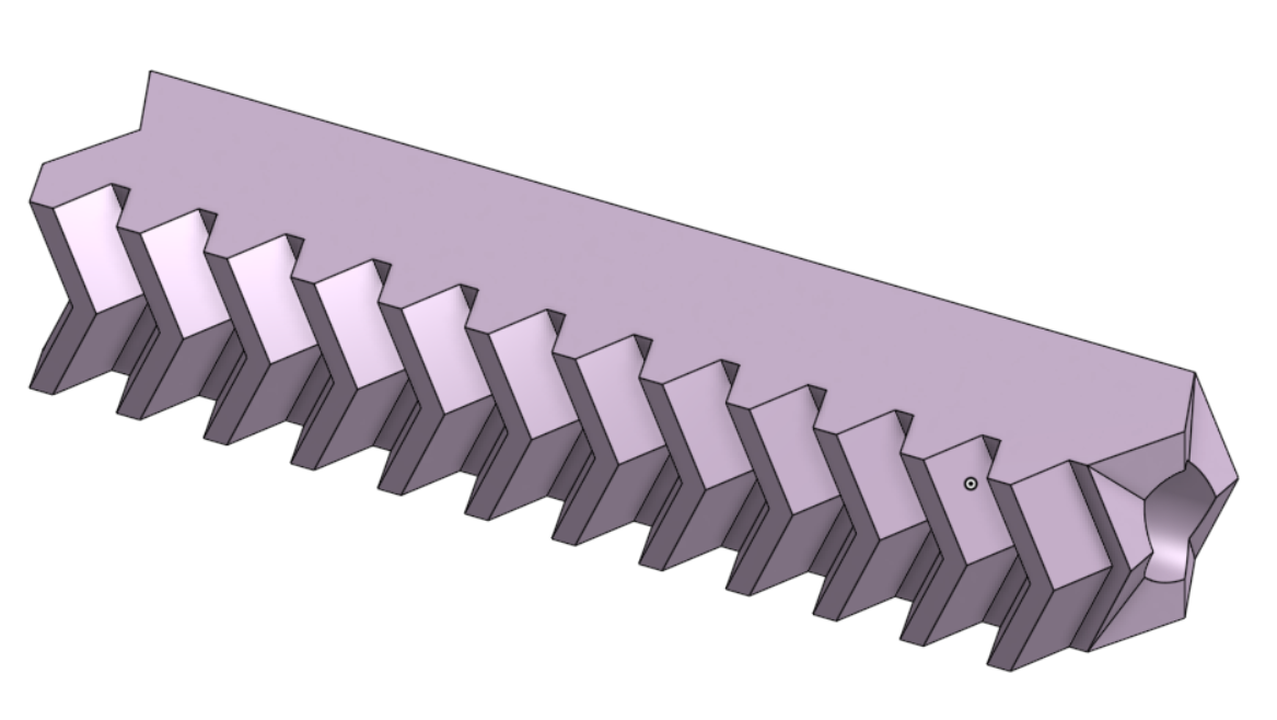
For those interested in playing around with R&P and other gears…
This online OpenSCAD and this “gears.scad” file allow for making quick and easy R&P STL’s to play with. At the end of the file, there are numerous gear examples that simply need to be uncommented to edit parameters, and then render and export.
I usually import the STL into FreeCAD first and convert it to a STEP solid model that I can import into Onshape and make into a useable part; i.e. add the 1/4" hole through the rack, clean the ends of partial teeth, make mating surfaces, etc.
On a personal note… I often forget stuff I use only sporadically, so I’ve started asking Gemini how to do stuff. Rather shockingly, I asked, “How do I create a STEP model of an STL imported into FreeCAD?” and got a quick response, that included the following extremely helpful and accurate information…
FreeCAD Workflow
Here’s a general outline of the steps involved:
Import the STL:
Open FreeCAD.
Go to “File” > “Open” and select your STL file.
Mesh to Shape:
Switch to the “Part” workbench.
Select the imported mesh.
Go to “Part” > “Create shape from mesh.”
Adjust the “tolerance” setting as needed. A lower tolerance generally results in a more accurate shape but can also increase processing time.
Refine Shape (Optional):
Select the newly created shape.
Go to “Part” > “Refine shape.” This can help smooth out some of the triangulated surfaces.
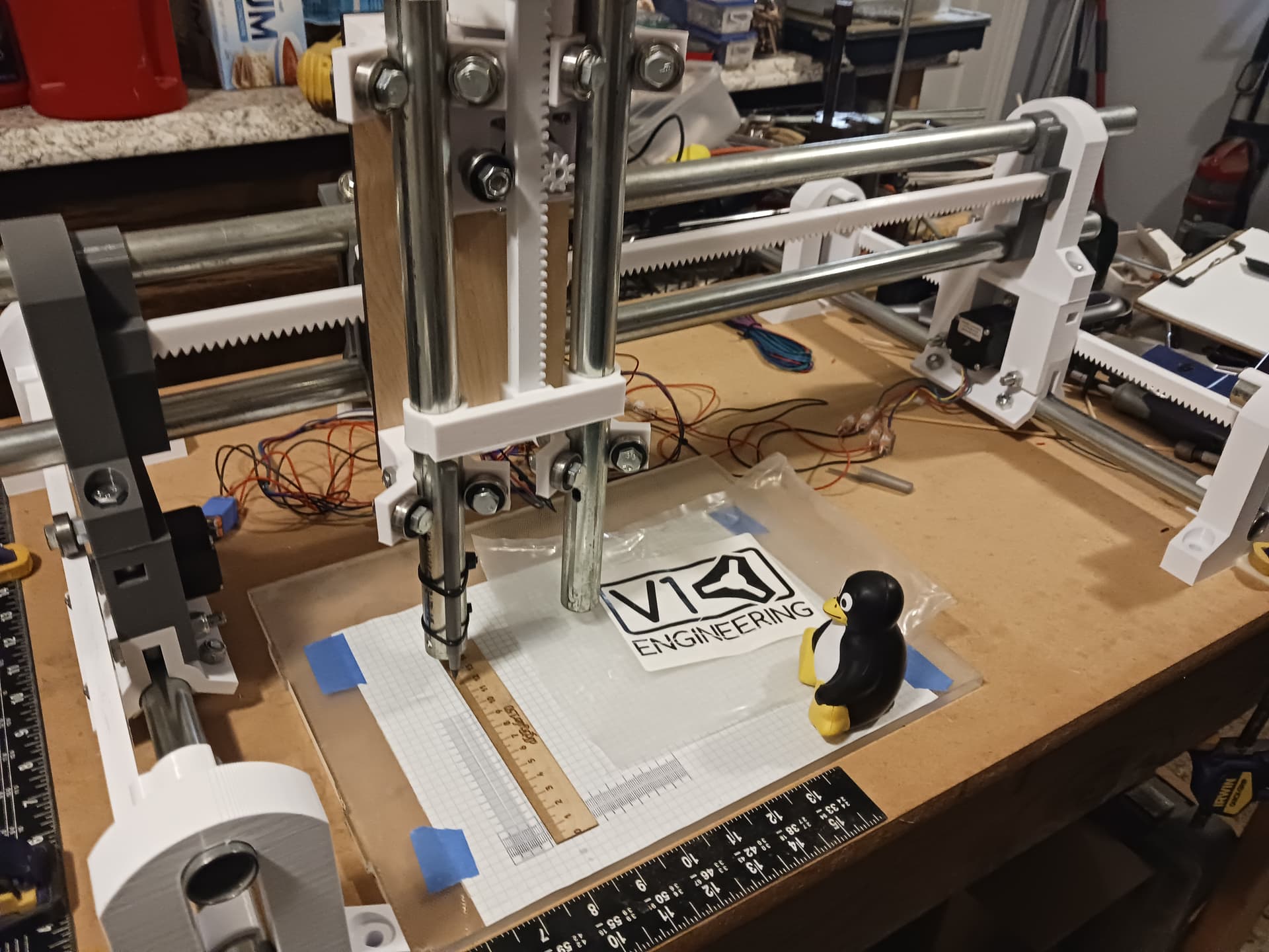
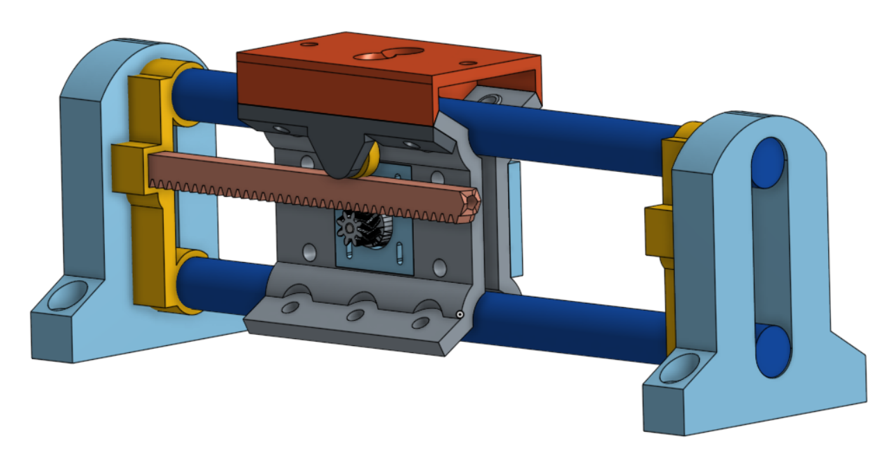
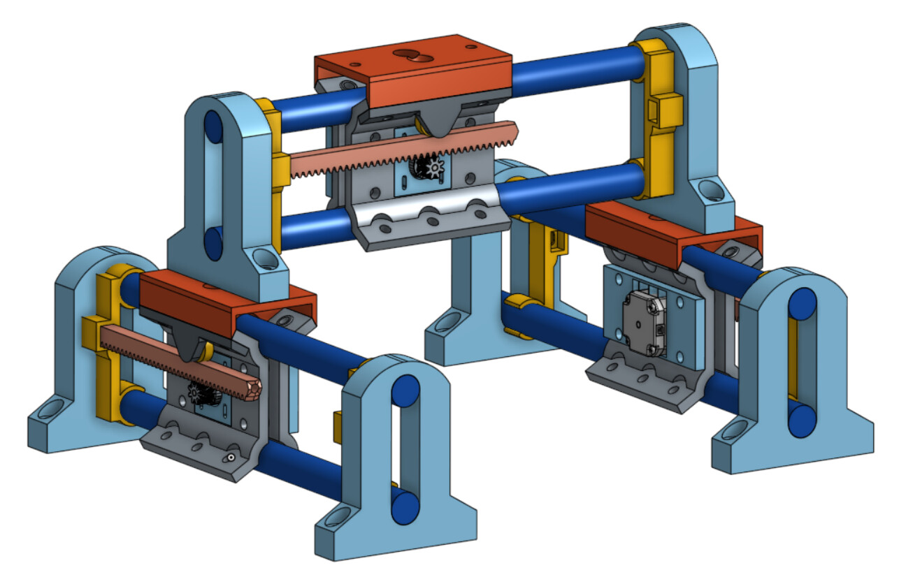
The more I’ve looked at this machine, the more convinced I’ve become that it could be simplified even more. There’s no reason that the gantry and Y-axis rail and carriage assemblies couldn’t be identical – at least on paper… I’m printing parts right now to fit-check and test.
This would be three identical 2-rail assemblies that are essentially the same as the gantry on the machine I’ve been playing with. It becomes a little taller but it also addresses the concerns that Jim and Ryan raised about the possible lack of rigidity in the 1-rail Y-assemblies on the current machine… two rails have got to be better than one, right?
All that remains is to adapt the current Z-axis to the red gantry adapter plate and it should be ready to test. I’ll replace the gantry with the updated parts I’m already printing and then print the same parts again (provided fit-checks are okay) for the two Y-axis rail assemblies. Maybe the Z-axis could be made near-identical as well… just remove the slotted end supports and replace the bottom end with a tool holder?
The self-standing machine as it is now is still devoid of small parts… the four 3mm motor mounting screws on the 4 steppers are the only exception. Otherwise it uses only an assortment of 5/16" (8mm) bolts and the 1/4" (6.35mm) threaded rod for the racks. It will, of course, need to be “stiffened up” to carry more than the pen or laser that it does now… but I’ll leave that as an “exercise for the reader”.
That’s interesting. That would make it pretty easy from a build standpoint to do things like dual gantry and/or dual core. It’s almost like building with Legos.
All kinds of interesting possibilites. Multiple cores. Even cookie cutter setups where you have multiple identical modules. Run one job at the same time on 2 or 3 or 4 modules at the same time.