Hey, I am not a cop! ![]()
1 Like
RepRack
1 Like
The greatest Rack… -_-
1 Like
I’m know I’m indeed fortunate. I know what it’s like when you still must work for a living and/or raise and support a family. Your time is not your own… you must share it with others. But that is all behind me now for the most part… I’m old, retired, live alone with my dog, and am considered “unreliable” so pretty much all my time is my own now. I’m relatively healthy yet and still able to be somewhat independent… but thankfully have a daughter and her family nearby, just in case.
I also love doing this stuff… and always have! So working from a well-stocked junkbox and being able to design and print any parts I need… I don’t spend time waiting for orders to arrive, waiting on somebody to advise/respond to me, or have to go to bed earlier than I’d like in order to be someplace in the morning. I spend a lot of time in Onshape, keep the 3d printer going night and day as much as possible, rummage through my junk to find parts… and that leaves only the fitting, assembly, and testing to get where I am now. Lots of the work can be done in parallel.
This has been a fun project. I’m even losing weight (which I needed to…) without trying… I hate stopping to fix something to eat when I’m on a roll.
![]()
2 Likes
Perfect for this application. You’re welcome.
MPR&P Sounds good to me.
Love it when serendipity makes an apperance.
Get that Z put together, and slap some tools on it.
Can’t wait to see some ruler tests or cool box / laser work.
You’re cruising right along.
1 Like
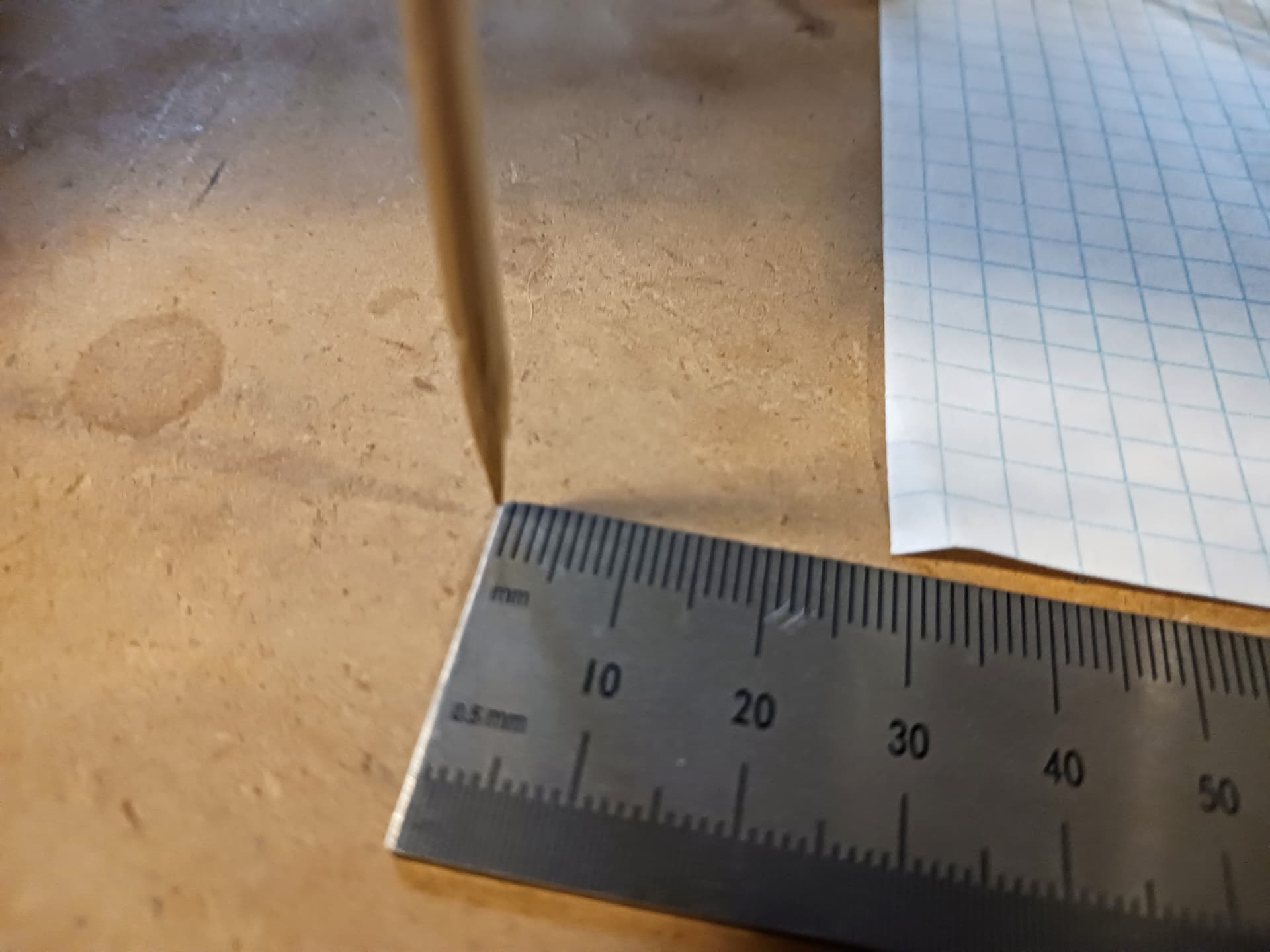
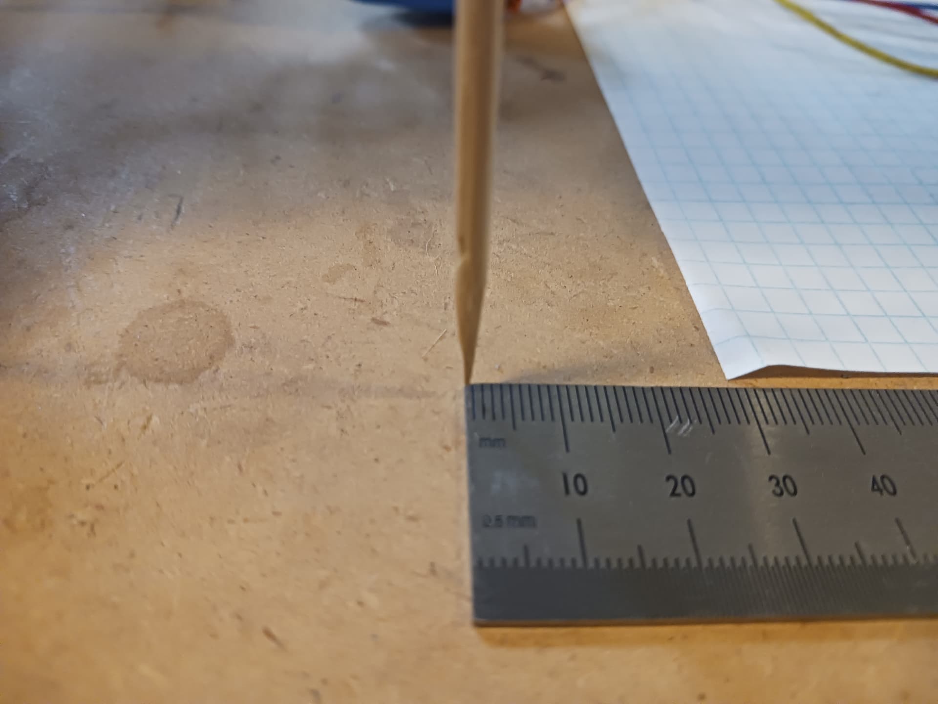
I did an initial calibration of the X-axis on this MPR&P (it’s growing on me…) machine. The Grbl 1.1h previously flashed into the Arduino Nano had 160 steps/mm for both $100 (X) and $101 (Y) settings. So using my “skewer method”…
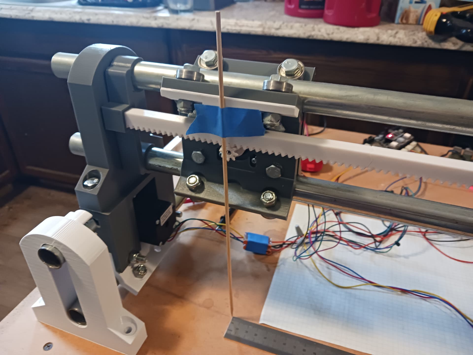
I eyeballed the tip close to a metal ruler’s “0” and commanded a 300mm move… and it moved consistently to 314mm on the metal ruler. And using [(commanded/actual)*current_$100] I computed a new steps/mm setting of 152.8. Setting $100=152.8 and commanding the same 300mm move yielded…
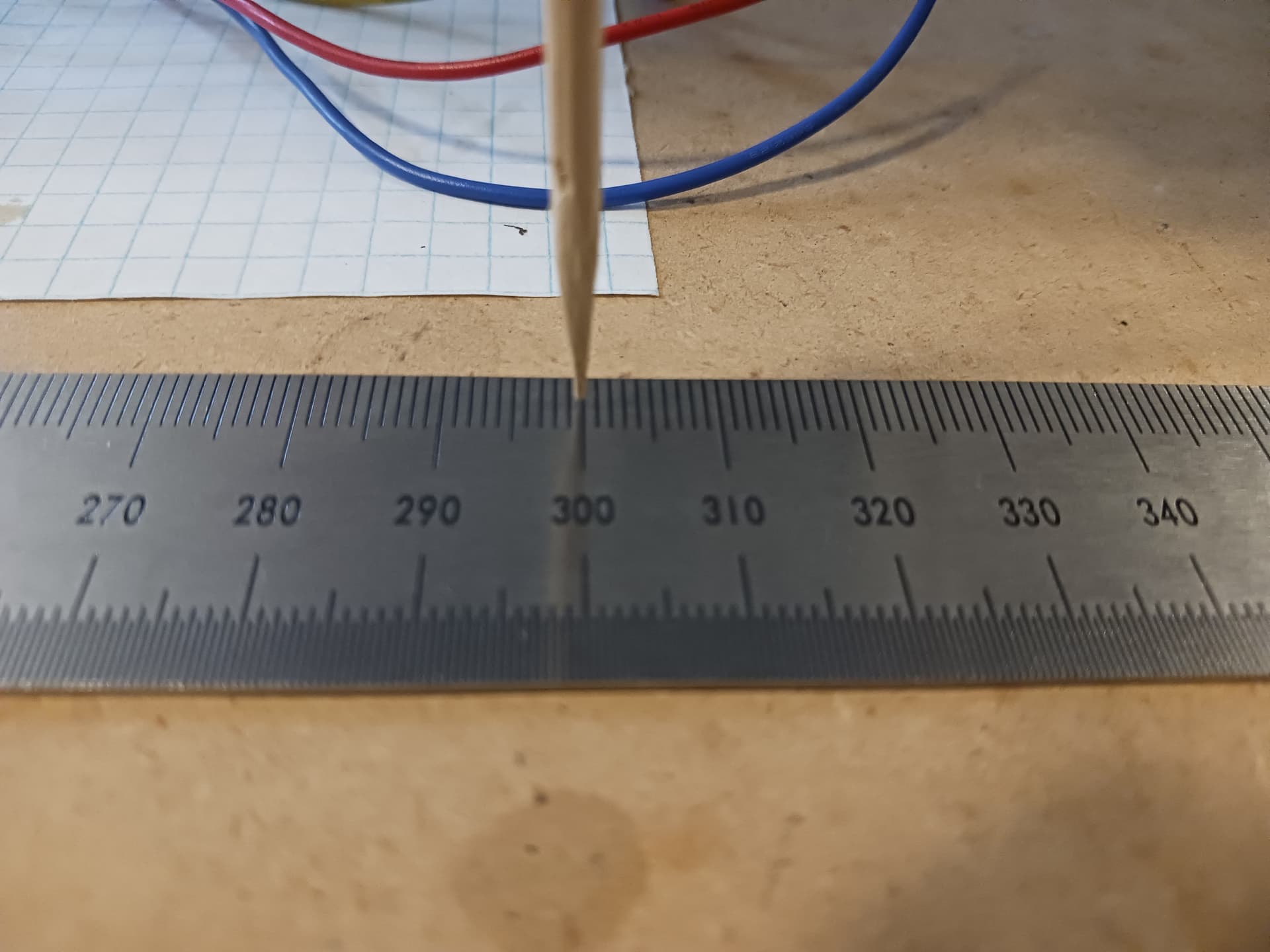
which is certainly close enough for now. Since both the X and Y axis use the same rack and pinion setup, I set the Y steps/mm setting ($101) to the same 152.8 value… and trust it should be reasonably accurate as well. I test it for sure later.
I then ran a laser gcode file that was handy… and air-milled it. It’s doing a series of hex figures in a grill pattern… 4 times around each hex figure. Sorry about the shaky video…

The Z-axis design is gonna be slow going, I’m afraid… I tossed and turned all night thinking about it. I may try to temporarily strap a laser on the carriage just to see what it can do.
Later.
3 Likes
Finally! Some progress today…
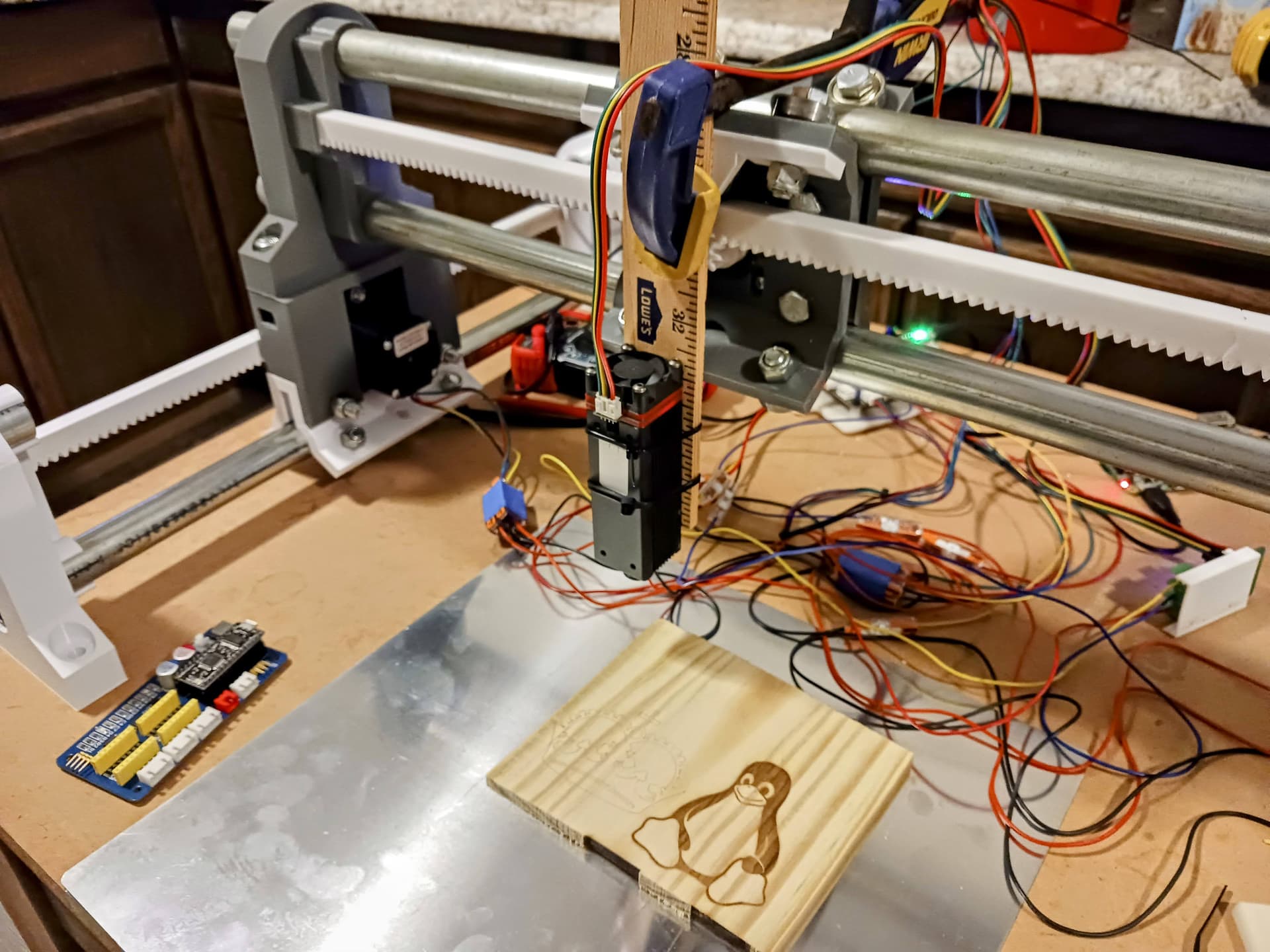
Between spinning my wheels all day, trying to come up with a R&P Z-axis design and fighting a balky Nano, I finally made a pretty decent first attempt to laser something…

with this crude setup…
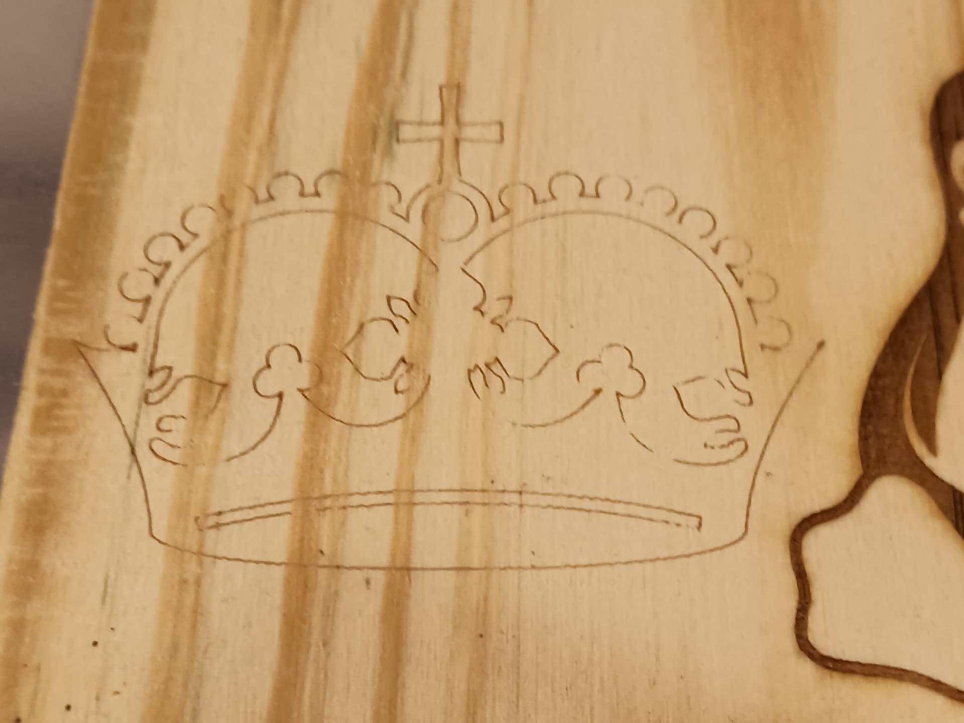
The video is actually the second crown I did… didn’t get the camera set up in time to catch the first. The first was accompanied by a welcome guest (a raster) that took about 15 minutes longer to laser than the crown. Here’s what the first run resulted in…

The crown was a vector image that took only a minute or so… and coulda used “more powa…” but that area of the wood was pretty inconsistent as well…
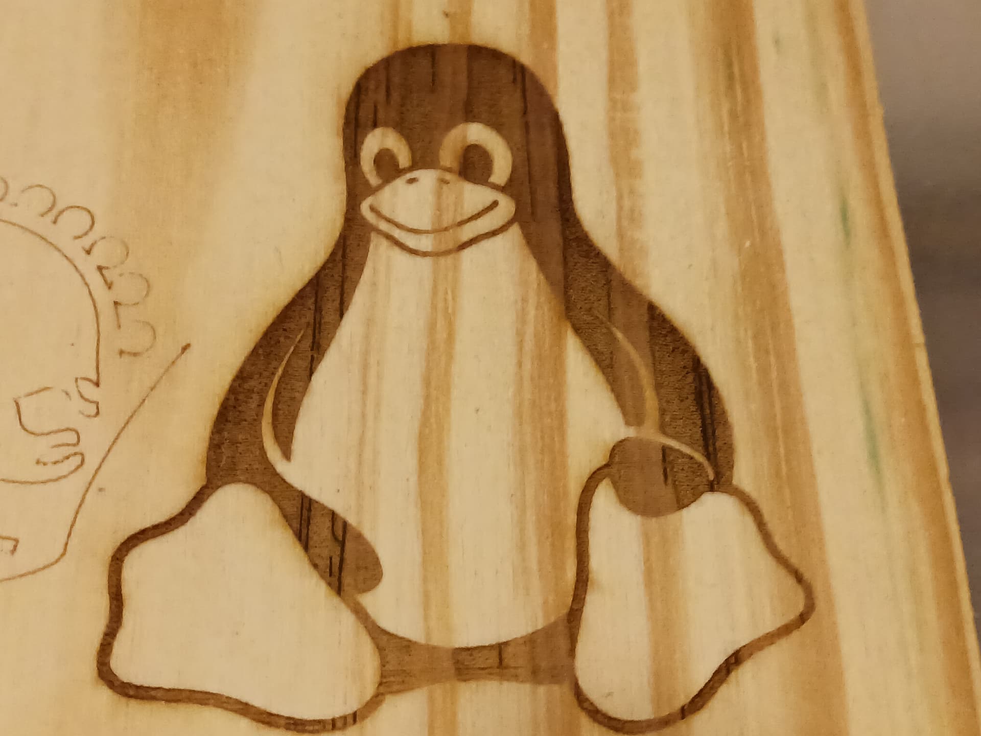
Tux was a raster image and came out much better…
The “balky laser” wouldn’t fire though everything else worked fine… and I dug around in my junkbox and finally came up with another Nano, already flashed with Grbl 1.1h to replace the Nano I had been using. Shock of shocks! Viola!
It made my day! Gonna take my time now with the Z-axis. Always helps to finish my day on a high/relaxed note; i.e. JD… or a silly crown!
![]()
– David
9 Likes
within at least a quarter of a mm over 300 isn’t too bad for a first attempt!
Proto Z!
Great progress again. Still cruising through the spare parts bin and workbench work holding parts to make a usable machine. Looks fun and rewarding to me.
2 Likes
I refined the calibration of my X-axis by repeating the skewer method tests of yesterday. This time, however, I checked it over 450mm (rather than 300mm) and calculated a new steps/mm setting ($100) of 152.88 vs. the old 152.80. I set the new value and rechecked… looked good. I decided it was now time to engrave a ruler on craft stick…

Sadly, I only guessed at the settings for engraving and cutting a craft stick with the low-powered Neje laser I pulled out of my junkbox and it failed to cut out, even with 4 passes…
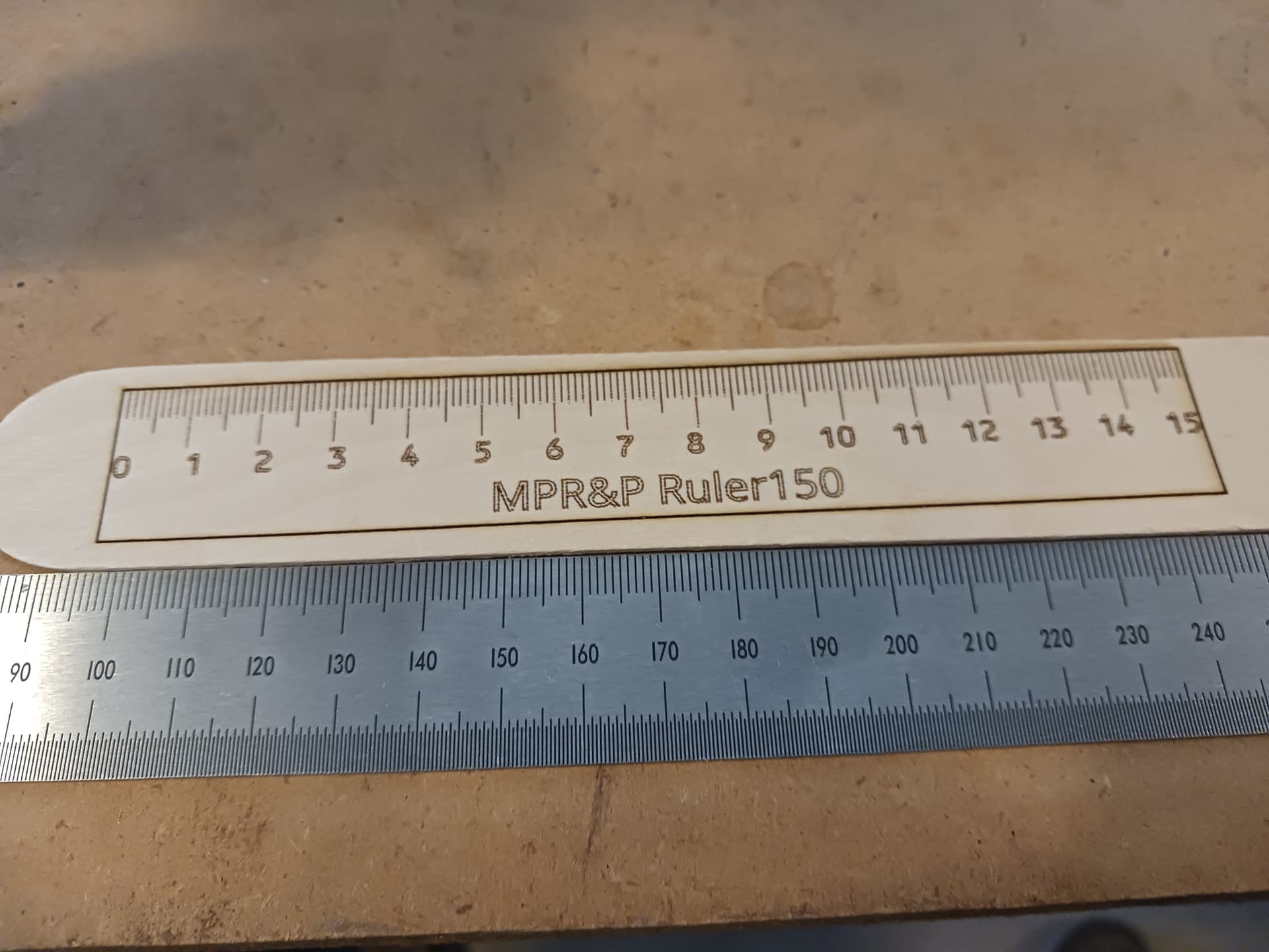
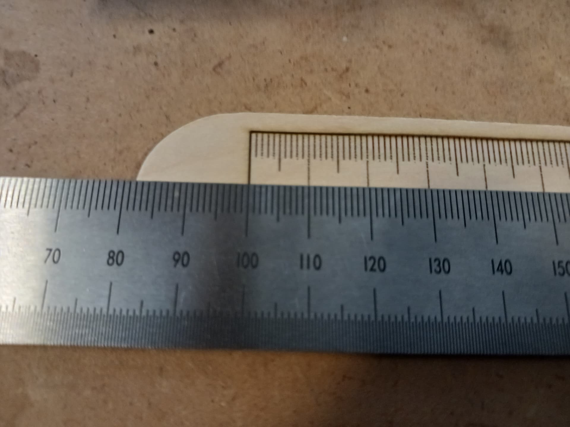
Ignore the parallax and focus on the center of the image to see reasonably decent alignment of the millimeter markings…
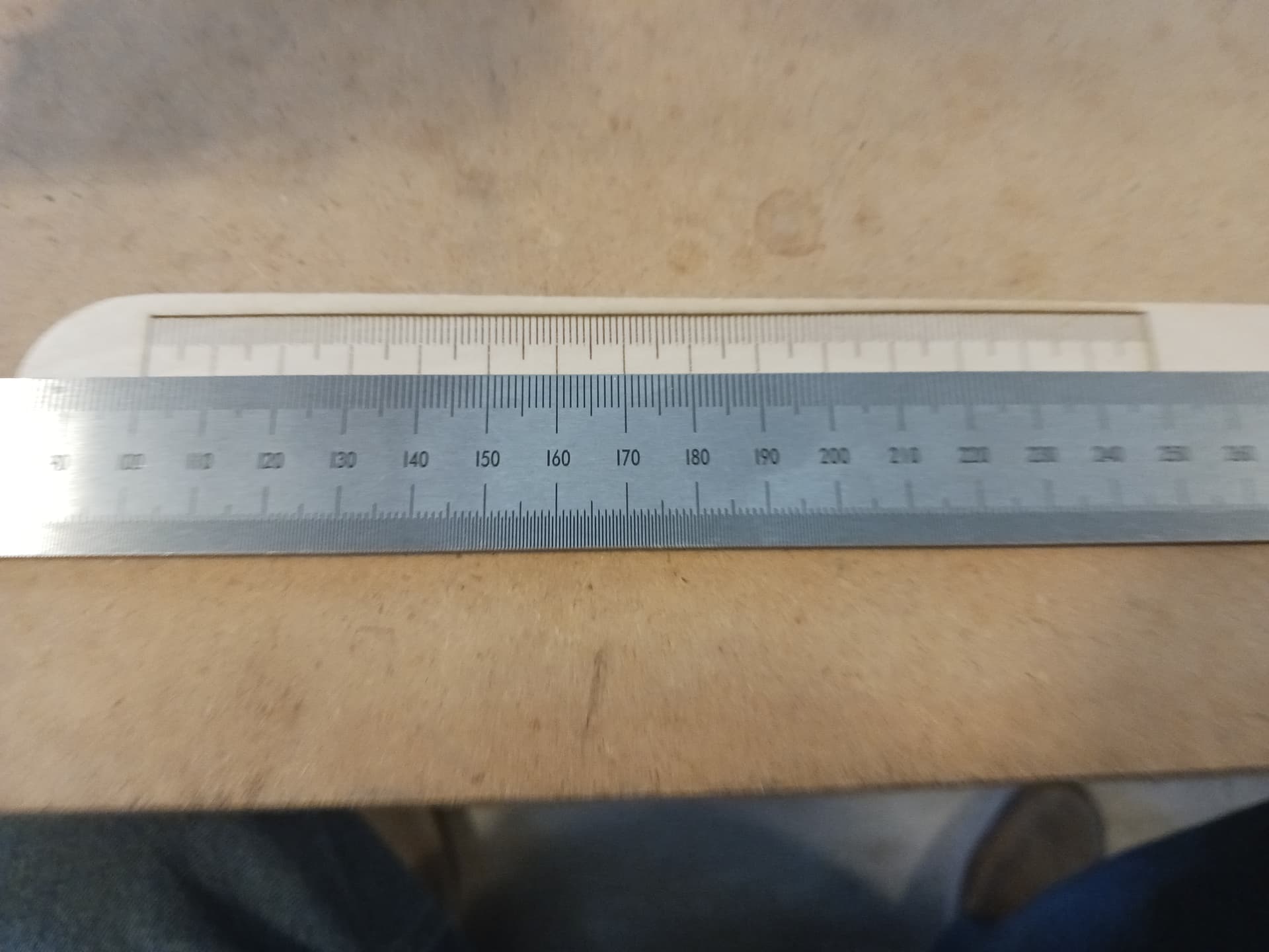
Ruler “0” at the 100mm mark on the commercial ruler…
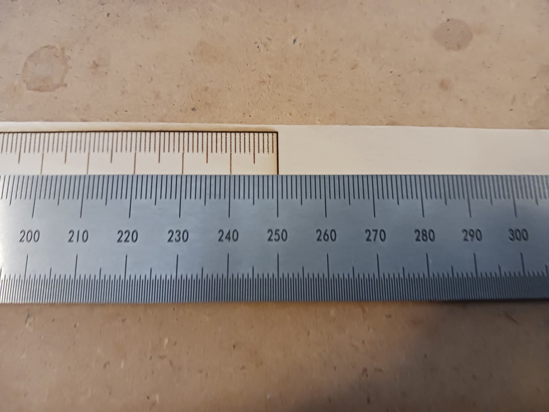
and ruler “150” at the 250 mark.
Still working the Z-axis design and printing some parts to test. I’m actually looking at a couple of different ideas.
Later.
7 Likes
Looks legit to me. Especially after multiple passes with the laser.
1 Like
one old squid to another, BZ
That is good work. Very cool build.
1 Like
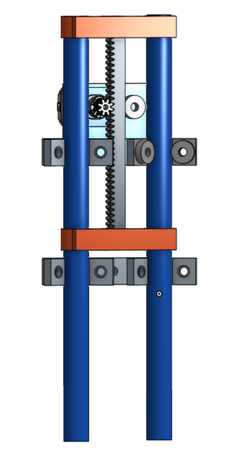
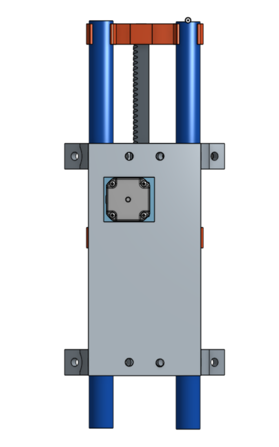
Here’s a first cut at a prototype Z-axis… but not entirely happy with it.

It runs up and down nice and smooth but is a little wider than I’d like. I need to cut a couple of pieces of conduit to to replace the ones shown. That will increase the range by another inch or so; i.e. 100mm plus vs the 80mm or so as shown in the video. Here’s a couple of assembly screenshots for the one in the video… again use your minds eye to supply the missing parts.
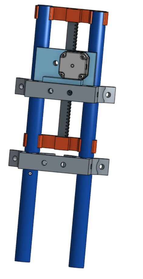
I’m also working on a second prototype – and printing parts right now – that is similar but fewer parts and more compact and no wider than the X-carriage.
Later.
1 Like
yeah, thats is mezmorizing. I wacthed it 3 or 4 times. Yes the full video not just up and down 4 times and thought it was on repeat, Strange how simple things can be, yet how much work can go into it.
1 Like
I wonder if we are looking at the testing for a new MPCNC.
2 Likes
It’s remarkable the similarities between my noodling on the MPCNC next thread and the machine being presented here.
I was thinking about integrating belts and not printable herringbone rack.
The more I’ve watched this thread, the more I see a brilliant, modular approach to building a machine.
It is well and truly a mostly printed CNC, and the concept has tremendous potential.
4 Likes
I mean why not. A rack and pinion Z would work just as good as a lead screw.
A new MPCNC needs to be different and DKJ…you are really getting my brain firing on a fresh spark plug here. Thanks for playing around and following this idea.
3 Likes
Oh, my! What kind words guys but… goodness! I feel as though I’m really just fumbling through this project… but I also know from experience that if I keep plugging away, I’ll eventually get something close to what I envisioned.
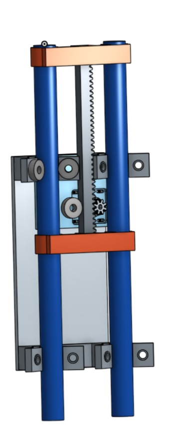
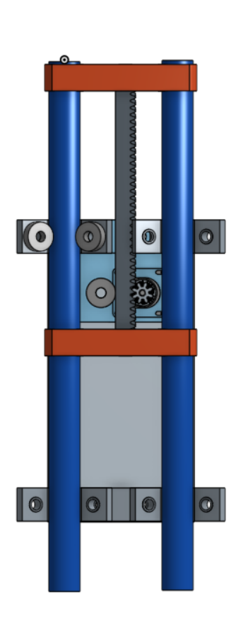
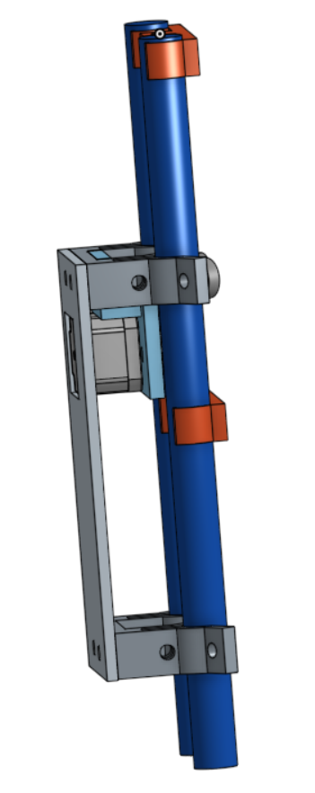
I repeated the Z-axis test of last evening after studying and reorienting the relative placement of the same parts on the assembly. I also laser cut a couple of iterations of the plywood backplate to mount and hold things together… and allow me to clamp the assembly in place on the X-carriage. The full range of motion is 100mm to ~120mm and feel that’s plenty for me…

Here are some screenshots of the “assembly”…
I’m self-taught pretty much on Onshape and I know I’m making lots of “rookie mistakes” so my documentation is really a mess. Rather that using Onshape’s actual Assembly functionality… I seem to do better “assembling” all the parts in one Part Studio… which is where I can make sketches (rarely fully defined… ![]() ) and design/print parts with relative position of mating parts in the same document. I’m not sure when the actual Assembly documents are supposed to come into play… after all the design work is done? Oh, well…
) and design/print parts with relative position of mating parts in the same document. I’m not sure when the actual Assembly documents are supposed to come into play… after all the design work is done? Oh, well…
Again, thanks for the kind words, Ryan and Jim… I’m blushing!![]() And, seriously, let me know how I can help. I’m happy to do this project all out in the open and don’t plan on taking any “trade secrets” with me to my grave. It’s great to hear you say, Ryan, that it’s got your “brain firing on a fresh spark plug”… just let me know how I can help keep it firing.
And, seriously, let me know how I can help. I’m happy to do this project all out in the open and don’t plan on taking any “trade secrets” with me to my grave. It’s great to hear you say, Ryan, that it’s got your “brain firing on a fresh spark plug”… just let me know how I can help keep it firing.
– David
2 Likes
Just keep messing around. I am learning a ton without having to do any work!!!
2 Likes
The one potential downside I can think of is friction/heat.
Though that would only be an issue if there are a lot of quick sequential moves. Something like drilling a bunch of holes could potentially have the rack moving back and forth quickly over the same section enough to start to build up some heat and potentially soften the plastic.
Obviously there are a couple of approaches to help prevent that. But it could also be fun to really push the mechanism to see if it can even reach that point ![]()
1 Like