With @jhitesma’s recent reappearance in the forum and his plan to build a LR4 – and reminiscing over past projects – I’m really tempted to attempt another machine build. My initial thought was to build a small-ish LR4 (I’ve never built an actual LowRider ) but as I continued to ponder the idea, I realized I have enough dismantled MPCNC- and LR-inspired machines/parts stashed away, that I should be able to easily build another complete machine from my junkbox. I also enjoy fumbling around in Onshape and with the success of my previous R&P MPCNC still fondly in mind, I’ve decided that rather than a LR4 (that I don’t need or have room for), I want to give printed R&P another shot on a generic machine design that I can build entirely from my junkbox and at any convenient size… just for the fun of it.
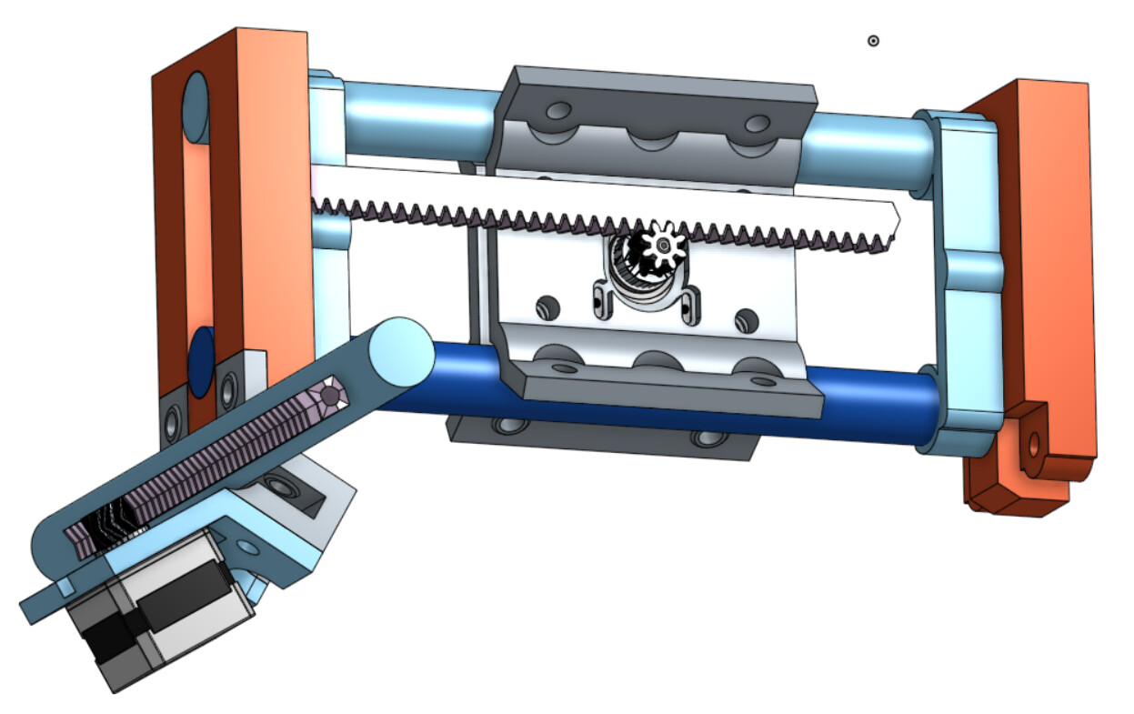
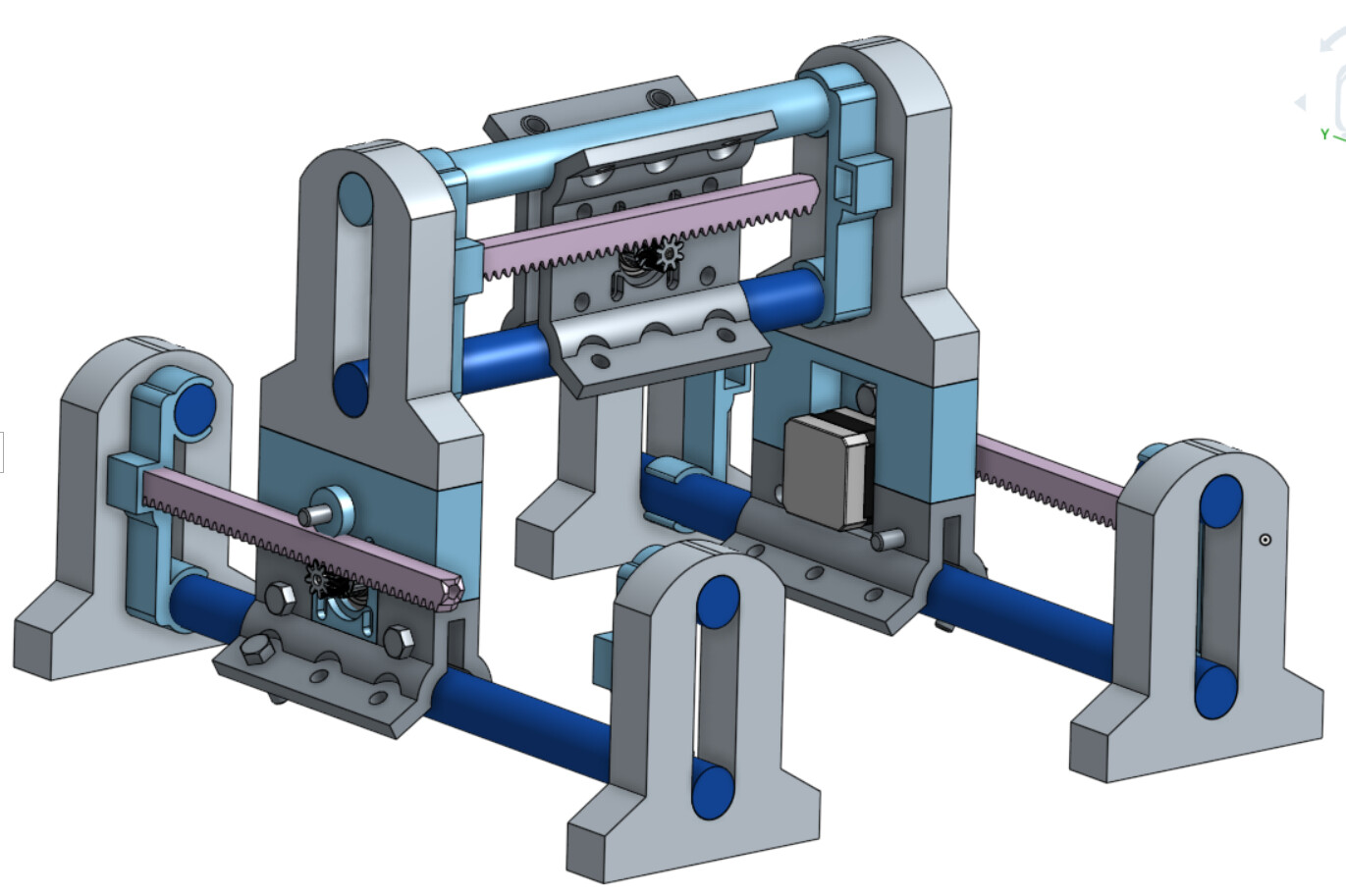
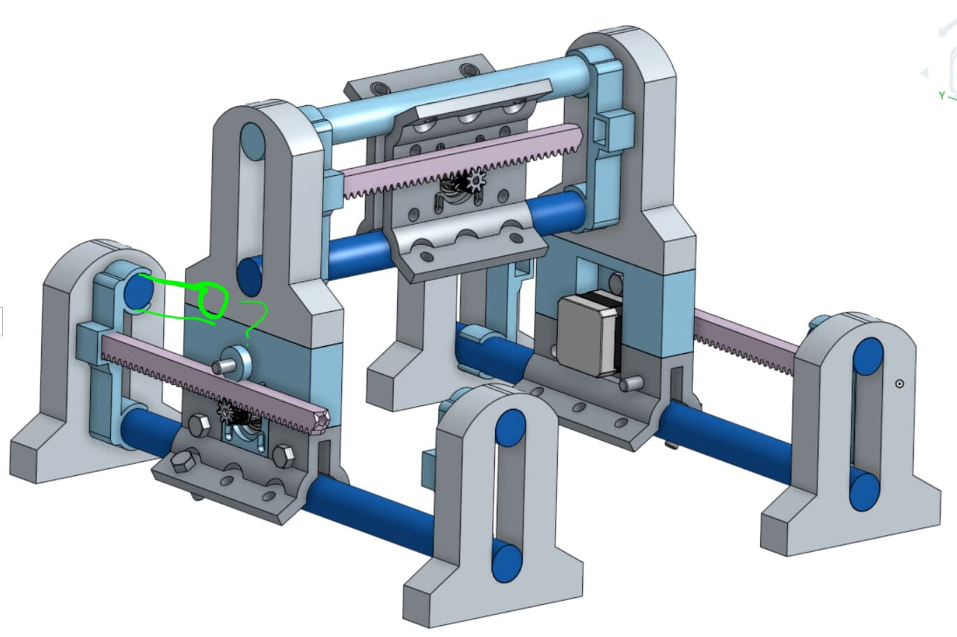
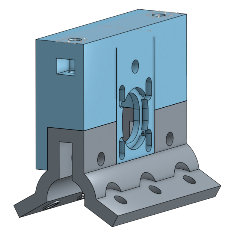
Drawing from my previous X/Y drive for the R&P MPCNC and FoamRipper carriage ideas, I’ve started designing and printing parts for a generic R&P X/Y/Z machine. I’m using Onshape and have some first-SWAG parts in work to start figuring out how to incorporate R&P on the X and Y axis… with Z to come later. So far this is what I envision. You can use your mind’s eye to supply the missing parts …
I’m really enjoying doing some design work again… and my Onshape skills are slowly starting to improve. I’m still adjusting things and adding support structures so that I can print parts using “No Support” in PrusaSlicer.
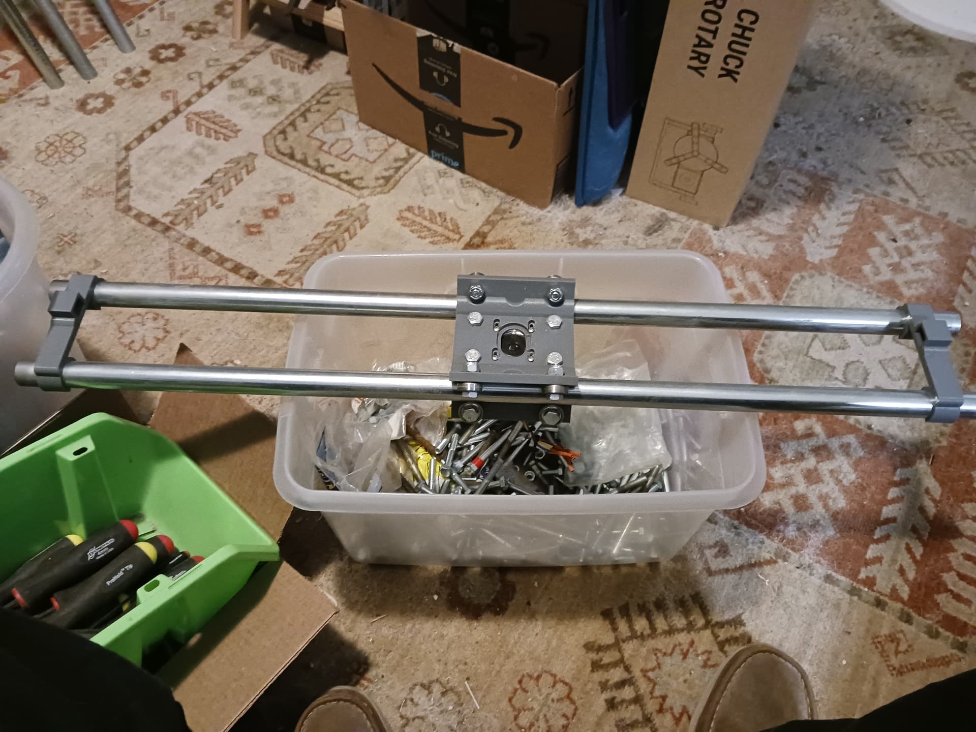
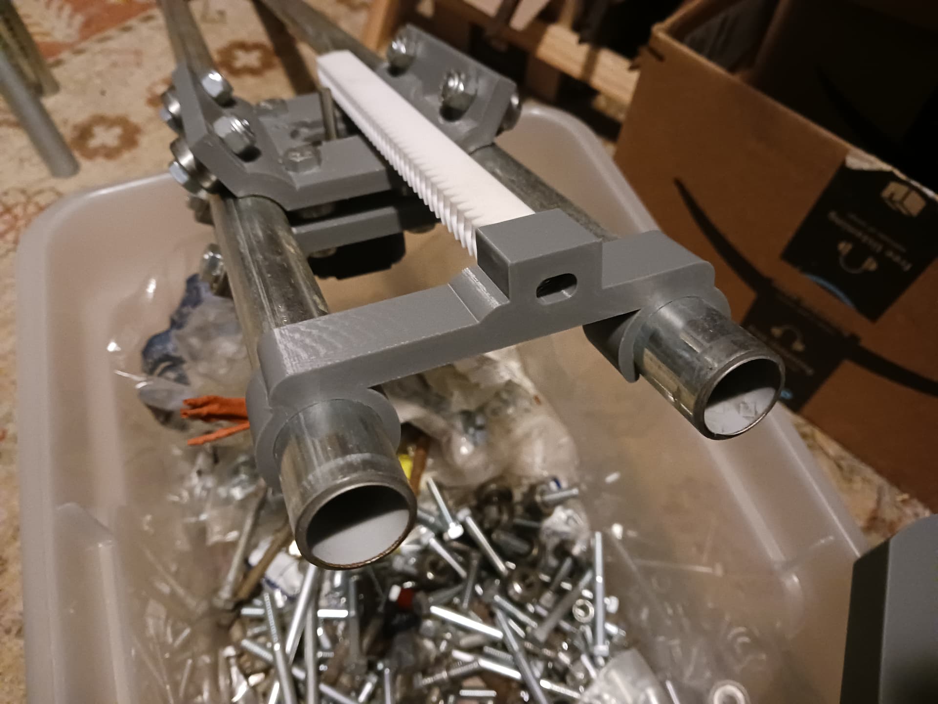
My latest change was to widen the track of the modular roller assembly (foreground) borrowed from the R&P MPCNC. It’s looking sort of like this now…
I have no expectations for the strength and rigidity of this machine… so don’t start asking about a router mount for it . This particular machine will never really be tested for strength/rigidity and I doubt it will ever carry more than a laser or pen. I’m mostly adjusting things using my TLAR strategy and purposely not softening sharp edges until things are fitting properly.
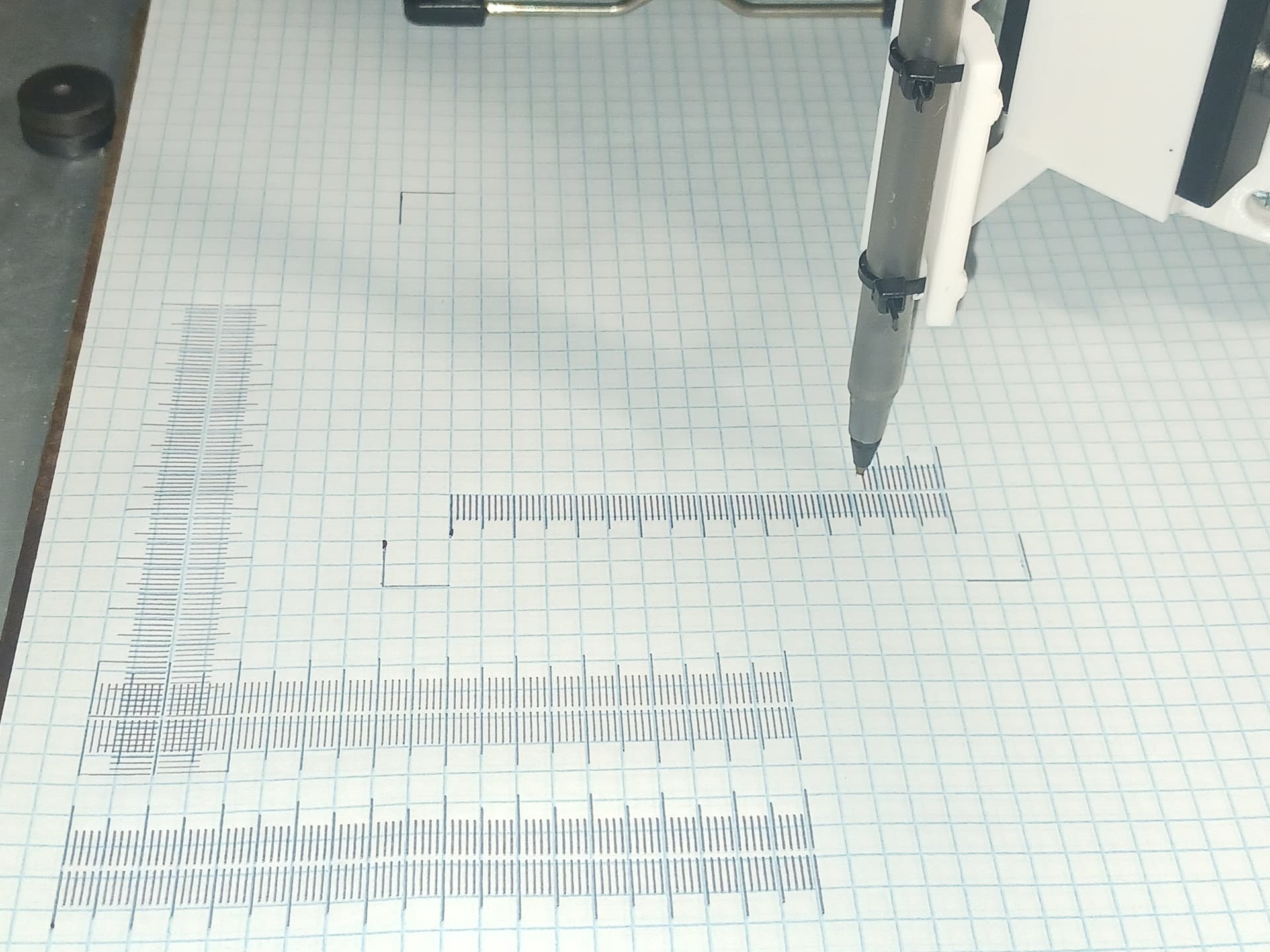
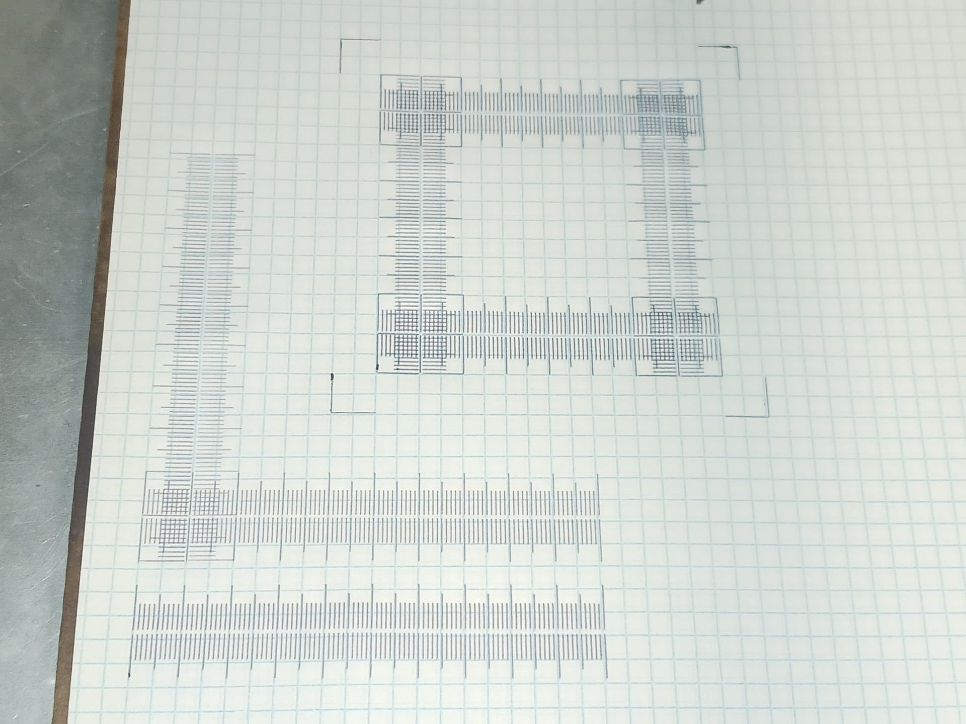
The printed rack and pinion have actually proven surprisingly accurate in my experience… though I’m sure that will suffer long-term if the machine is used heavily. In previous testing I’ve been able to calibrate the R&P axis and draw an assortment of Jamie’s (@jamiek) rulers from his test pattern generator…
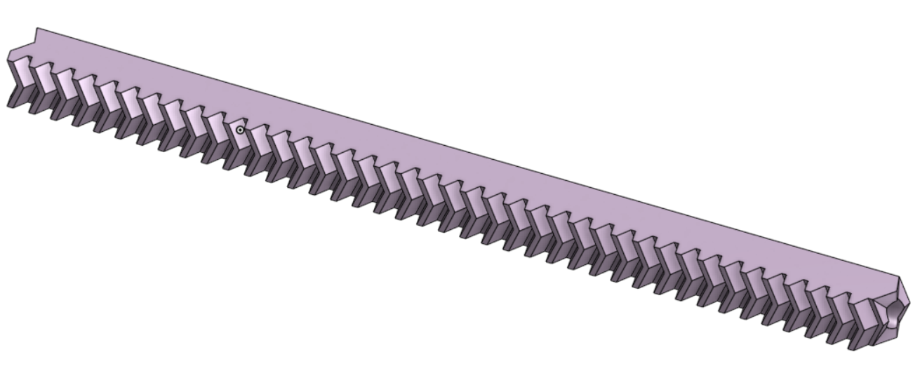
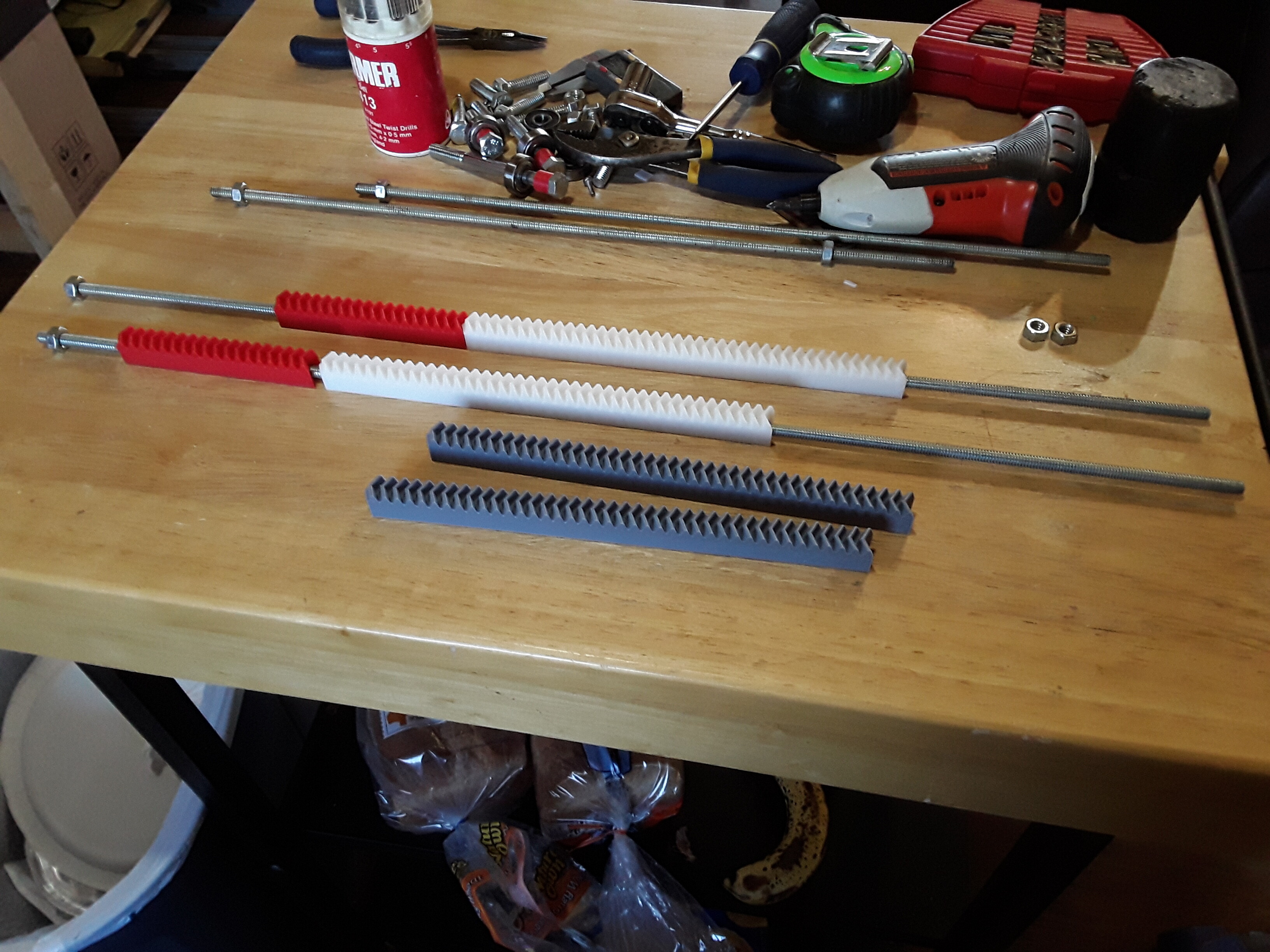
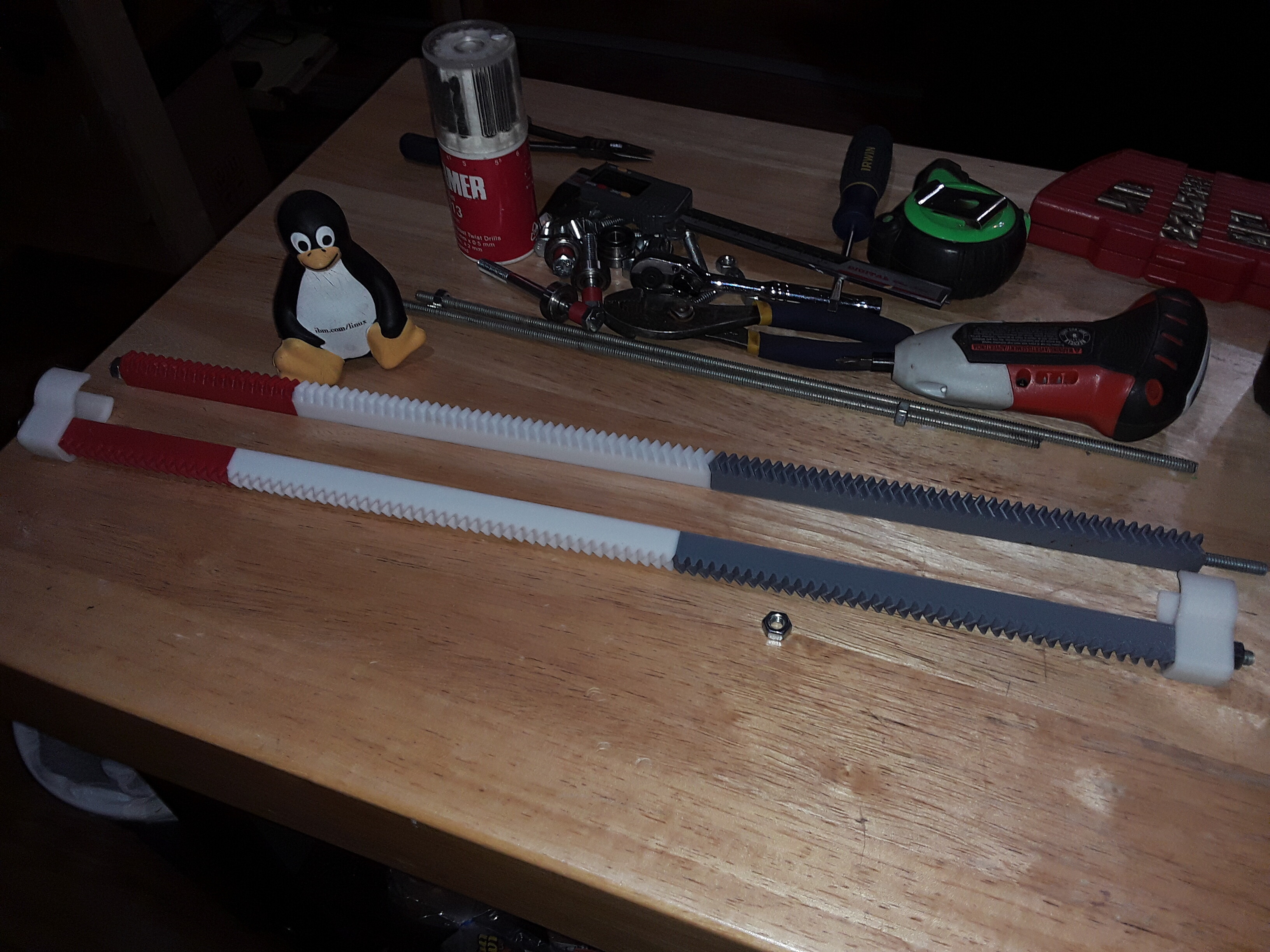
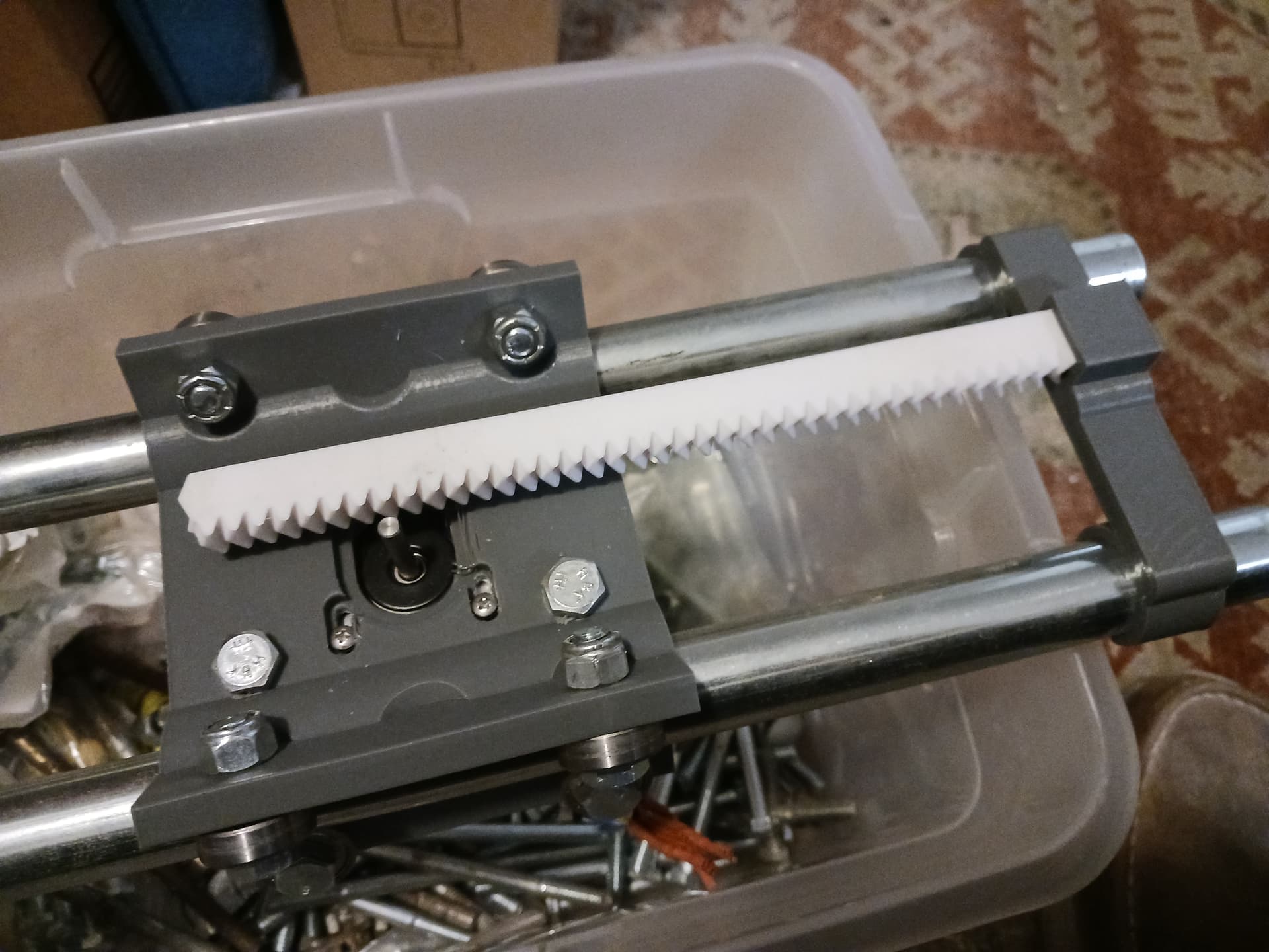
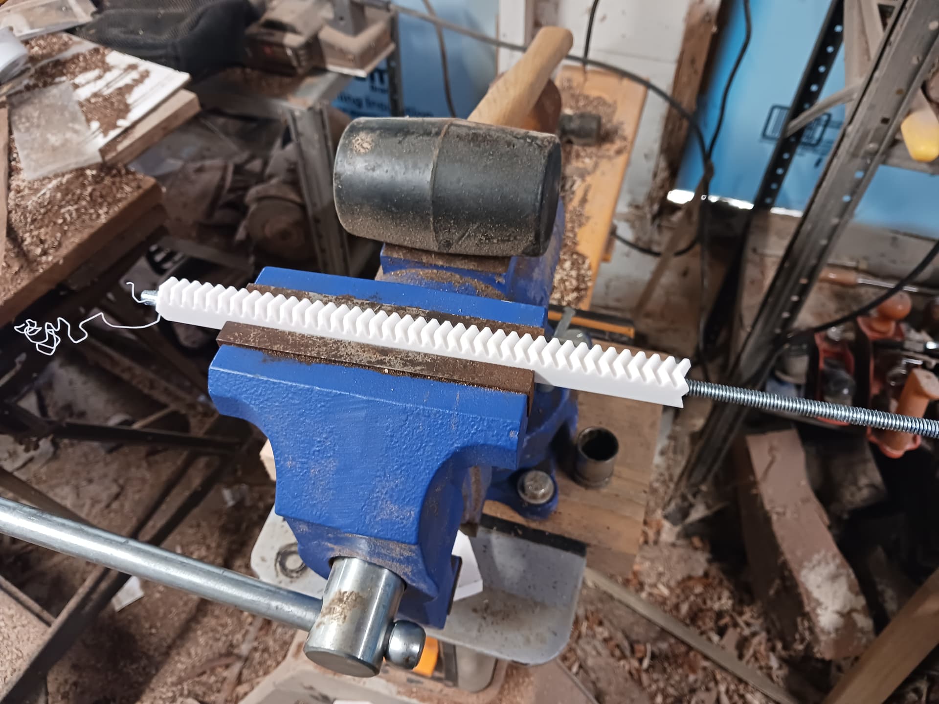
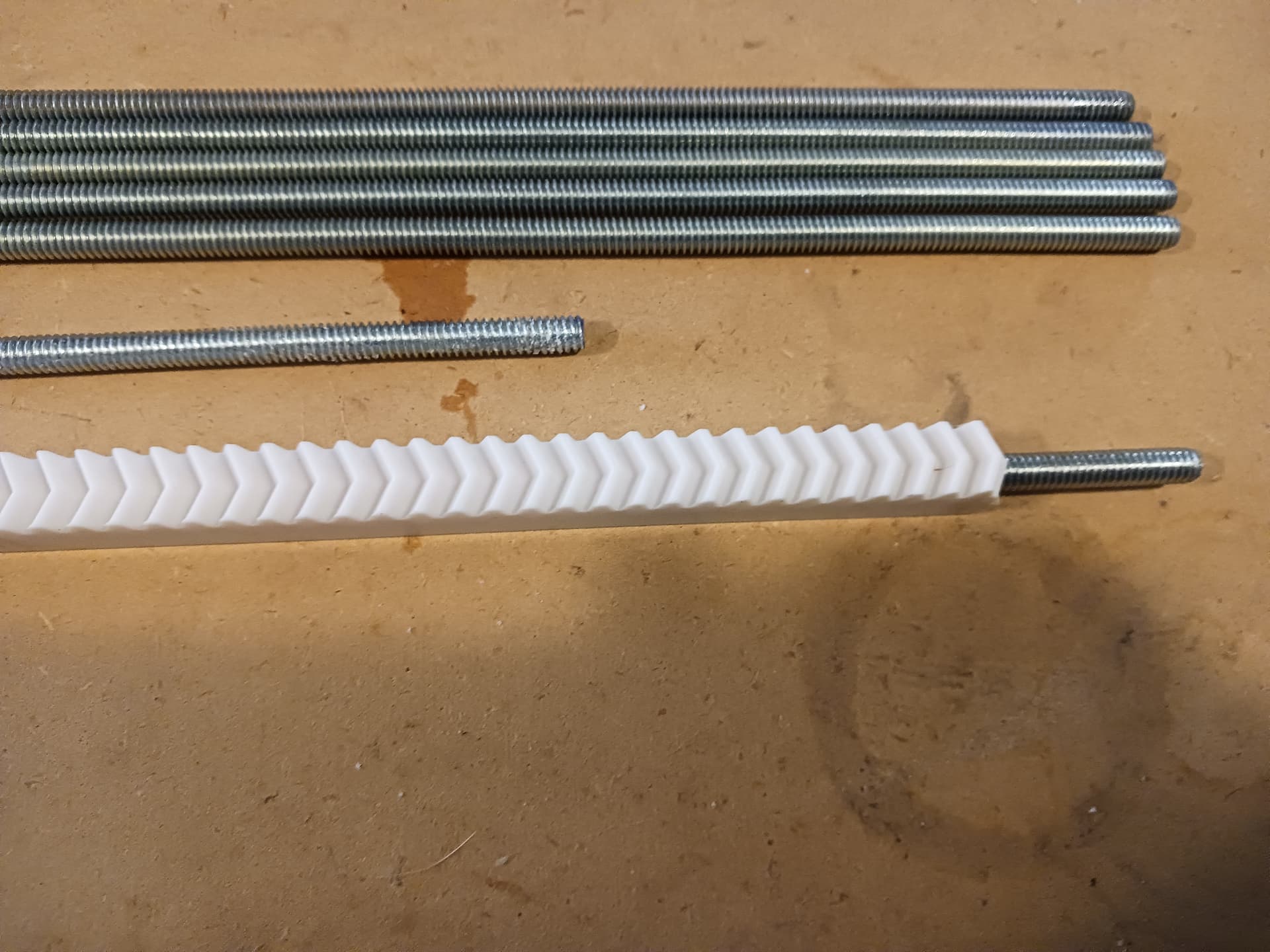
Despite being segmented and limited to about 40 teeth per segment so that I can print it on my Prusa MK-3S printer’s ~8" square bed, the rack segments are strung up on a 1/4" threaded rod, cut to the desired length for each axis…
The herringbone teeth of the rack and pinion appear to minimize any backlash (there are always points of engagement between rack and pinion?) and they also tend to track quite straight as seen in this early Phlatprinter-inspired machine…
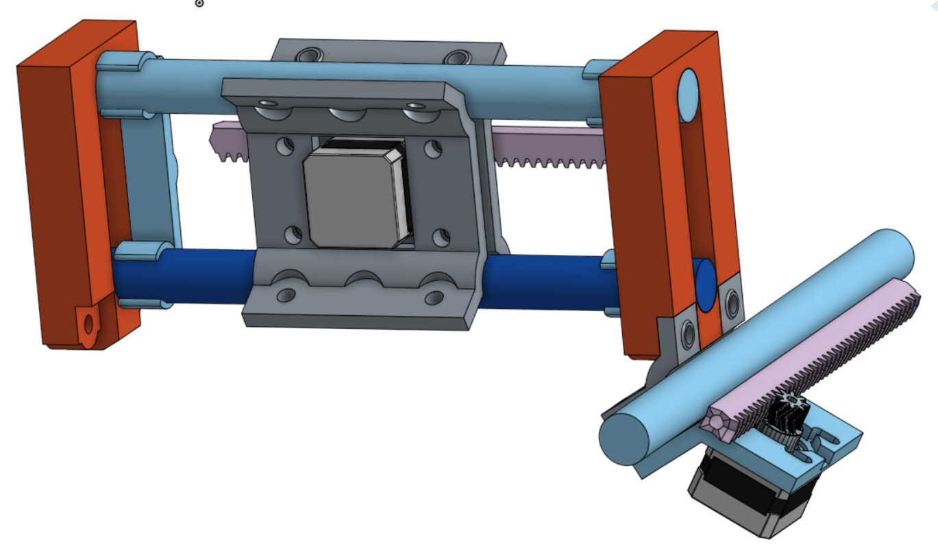
As I started working on the gantry ends and Y-axis support feet and thinking about how I was going to start mocking this machine up, I realized I might be able to reduce the number of unique parts by reusing as many parts as possible. After fiddling around for a few hours in Onshape I was able to make every axis end support similar, with the conduit and rack ends all captured the same way. That necessitated ditching the tractor configuration of the R&P MPCNC and using a stretched MPCNC-conventional tractor, altered to incorporate a near-identical motor and R&P relationship as in the gantry carriage.
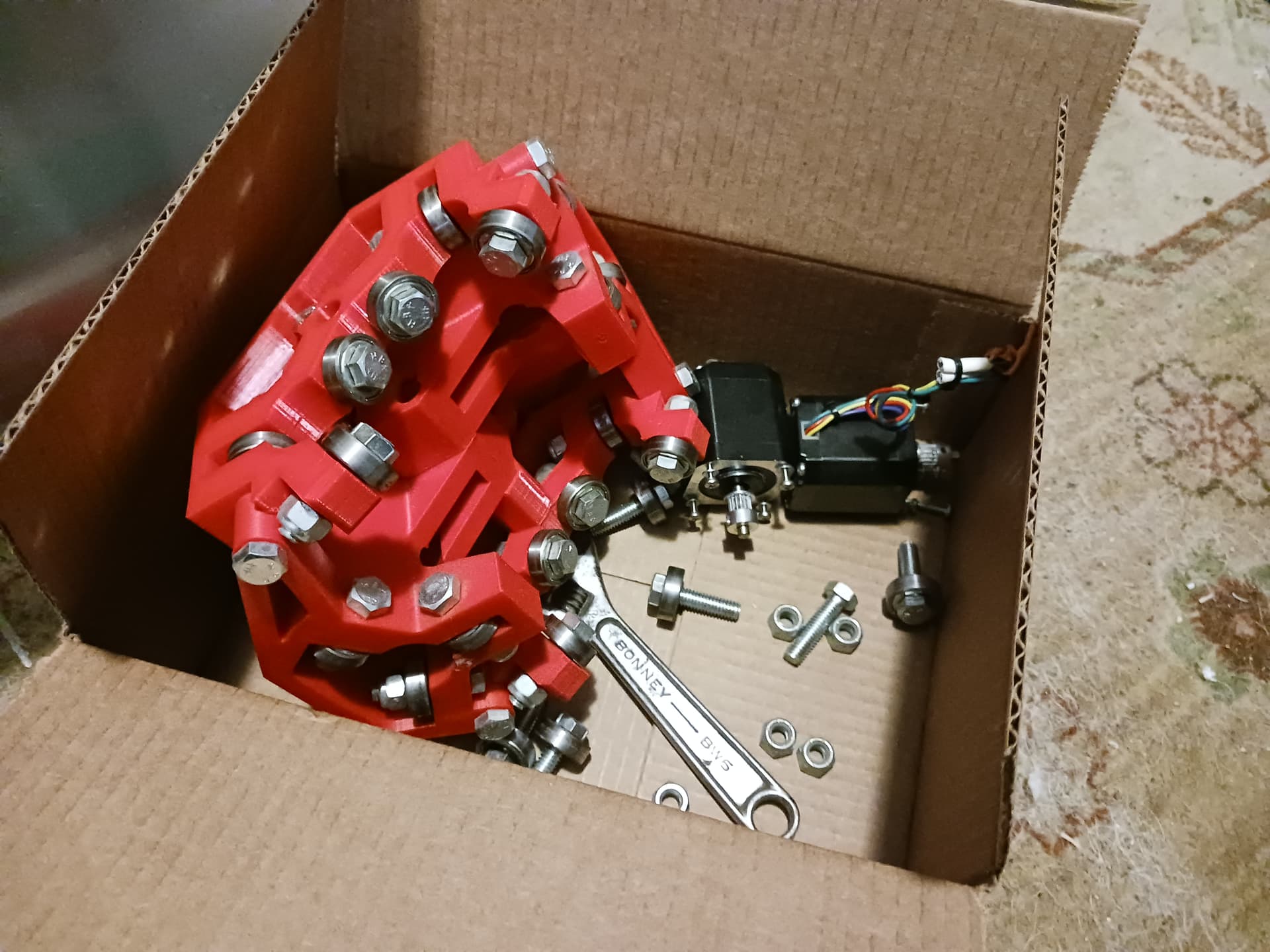
As most of the prints take a few hours, in addition to the Onshape activity I’ve also started gathering up tools and rummaging around in my junkbox. I found an old MPCNC 525(?) core and a couple of tractors which yielded a lot of 5/16"(8mm) bolts and 608 skate bearings. I also found another big box of bolts and bearings that must have resulted from all the machine dismantlement I did prior to my moves to San Antonio and then back to my home here in East Texas.
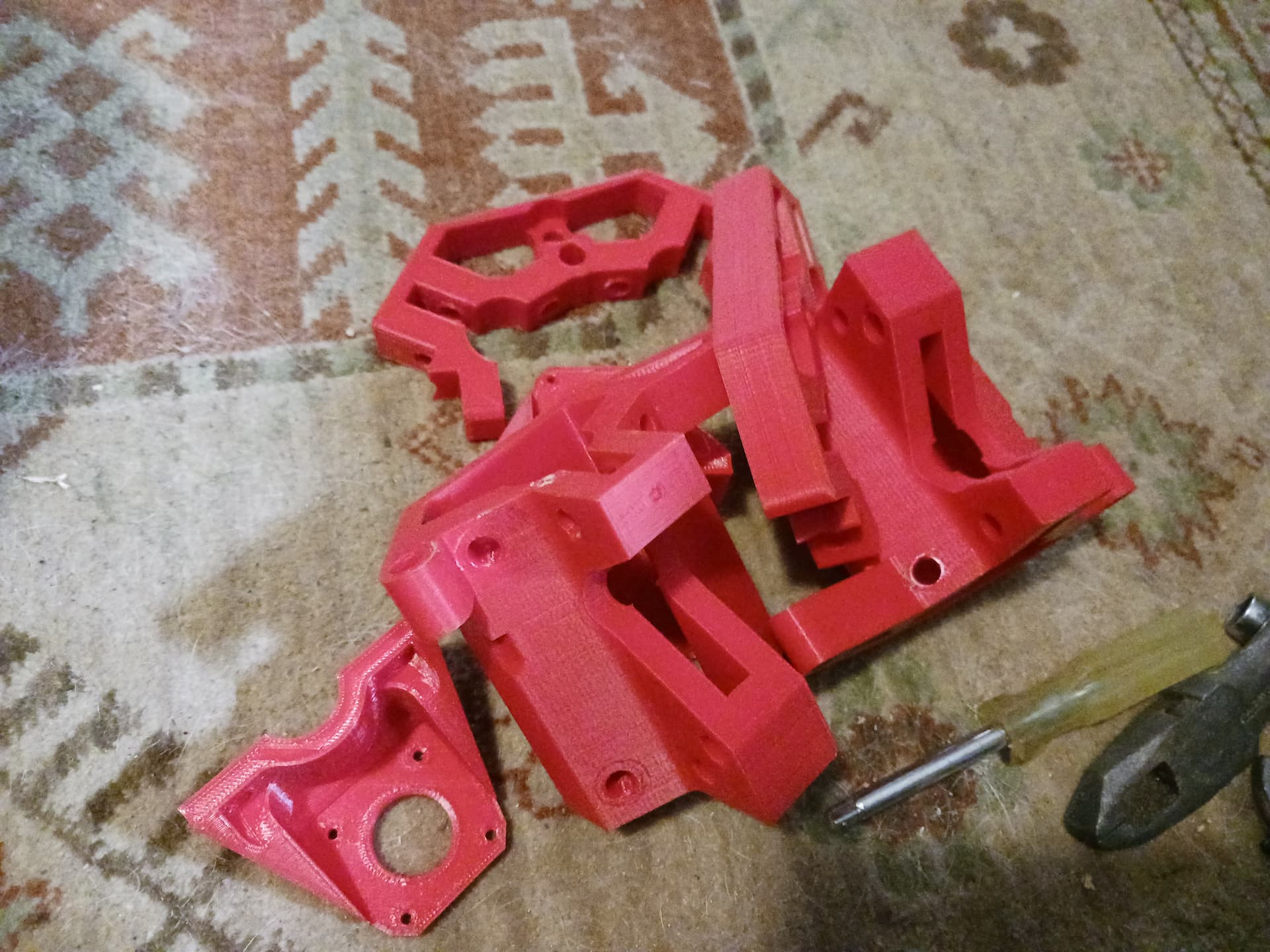
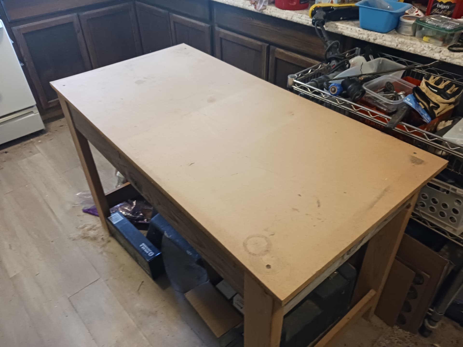
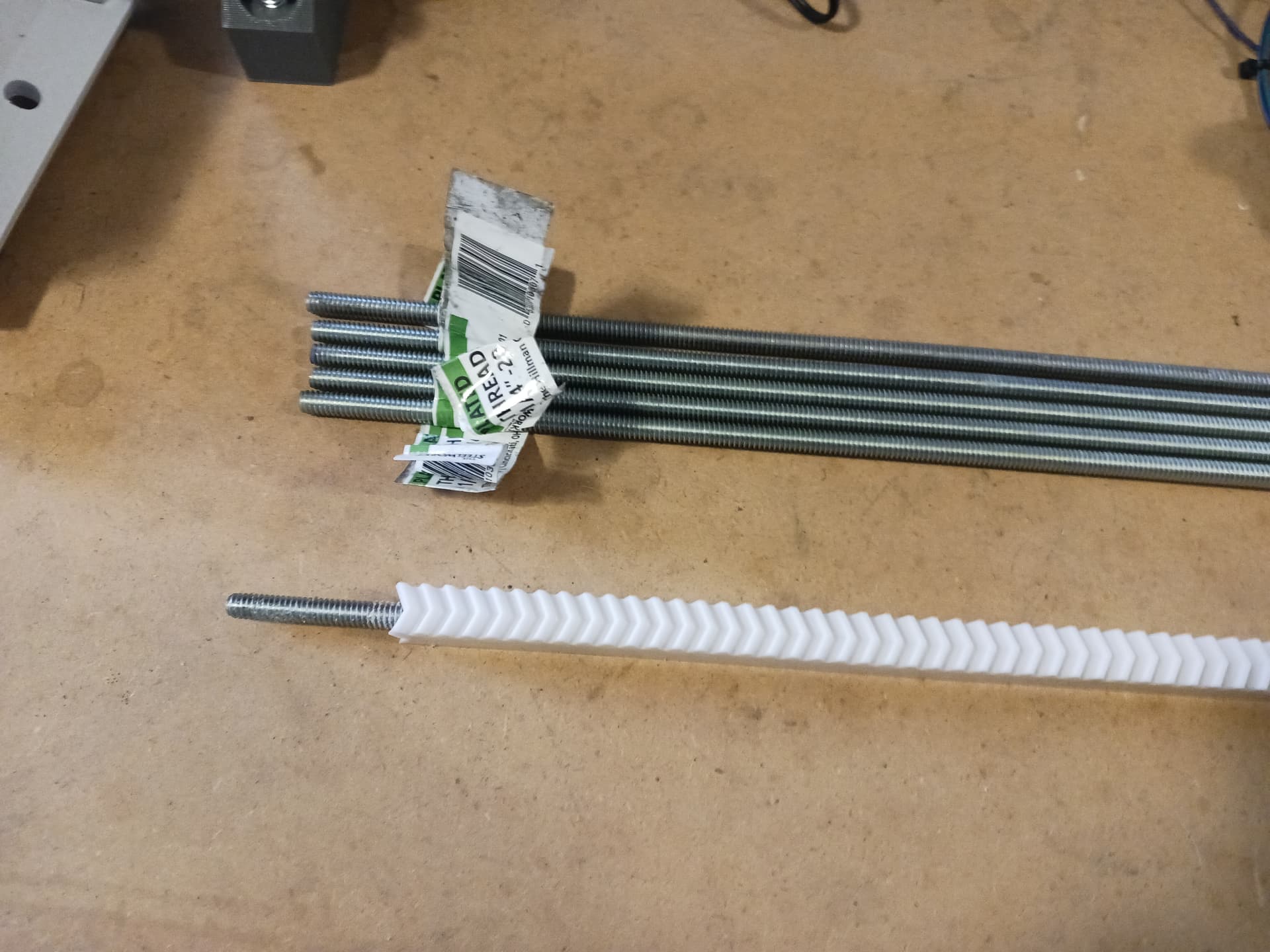
As I built only a couple of R&P machines prior and gave one away to Jamie, my junkbox is apparently lacking 1/4" threaded rod for the segmented rack so I will probably have to break down and buy a few 3’ lengths from Lowes. I’ve got tons more parts printing to do and I’ll start cleaning off a work table to assemble the machine on. Unfortunately I also ran out of my “signature white” Sunlu PLA+ filament so I put a couple of rolls on order from Amazon… and the prototype machine is gonna be an ugly gray.
So much fun to jump back and forth between CAD and prints, and satisfying to see stuff come out of the recycled parts boxes back into functional prototypes.
For the lower axis, how do the upper rails interface with the carriages? Don’t you need bearings of some kind where the tube will go through the carriage?
This layout is very similar to the modular system I noodled on in the MPCNC next thread, except totally different . I like printed rack and pinion drives, so it makes me smile to see it.
I love the way you stack the rack and pinion on threaded rod. Common and inexpensive raw material, great for this application.
Hey, Jim! Thank you for the kind words. This jumping back and forth between design and prototype build is fun, isn’t it? I wish I had had CAD tools and 3D printers like this when I did this stuff professionally. Being a Navy-trained tech initially, before becoming an engineer, I always enjoyed my time in the lab… many late nights and fond memories!
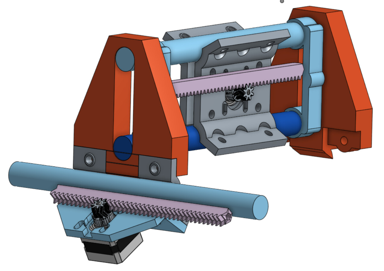
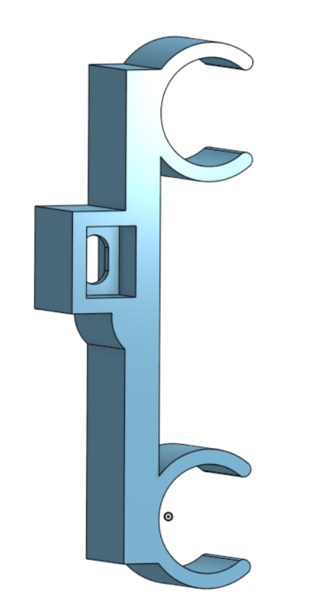
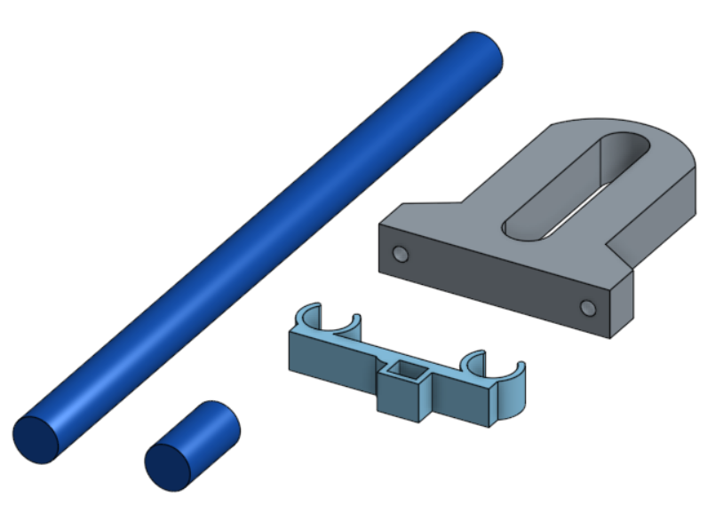
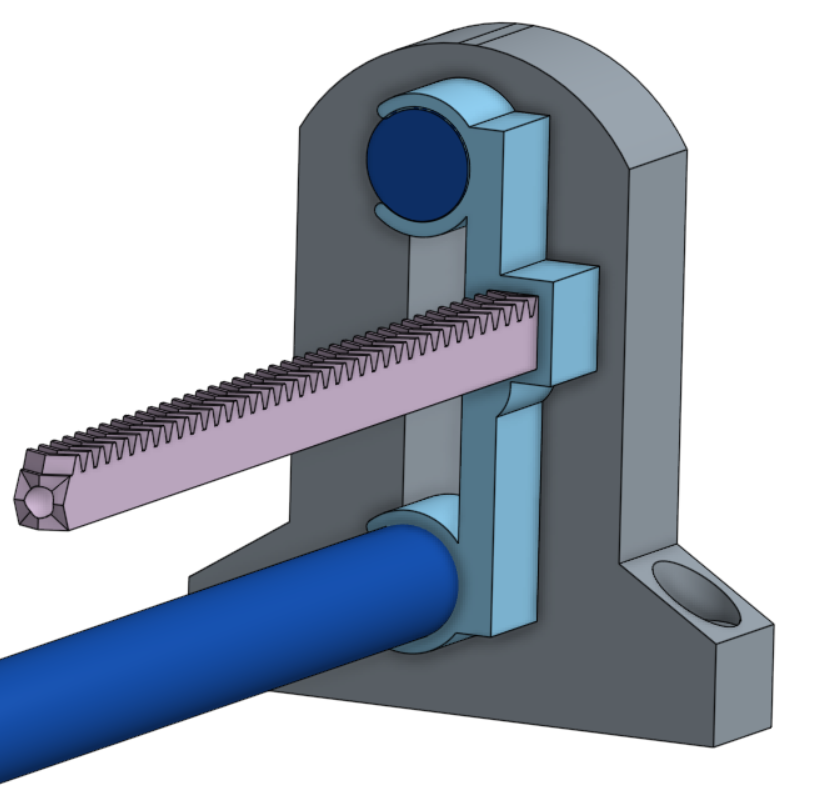
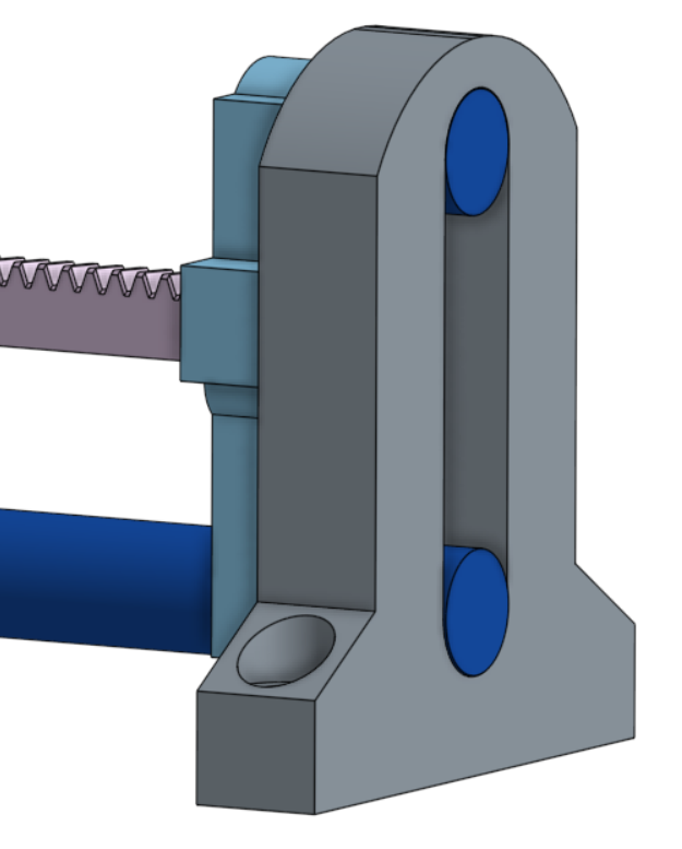
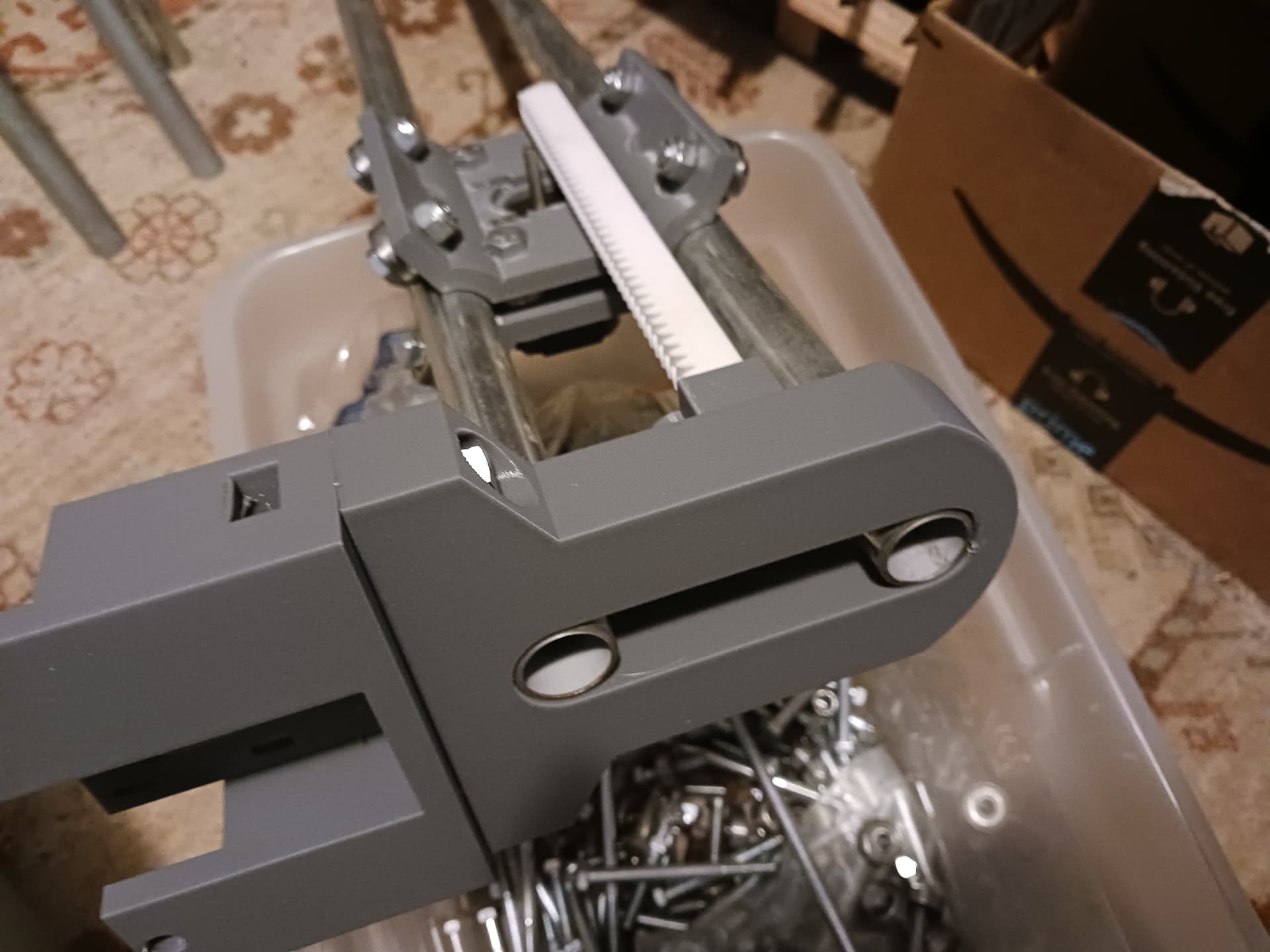
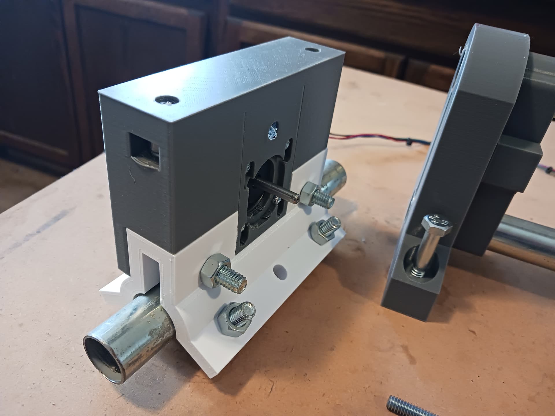
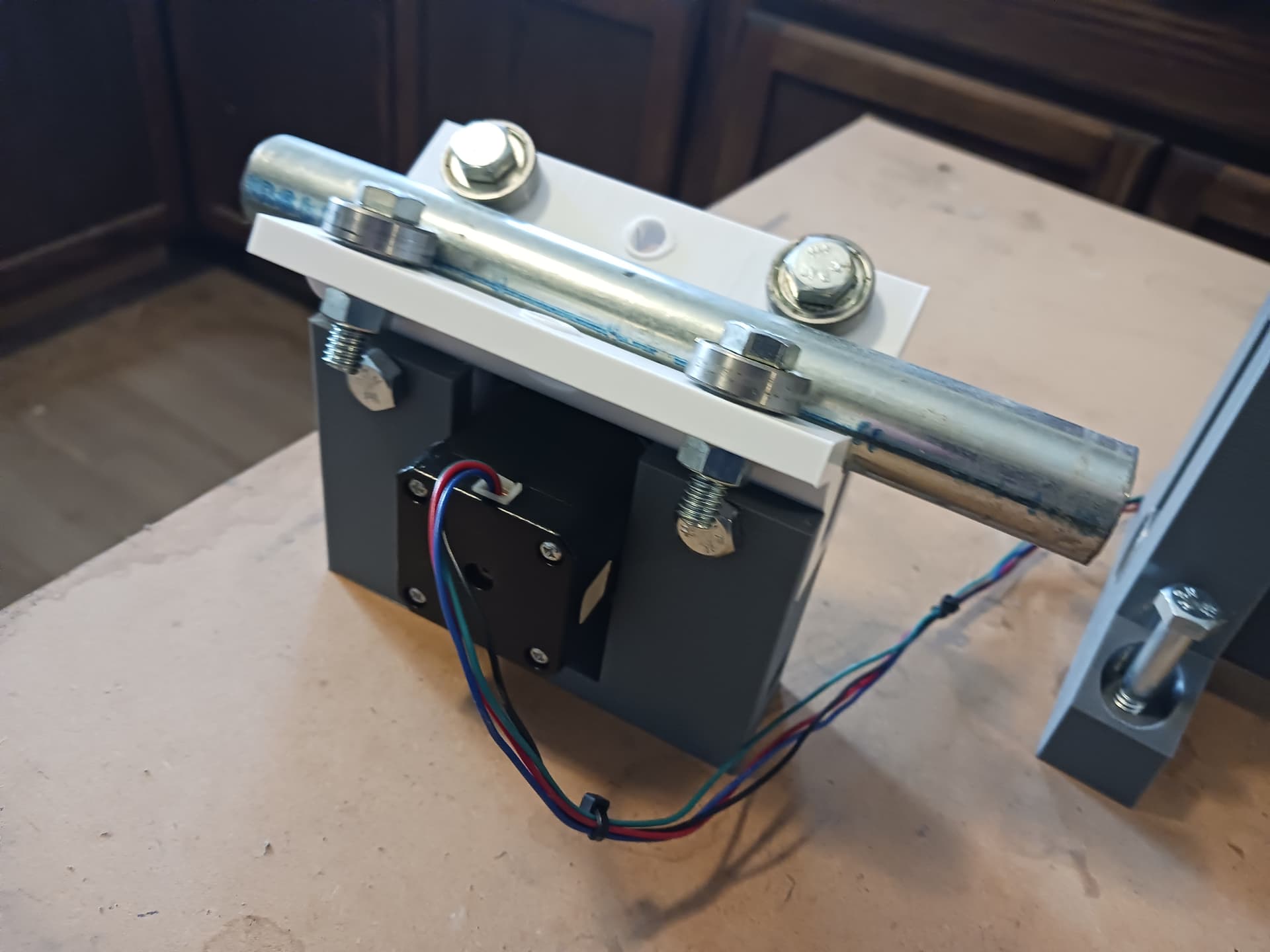
I’m trying to “standardize” the axis ends by using the same printed parts over and over. These 3/4" EMT “conduit clips” snap on tightly to hold the upper and lower rails of each axis and actually set the spacing between them… they also capture the ends of the rack.
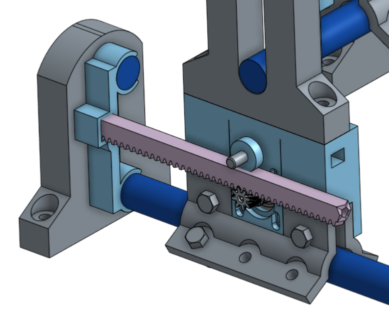
Each end of the gantry assembly then connects to and captures the lower rail with an MPCNC-style roller/tractor assembly… just to keep this all V1-relevant.
I see what you are saying. You either don’t need the rails at all the assembly will be fixed on both sides. Or…you add the rails and some bearings to give it a tiny bit of extra rigidity.
How much rigidity is required for this silly machine to sling around its own weight… and maybe a laser or pen? I’ll leave any real rigidity testing as “an exercise for the reader”…
As stated earlier, I have no real expectations for this machine, other than it should be capable of accurately carrying around a laser or pen… as machines I’ve built in the past have. I think it should be able to accurately laser a ruler or two…
I’m just happy to be actively doing this stuff again… and hoping the malaise of the past 4 - 5 years is behind me. Closing in on 79 years, I feel like my “rainy days” are now… and I’d better get with it. At this late date I’ve got no guarantees I’ll have the energy, mental faculties, or time to put it off any longer.
Enough! I’ll be happy to point you guys to my Onshape documents if you’re interested… and want to correct my mistakes? They’re messy and not elegant at all but I should be able to clean them up enough to contain just the parts for this project. I’ve always been a “seat-of-the-pants” engineer and am quite disorganized… so you’ve been “warned”.
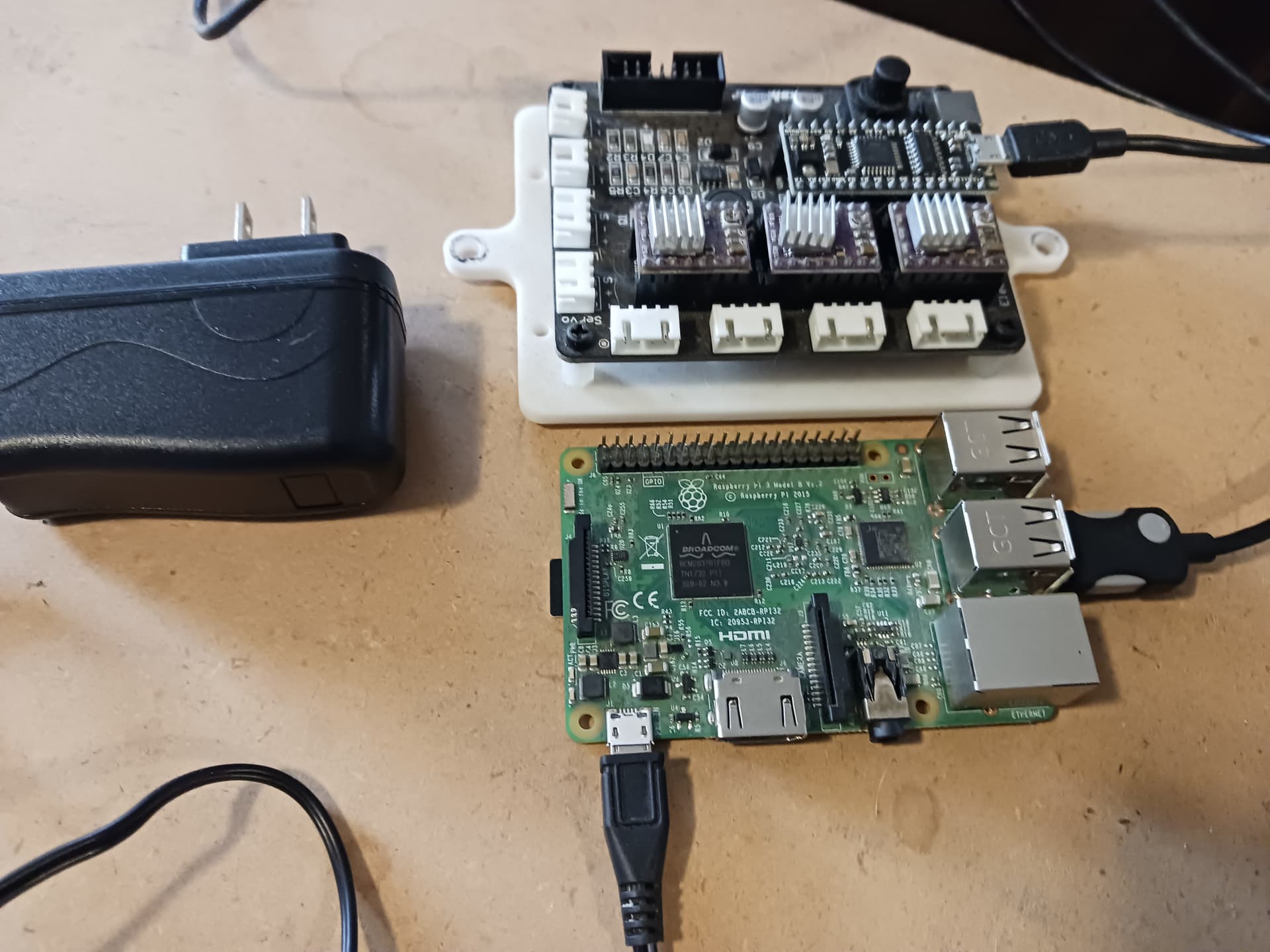
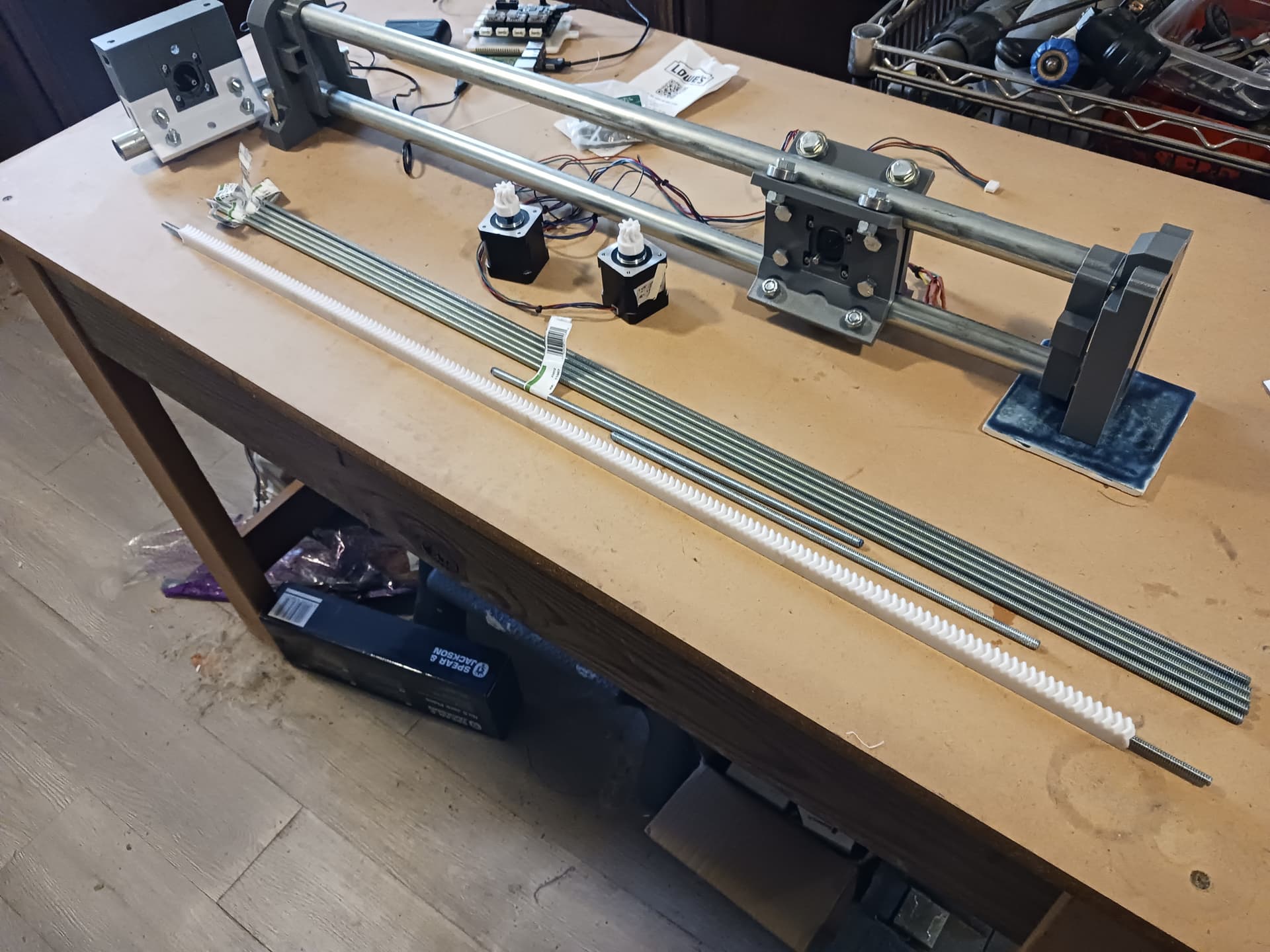
So I rounded up an Raspberry Pi 3B+ loaded with Jeff’s (@jeffeb3) V1Pi image and a little Arduino Nano-based 3-axis CNC board running Grbl 1.1h… all from my stash of parts! It all checked out…
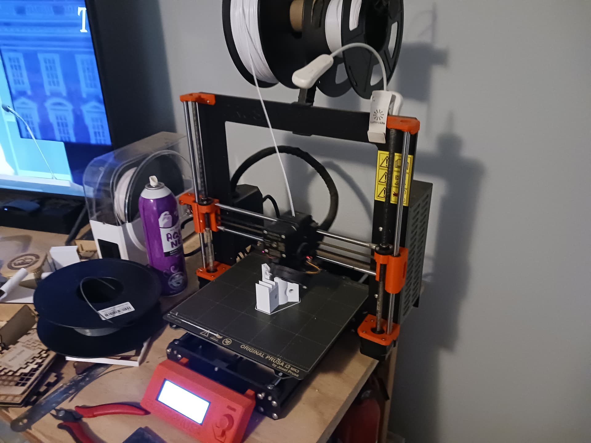
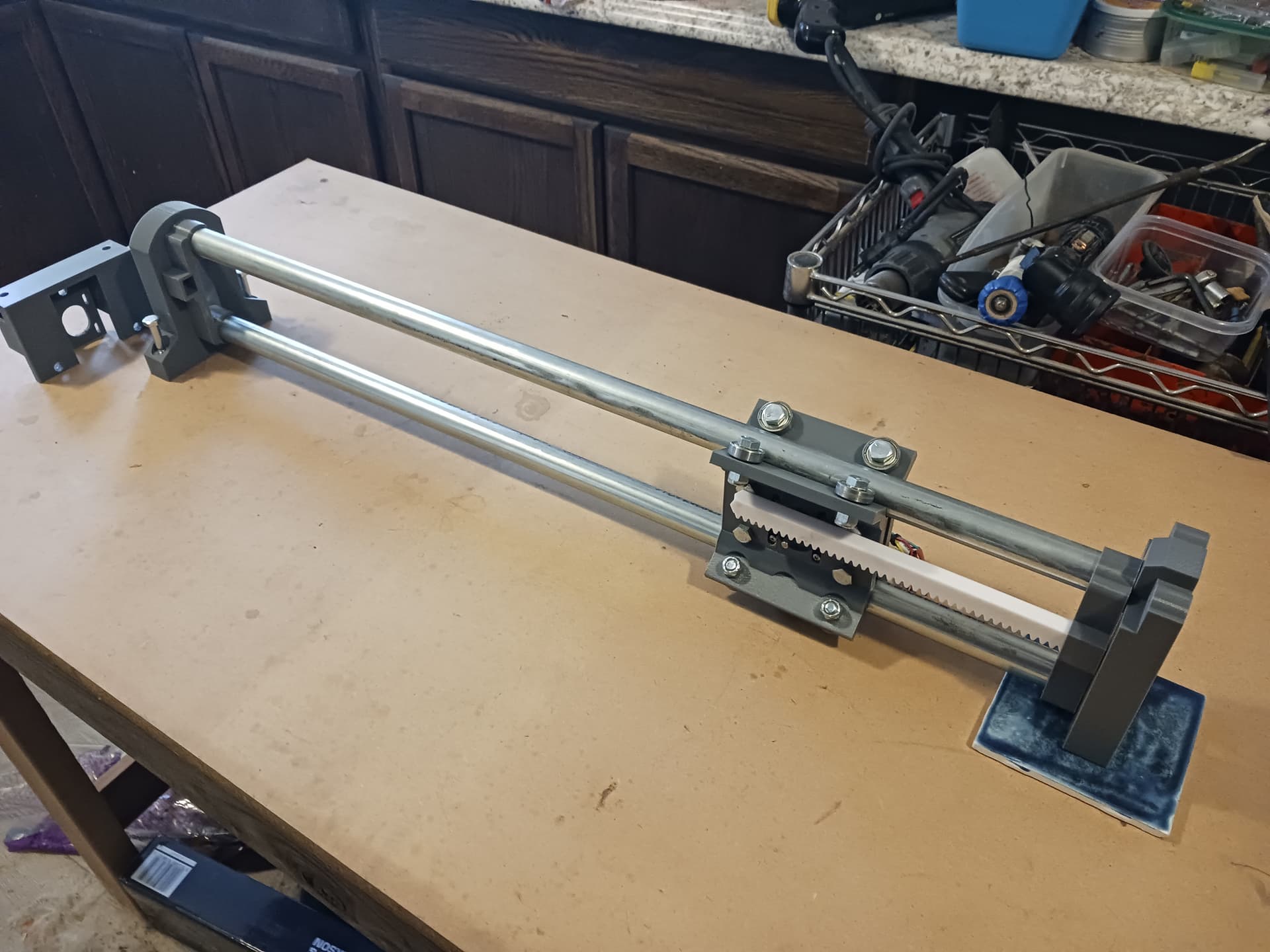
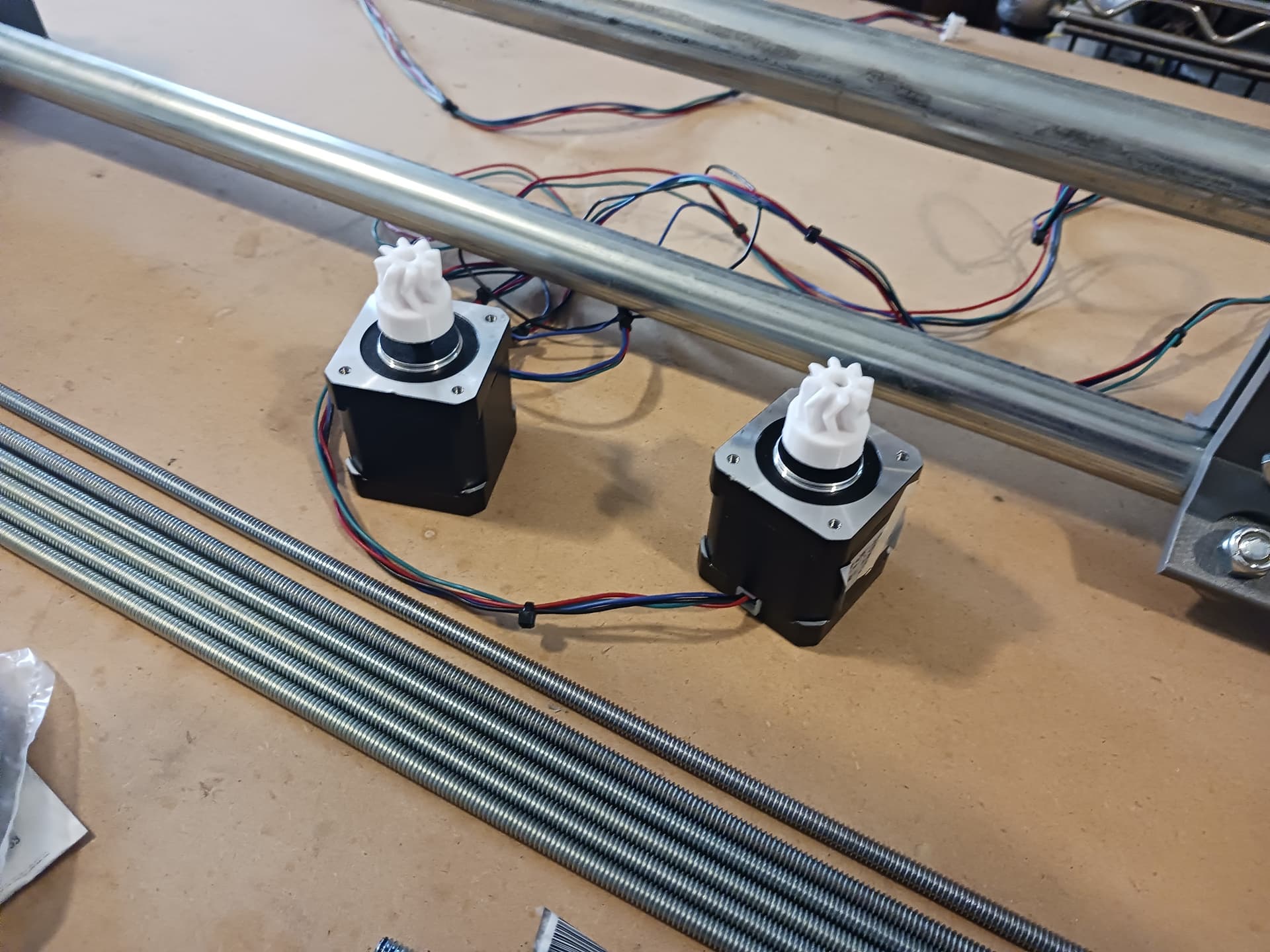
My tractor print finished. I had also discovered that I had a new roll of white Inland PLA+ so was able to do the tractor in my “signature white”. I then fit-checked it with the motor mount I’d already printed to insure all is workable before committing to printing all the other parts. Everything fit well enough to proceed…
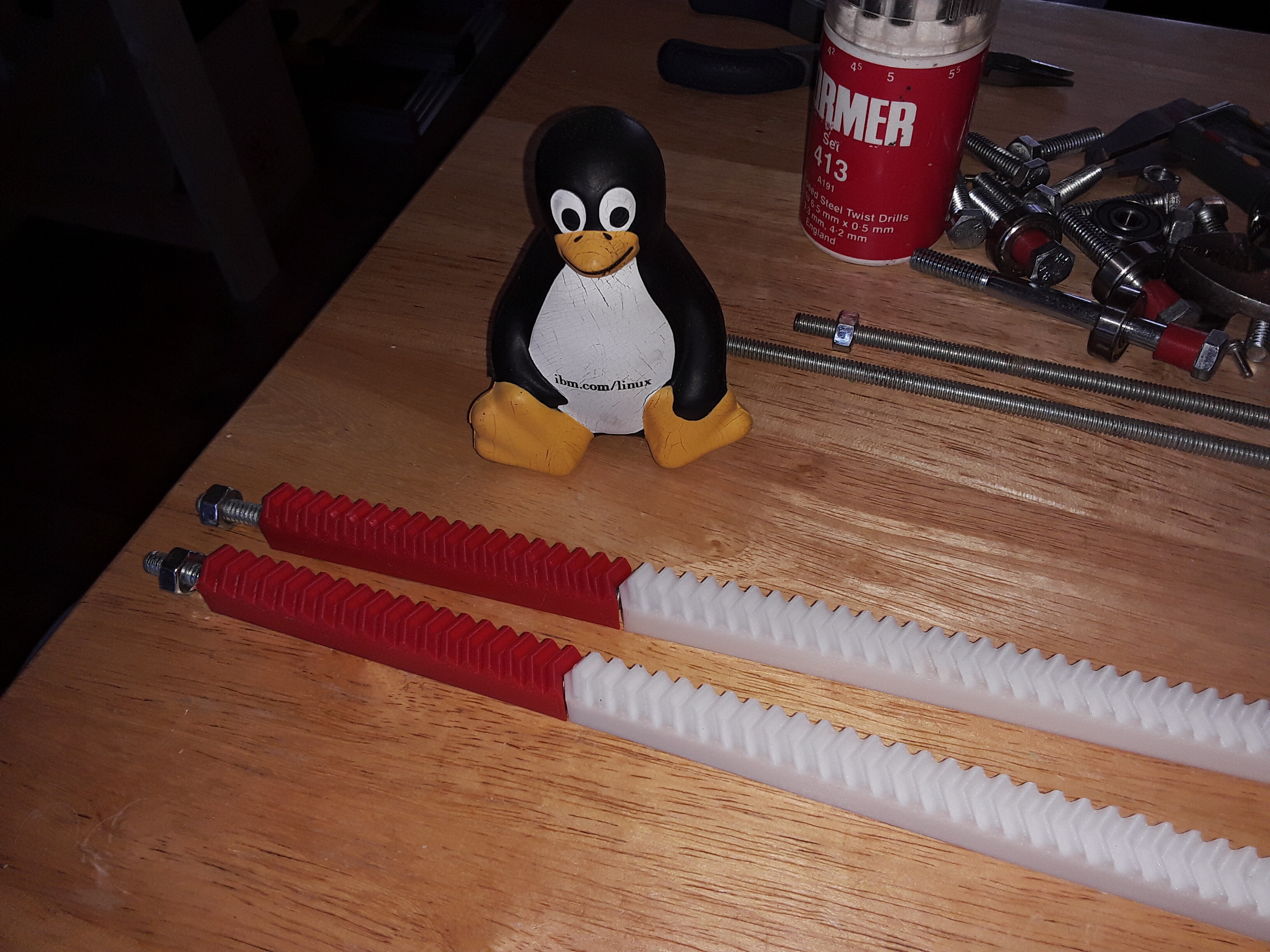
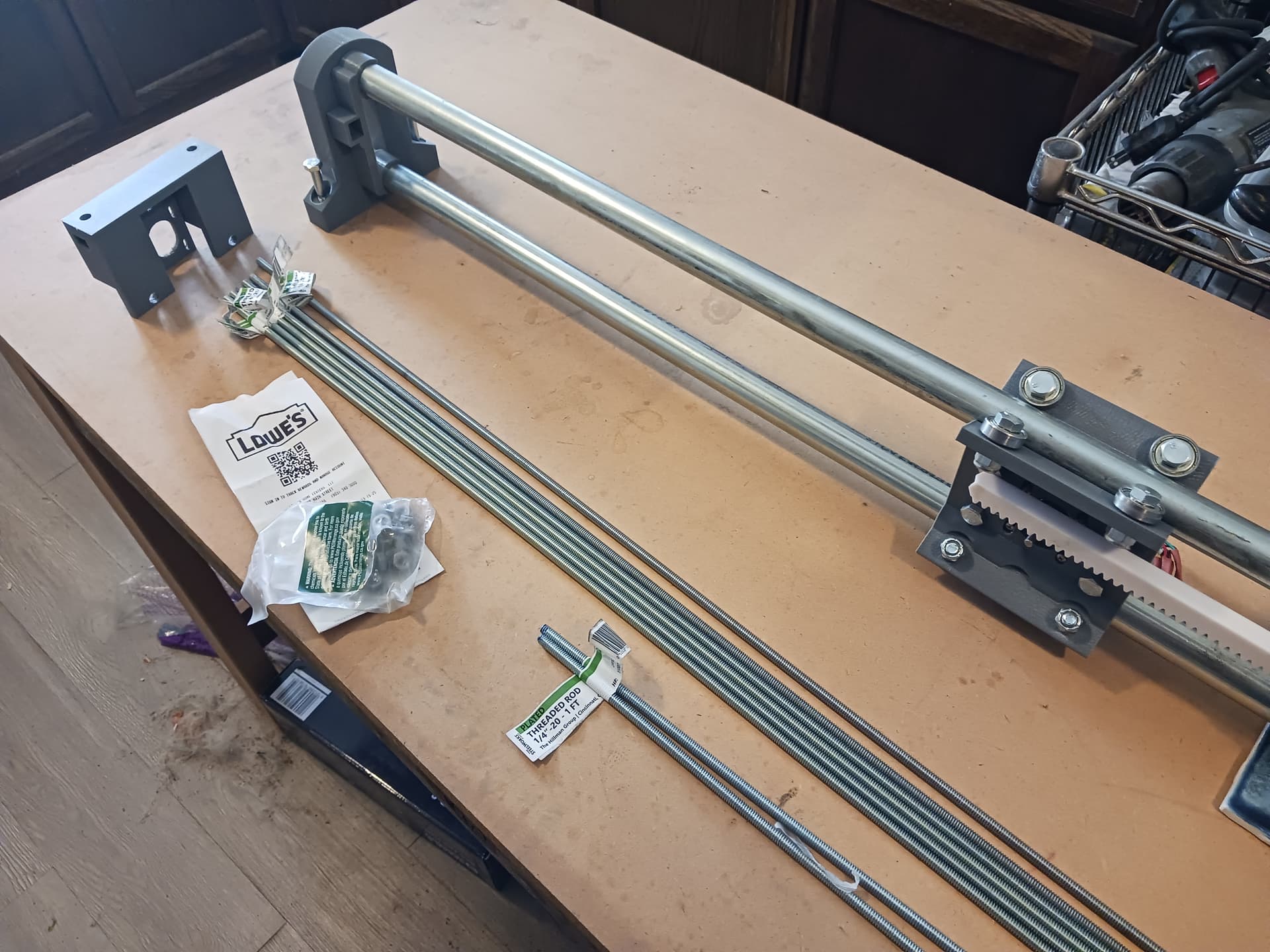
I made a quick run to Lowes to get 1/4"-20 threaded rod (the only thing so far, not from my junkbox) because with the completed racks in place I should be able to start moving stuff…
and then lightly tapped (literally) a 1’ length of the 1/4"-20 threaded rod through each of the four 40-tooth rack sections I printed a couple of days ago, to clear out any strings, debris, and roughness…
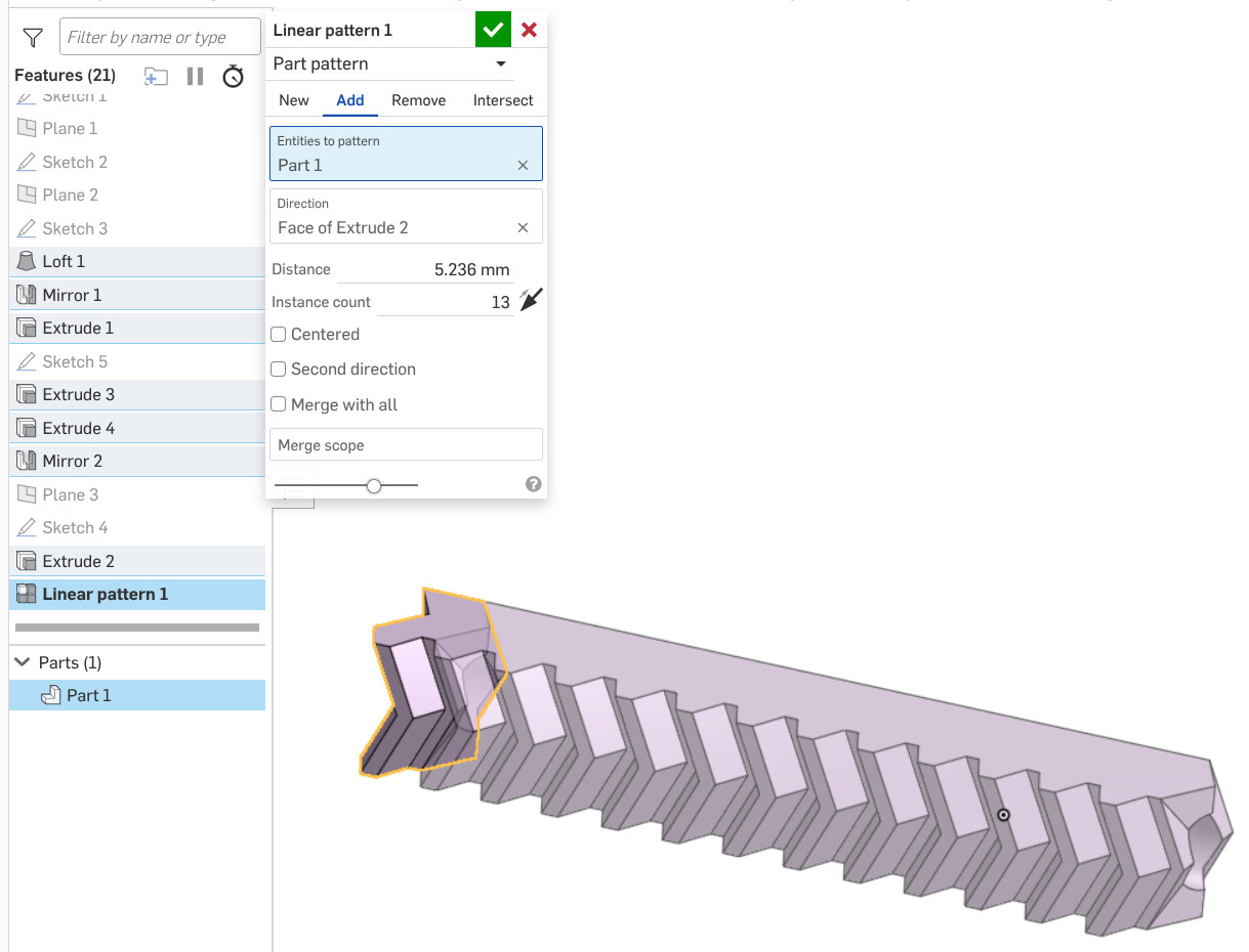
I’ve modeled a single tooth segment of the rack in Onshape and use the Linear pattern’s Instance count to give me the number of teeth I need in a segment… here just 13 teeth but up to a max of 40, which is the max I can print on my Prusa MK3S…
If this machine works out as envisioned, its size can be any size desired simply by setting the rack length as appropriate. Adjust the rack segments to fit a pre-cut length of threaded rod and you shouldn’t actually have to do any metal cutting at all. And there’s no real restriction on the conduit length either… they could be overly long and hang out on each end, even if ugly. I envision exactly this while building this silly little prototype machine. Fingers crossed…
I should have expected someone would ask me that… uh-oh!
I’m pretty sure I got the rack and pinion off Thingiverse somewhere (probably here… if so, "Thanks, @theodleif) and simply used his rack STL (not sure where I got the matching pinion STL, however) to build the Phlatprinter-inspired machine in 2017. I didn’t use Onshape then, however, and it wasn’t until 2020 when I did the R&P MPCNC that I had started using Onshape. I suspect I simply imported the STL rack mesh into Onshape and picked off the points for one tooth section. Again I’m not sure where I got the matching pinion gear… Greg’s extruder, maybe?
The Thingiverse link above however have a “customizer” (that I can’t get to work) but there’s also a SCAD file to download, called “rack_herringbone.scad”. If you are familiar with OpenSCAD I’ll bet it’ll lead you to a gear library somewhere that will answer your question.
You’ve got my curiosity flowing now, Jim. I want to play with this some more… but a print just finished and I don’t want to slow progress on my machine mock-up.
Later.
EDIT: You might want to take a look at this Github link and download “gears.scad”. Supposedly does herringbone racks and gears.
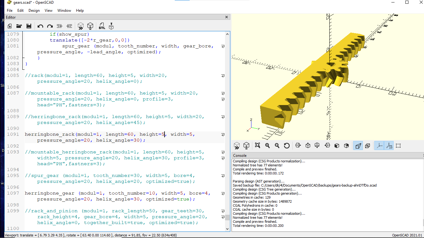
My Chromebook is running slow this morning and I can’t get Openscad to work properly. Grabbed one of my other laptops and quickly installed OpenSCAD and loaded the “gears.scad” file I downloaded from Github.
At the end of the file are commented out examples of all the different gear types… included “herringbone_rack” and “herringbone_gear”. The rack height and width need to editing and all the other parameters seem to match. Then you get the following render…
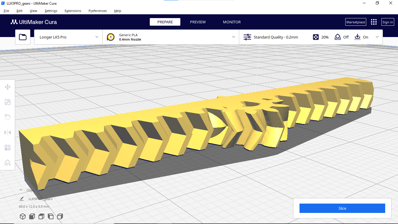
A little bit of editing and you should be able to export each part as a STL (no STEP…) that can be massaged in your favorite CAD and then printed. Here I didn’t export the parts individually but exported the STL anyway… and here’s the STL in Cura, ready to print.
dont ask me what it was, but I can remember splines like this when I was a kid and they used something like vaseline jelly for lube, so that it did not eat the splines. Now with paper you could possibly do the same thing.
If you start using a router, that would not be good at all (it would accumulate all the chips in the jelly).
First moves of the prototype gantry. To and fro ~350mm… not really calibrated yet but 160 steps/mm is pretty close… eyeballing gantry edge relative to my “calibrated” ruler on the worktable.
The rack is three 40-tooth segments with a few teeth enclosed on each end in the clip… resulting in ~600mm of exposed rack and max travel of about ~490mm end to end.