This is very cool! Could you use your existing MPCNC to mill aluminum instead of 3D printing ?
1 Like
Work?
At my age, little is required of me… so my time is my own. I’m considered “unreliable”… easily confused, too forgetful, too fragile, and too weak to do any real work.
![]()
5 Likes
Ben,
I do virtually no milling of anything… too much noise and debris. Lasers and pen plotting are more my speed… and I like to make machines for that purpose. And 3d printing fits the bill for making those machines… cheap and relatively quick.
I’m a retired EE and I can only wish I had had Onshape and a 3d printer way back when I did this stuff professionally.
![]()
– David
5 Likes
I find rack and pinion so fascinating.
Ryan, can we have that as well?? ![]()
1 Like
Me, too! That’s why I chose to do this machine… and try to use it on all three axis.
![]()
3 Likes
Still making progress…
I’m lacking only a couple of conduit clips and I should be able to start putting a Y-axis rail/tractor assembly together for fit-checks and first moves. I’ll also need to print off another plate of rack and pinion parts. I initially thought I’d orient the gantry assembly (currently too long) to fit cross-wise on the 2’ x 4’ worktable but I’m now leaning toward leaving it oriented as is and making the Y-rail/tractor assemblies be the shorter axis. I’m thinking it might be more convenient oriented that way for testing.
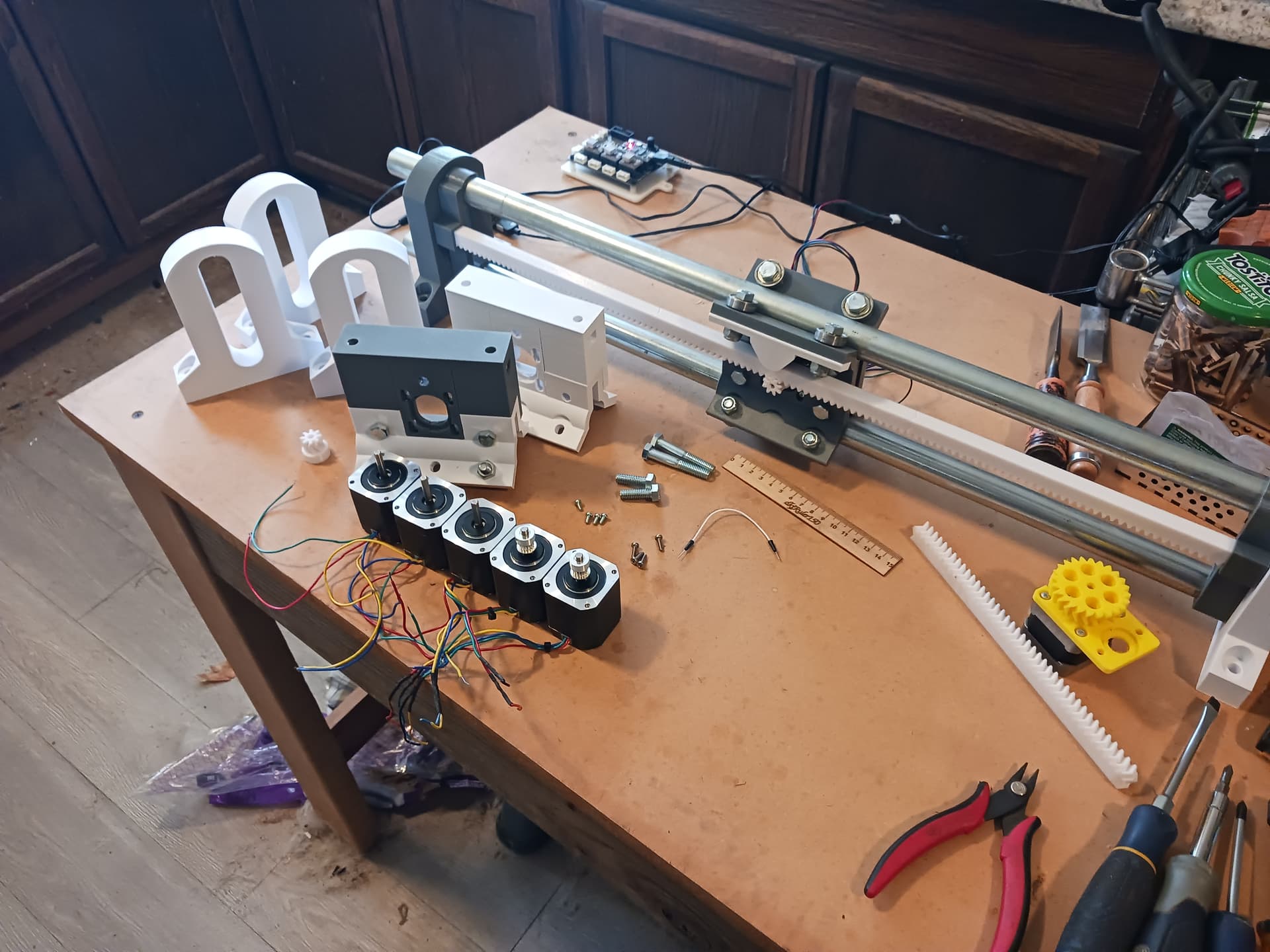
I also dug around in my stash to find a few matching stepper motors and started cleaning up the wire leads and checking their windings… only need three more steppers and should have a couple of extras, if they all check good. Sadly the leads are short and need to be extended… an operation when my shaky hands usually frustrate me most.
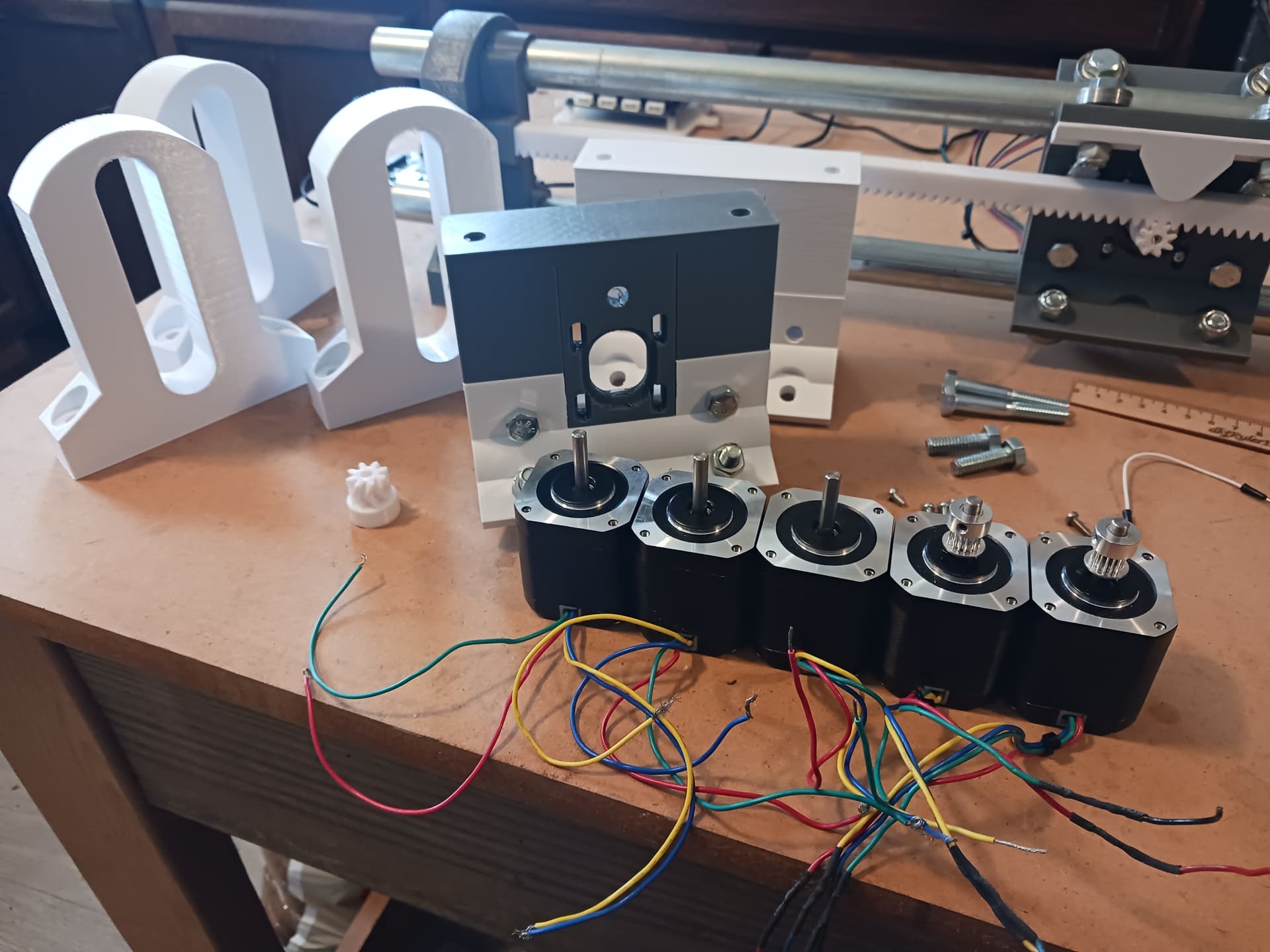
Another thing I’ve realized is that this machine, so far, is almost devoid of small screws and nuts… another shaky hands exercise in frustration that I’ve mostly avoided so far. The only small screws in the entire assembly are the 3mm screws fastening the steppers to their mounts… the rest are 5/16"(8mm) bolts/nuts and 1/4" threaded-rod and nuts for the rack assemblies. I suspect there may be some extra hardware needed to stiffen up the eventual machine but for the moment everything just slides together and/or clips tightly in place… IMO it would be nice if it could remain that way. ![]()
Need to make a quick grocery run. The conduit clips that terminate the rack ends should be about finished when I get back…
Later.
3 Likes
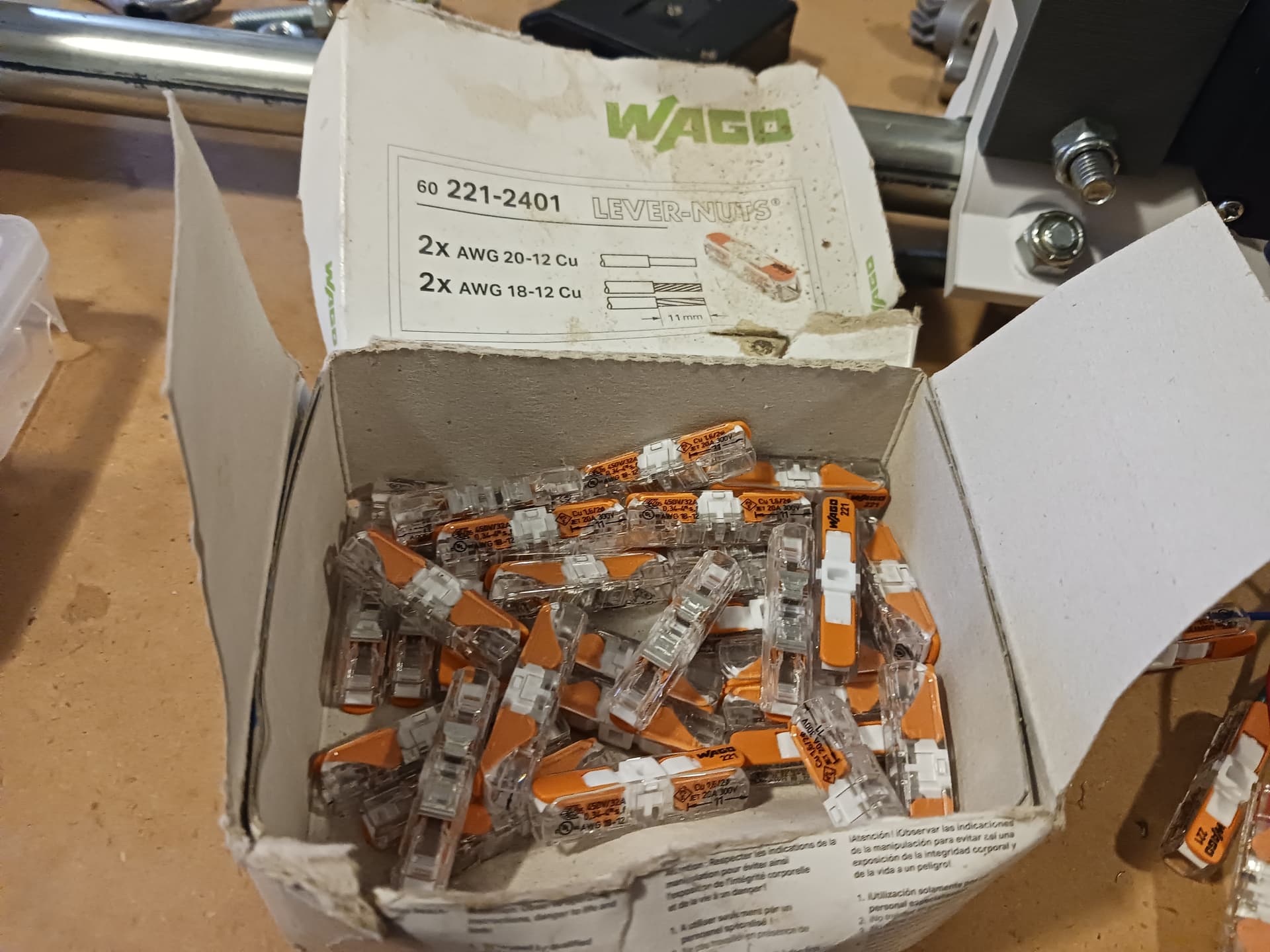
Have any wire lever terminals? Perfect way to do stepper wire extensions, no solder, no crimp needed.
You can find these kind at the internet bookseller:
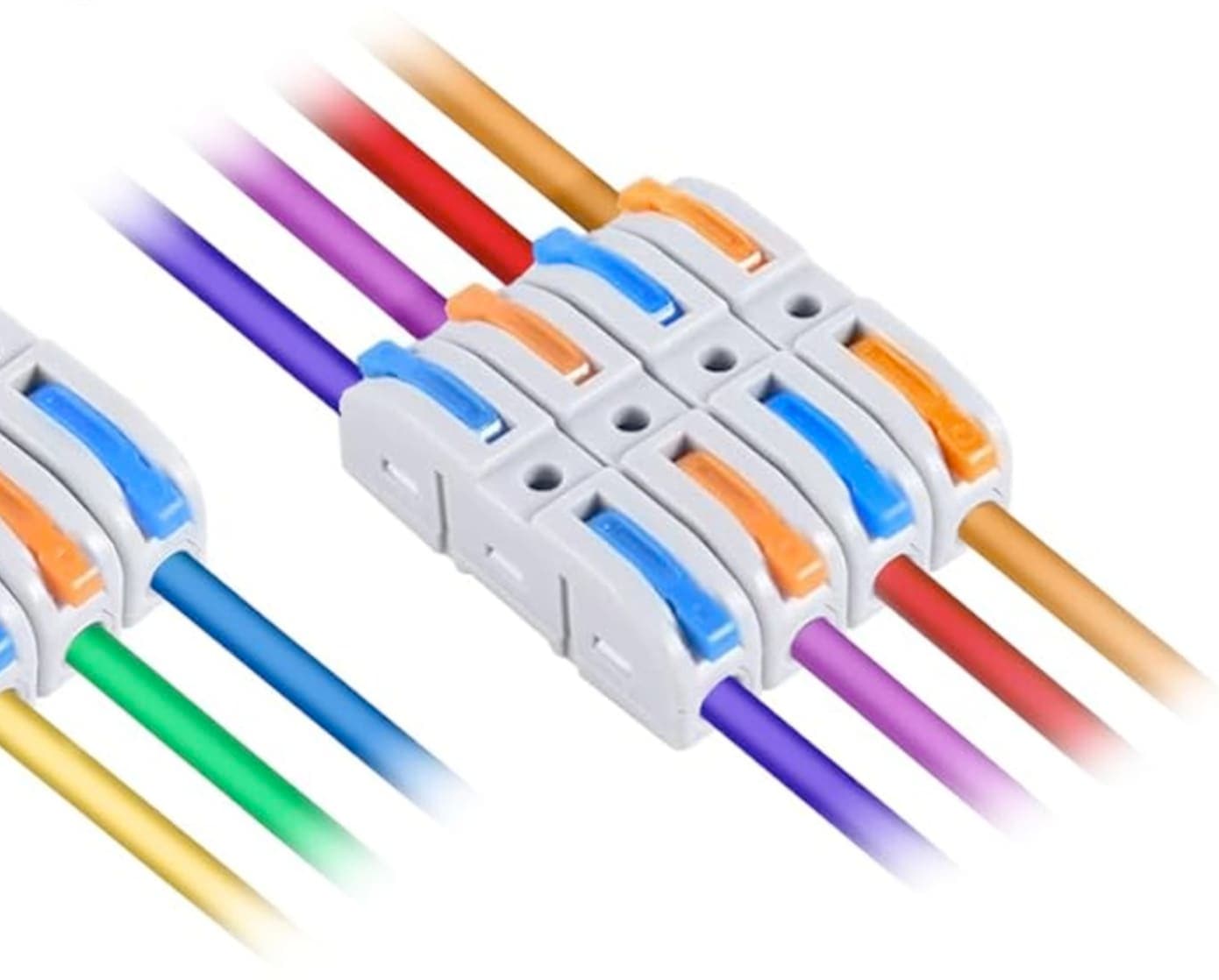
And these kind at the Orange big box home improvement store:
1 Like
Thanks, Jim, for the tip! I’ve used small gray wire nuts before but these would be fantastic! I’ve also used Wago’s before in a remodel of my great-grandmother’s little house… into an apartment for my grand-daughter. I’ll check with my SIL to see if he has any of those left over. Never thought of using them on smaller wiring. I was dreading soldering the connections. Thanks, again! ![]()
1 Like
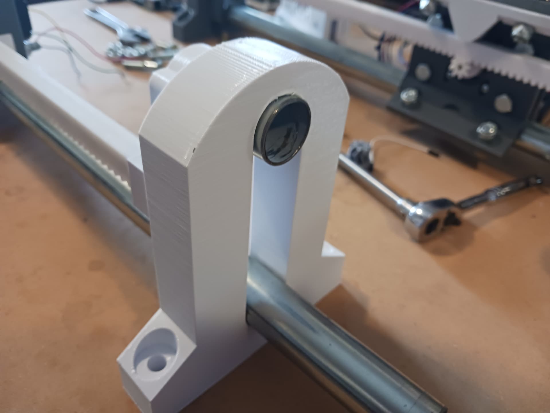
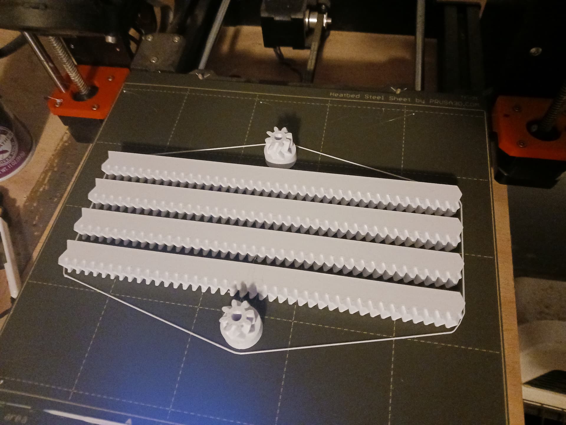
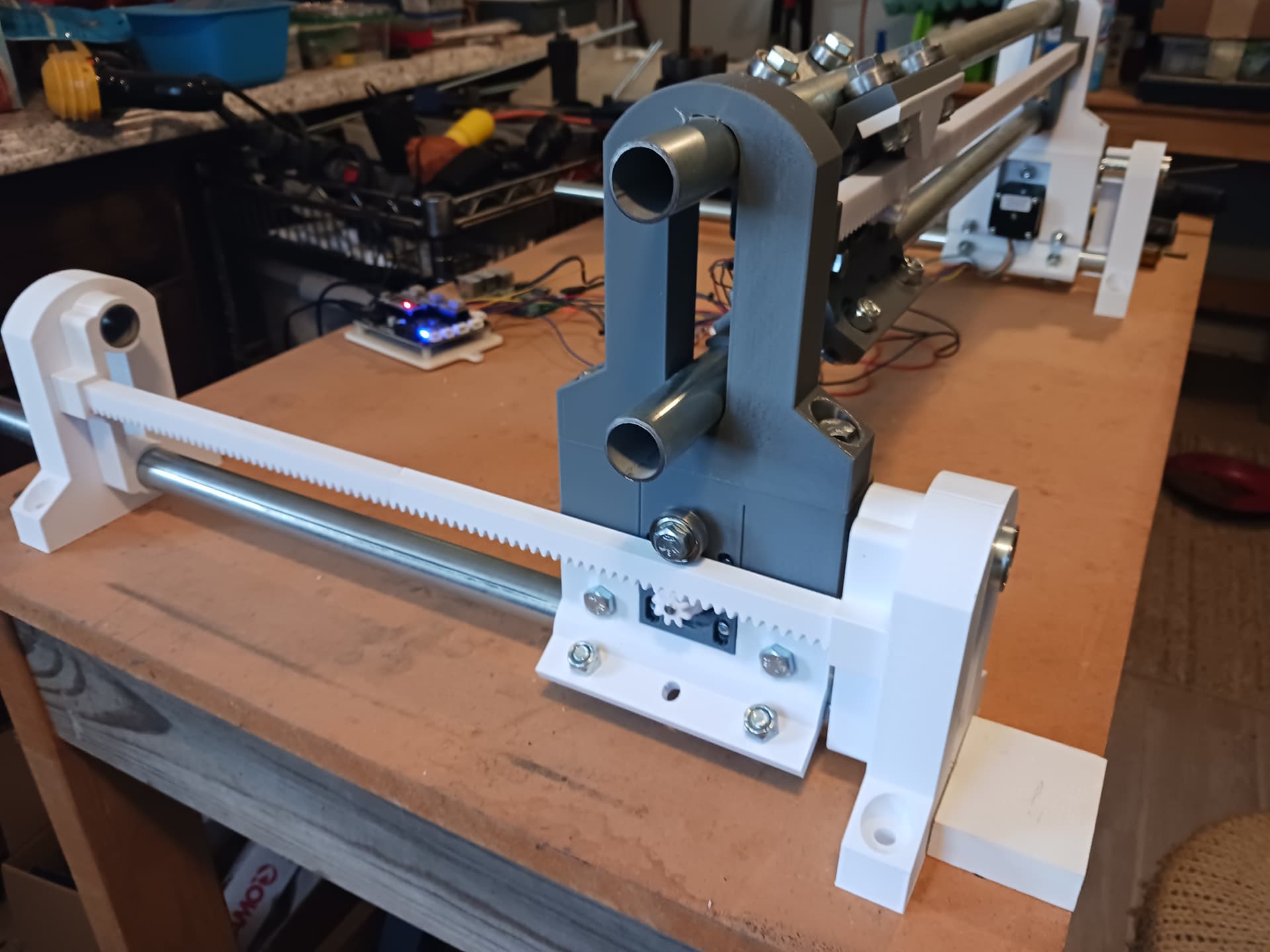
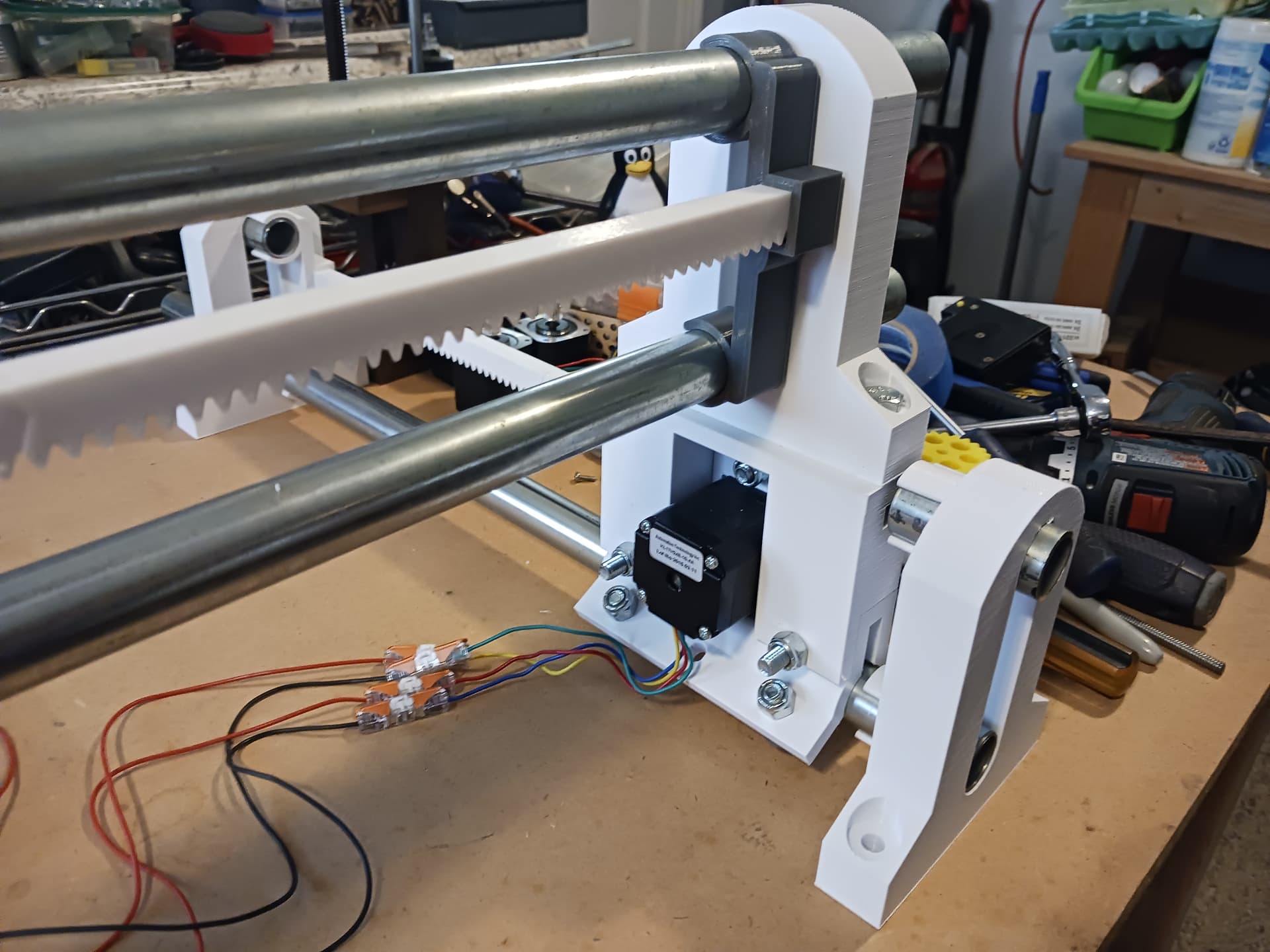
Finished printing enough parts to build up and fit-check one of the lower axis…
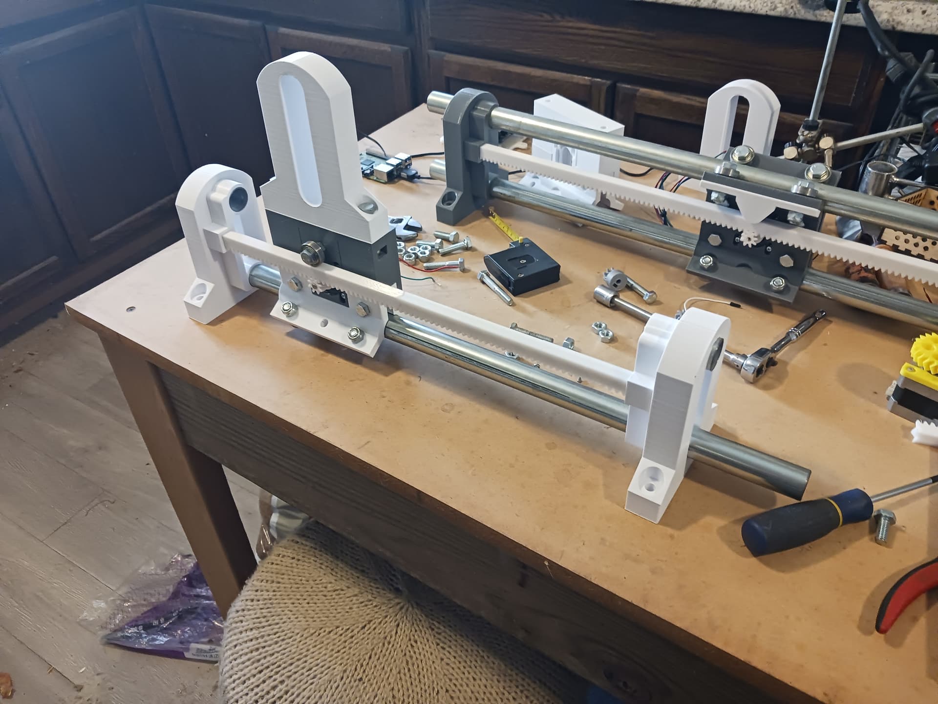
The ends with the short conduit stub in the upper position… to keep things upright and in alignment.
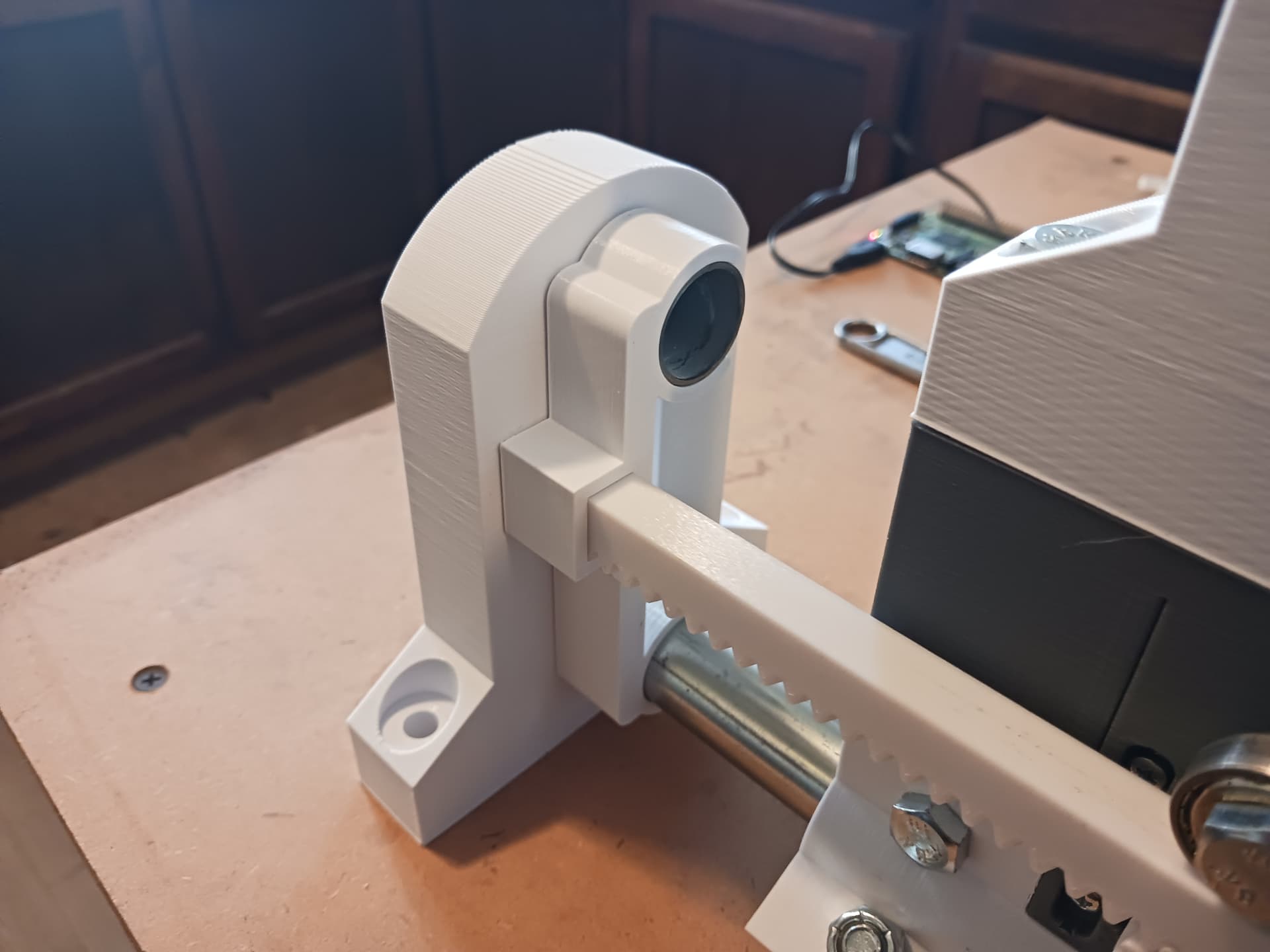
The gantry ends will of course be fitted into the slotted support bolted to the tractor assembly…
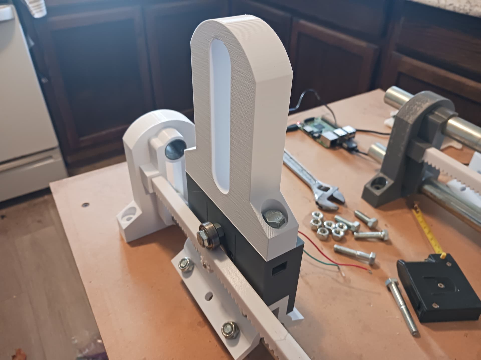
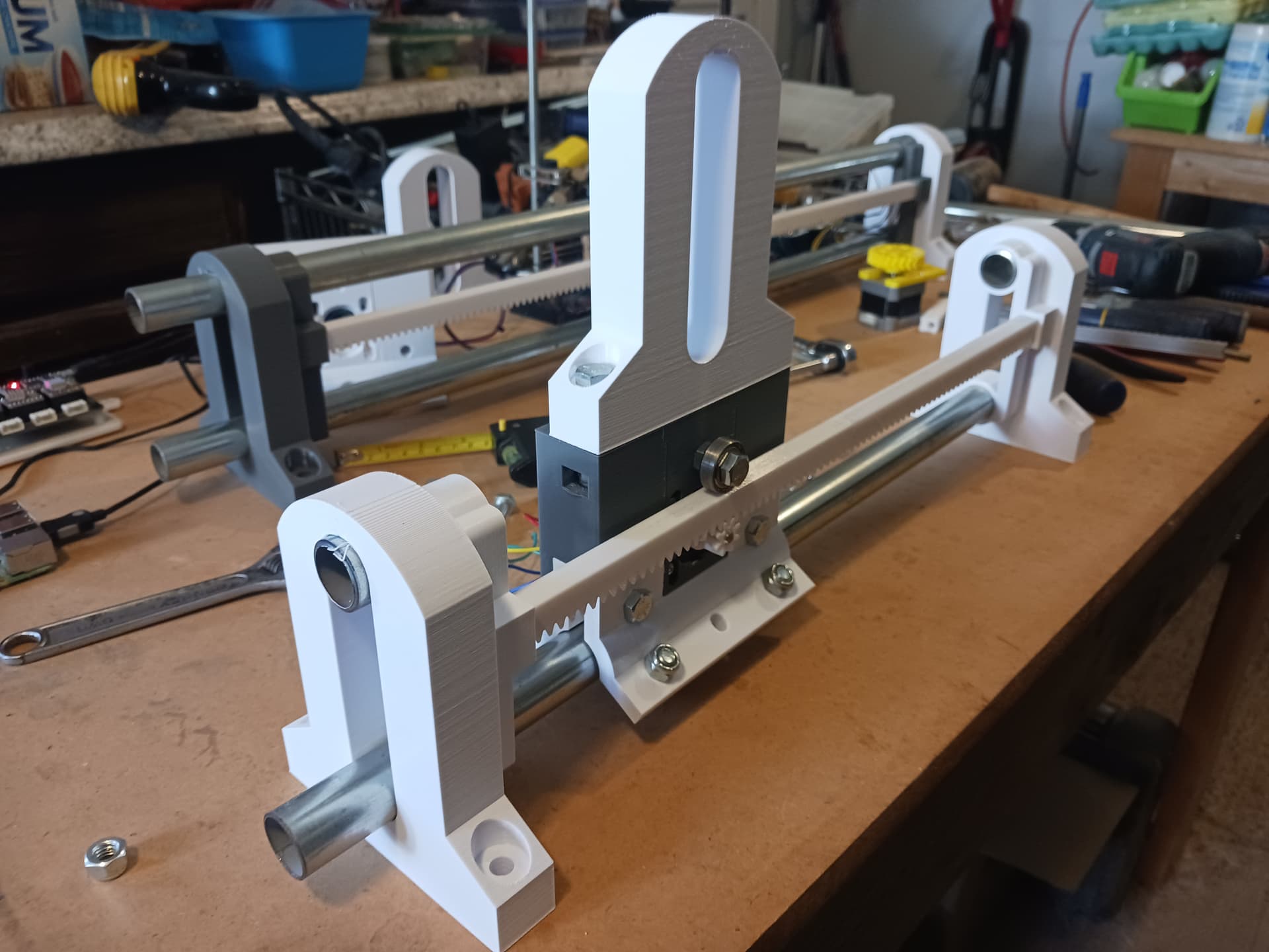
and finally the rack and pinion gear with the pressure bearing in place.
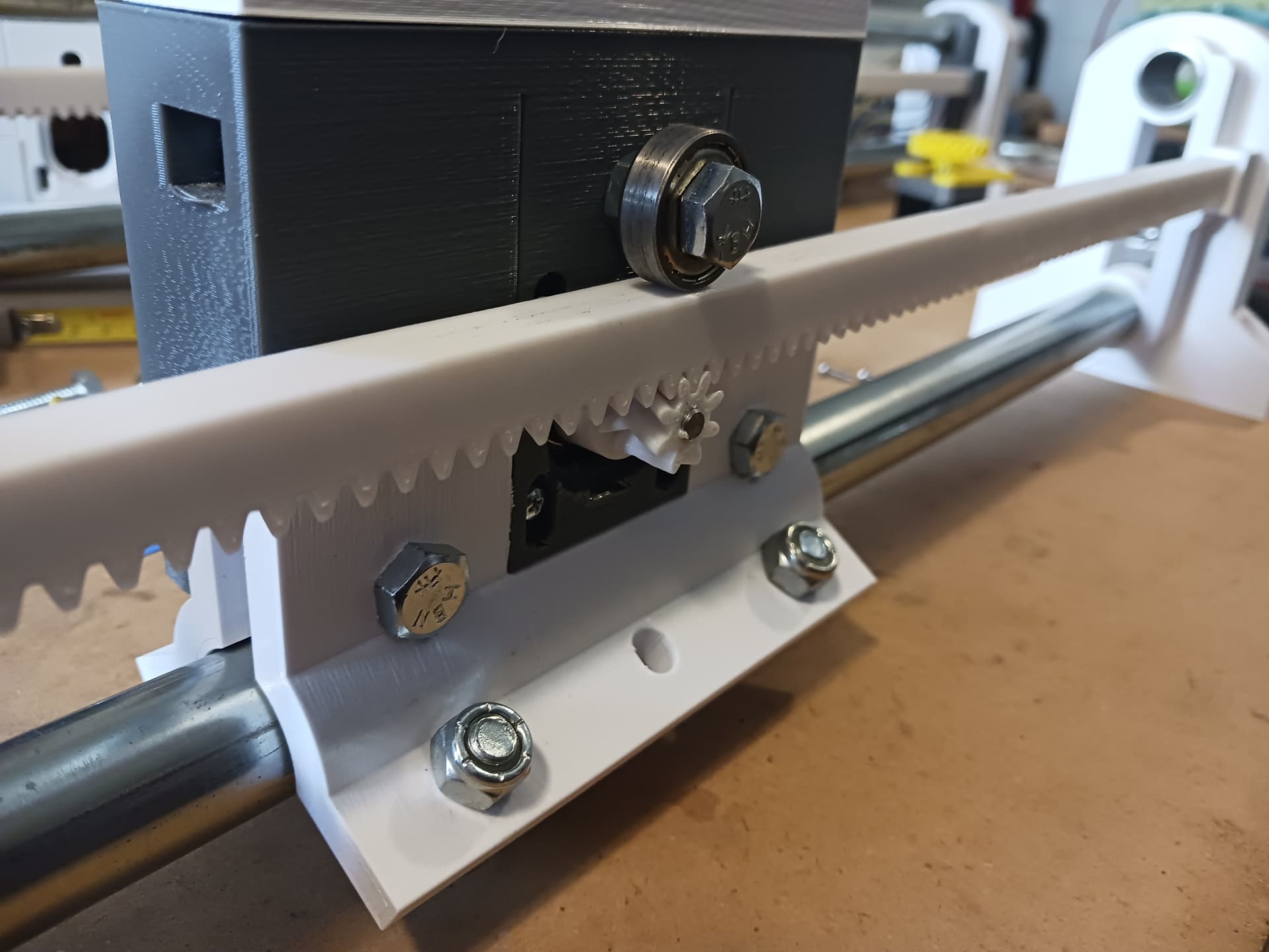
Everything looks reasonable and should be ready to start seeing if I can move it… once I get the motor wires extended, of course! SIL says Lowes has those Wago-style connectors… may need to make a dash to get them. Yuck… I hate driving! ![]()
– David
3 Likes
Woo hoo! Looking forward to seeing it moving.
1 Like
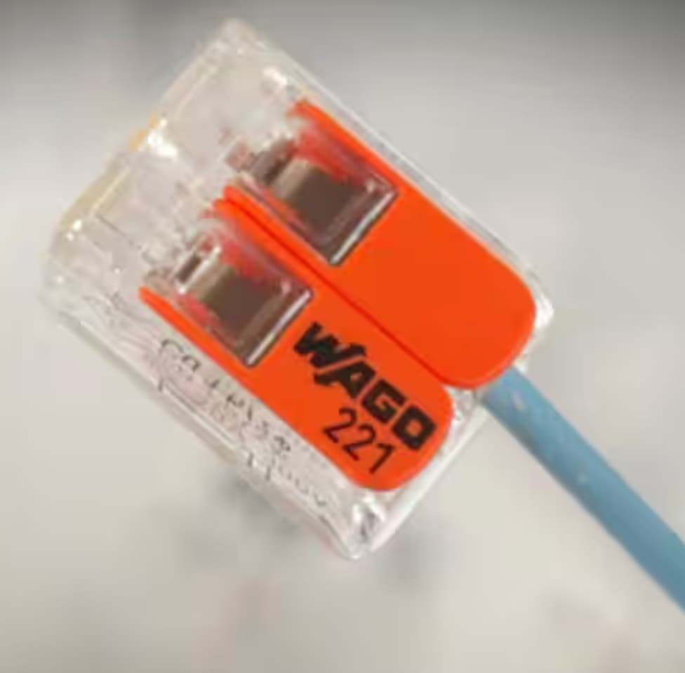
Lookee here!
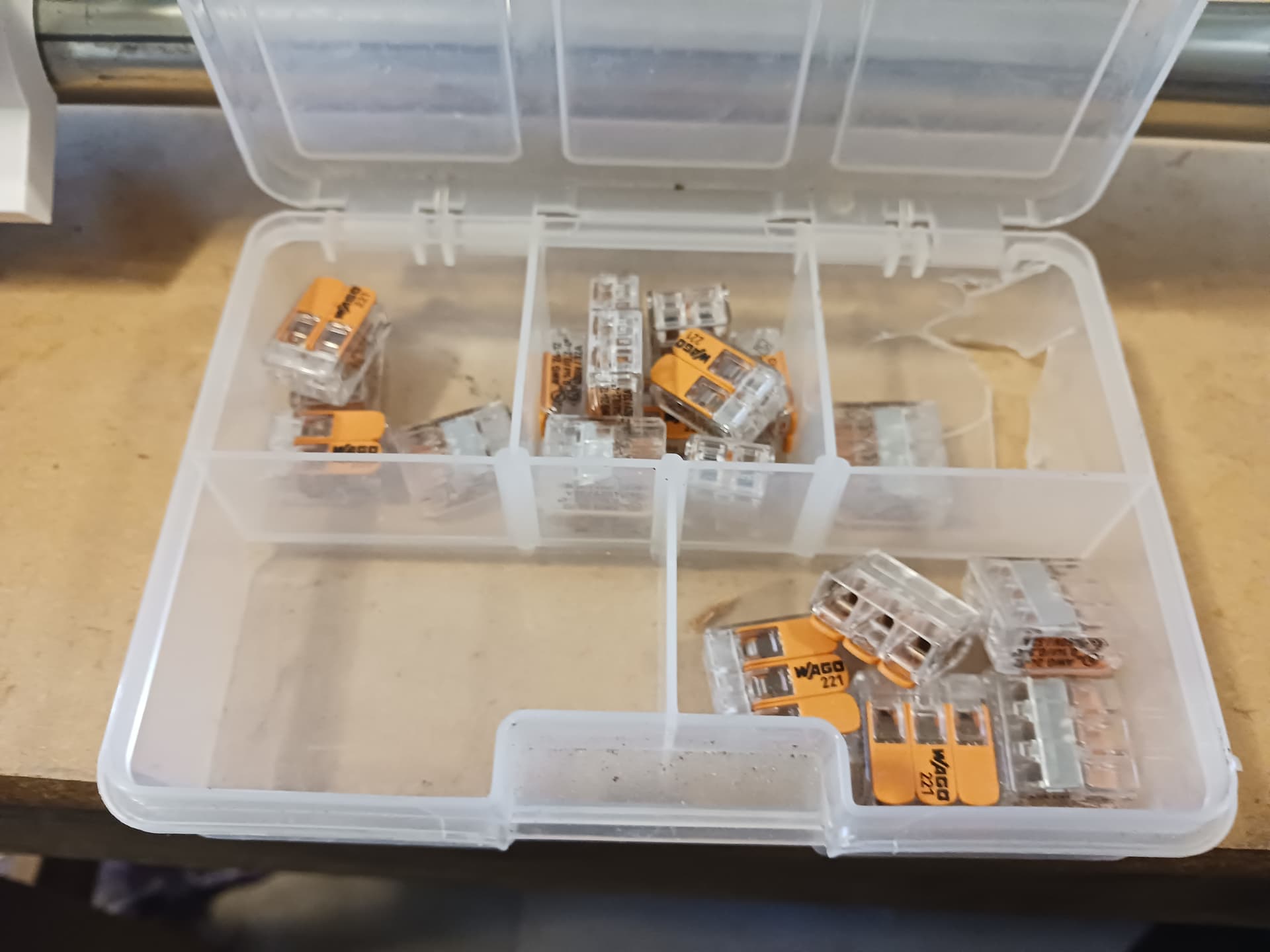
SIL had these left over after the renovation. I had actually bought these before we started to see if we might like to use them on all the wiring for that project. We actually bought a similar item from Lowes as we needed more than just this little kit of Wago’s. But since I purchased them and they found their way into SIL’s junkbox and now into mine… I’m counting them as junkbox items!!!
I may still go ahead and order some of those first connectors you showed in your post. I like the straight-through look of them…
I need to eat something before I go try to start moving things under power. I’ve been losing weight (I’m actually dieting… down to 222 lbs. from 255!) but had stagnated at about 228 lbs… until I started this machine build! I’ve been enjoying myself so much I haven’t wanted to stop to eat…
![]()
1 Like
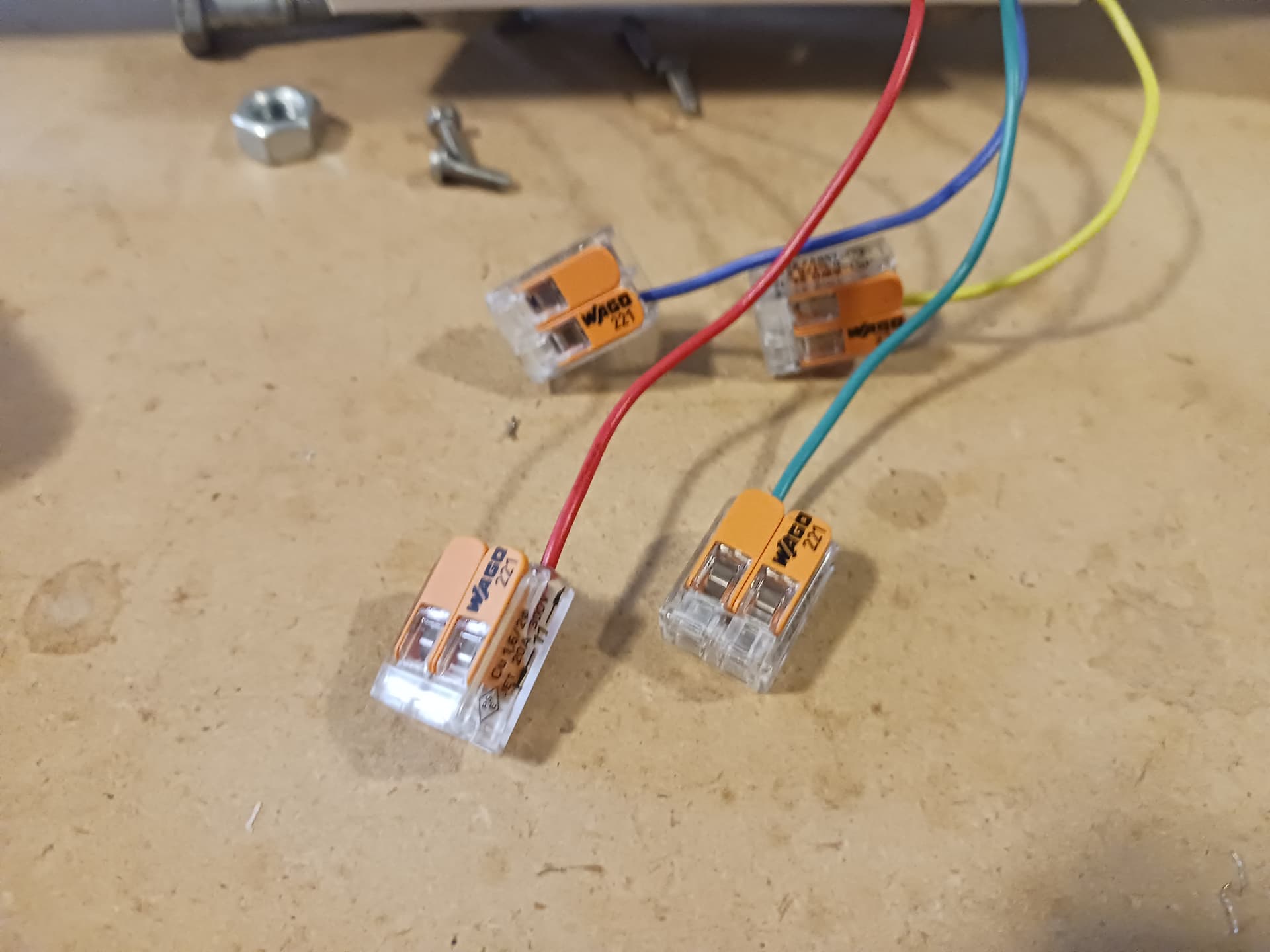
Found I also had gotten some in-line Wago’s so connected the motor wires to a suitable connector. They, too, were in my junkbox… so they count!
And they work a champ…

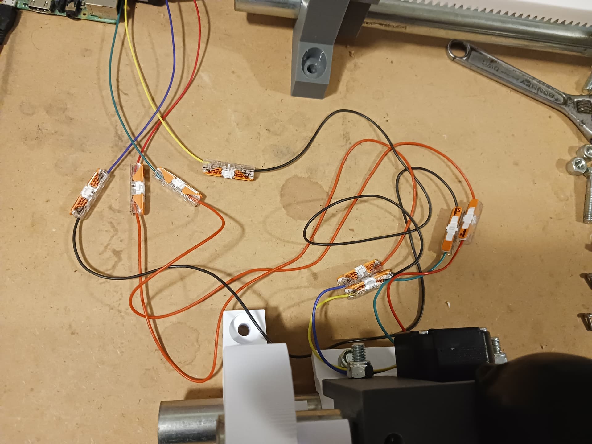
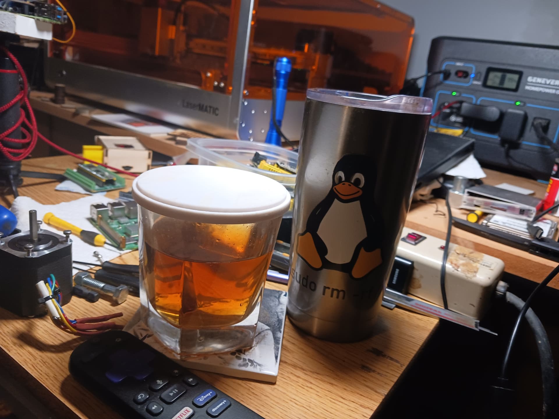
Time to celebrate with all my friends…
I’ll try to duplicate and check out the other axis next and add the gantry to its rightful place. And then I need to get after the Z-axis so that I can plot the obligatory crown.
![]()
Later.
7 Likes
Haven’t had a drop of the spirits since 2017, but gonna have some a sparkling water and OJ in celebration right now!
Woo hoo!
4 Likes
Looking great!
And seeing it move reminds me that I still want to build a slider for time lapse photos one of these days. Since I have a box of original MPCNC trucks sitting here…maybe I can cobble something together when my current projects are done…
1 Like
Thanks, Jason!
That’s how I built my camera slider… using my junkbox and 3d-printer. I used an old TV IR remote and captured the button codes to write the Arduino code to first “program” and then run the slider…
https://www.youtube.com/watch?v=iHw4fDvjaLw
Here’s my favorite test of the slider I made…

You might want to check with Jeff (@jeffeb3) as well… he made a much more refined slider (for his father IIRC) and took some nice time lapse of his snow-covered back yard.
I woke up this morning and found I had dodged a bullet…
I left a plate of rack and pinion parts printing – a 6-hour print – and went on to bed thinking I still had plenty of filament on that new roll of Inland PLA+…
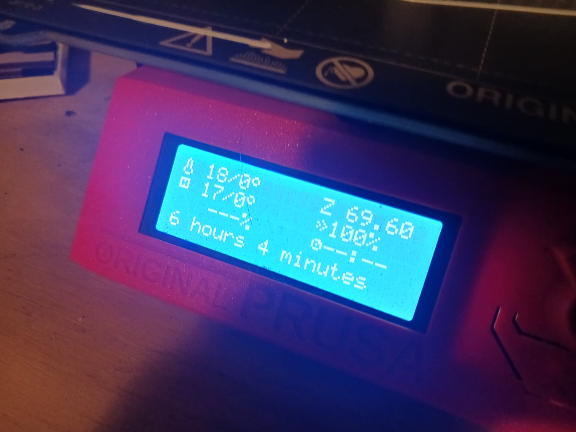
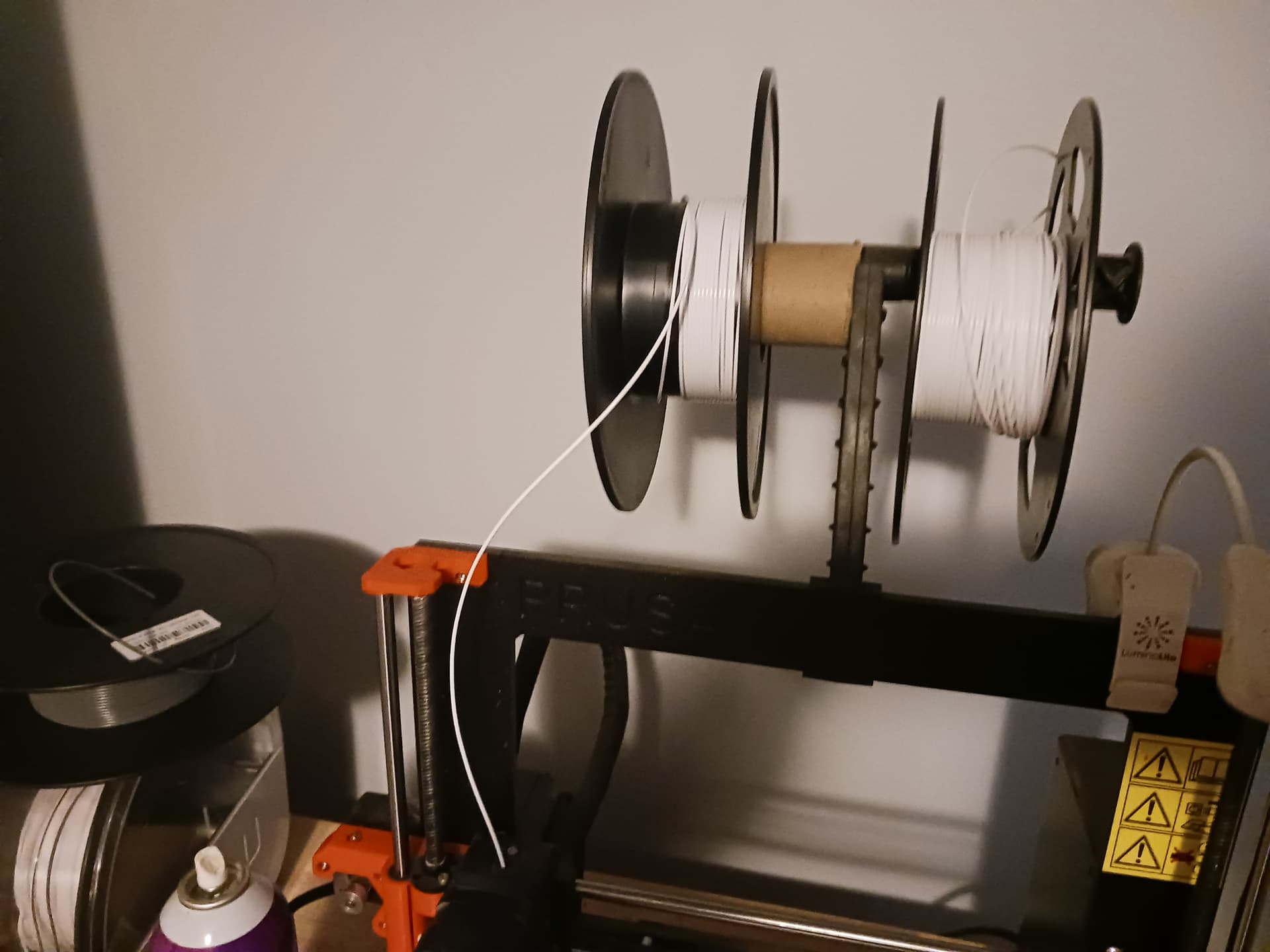
only to discover that only half of the last layer is left on the roll. A pretty close call and pretty much a record for how fast I’ve used up a full 1-kg roll of filament… just 2 days.
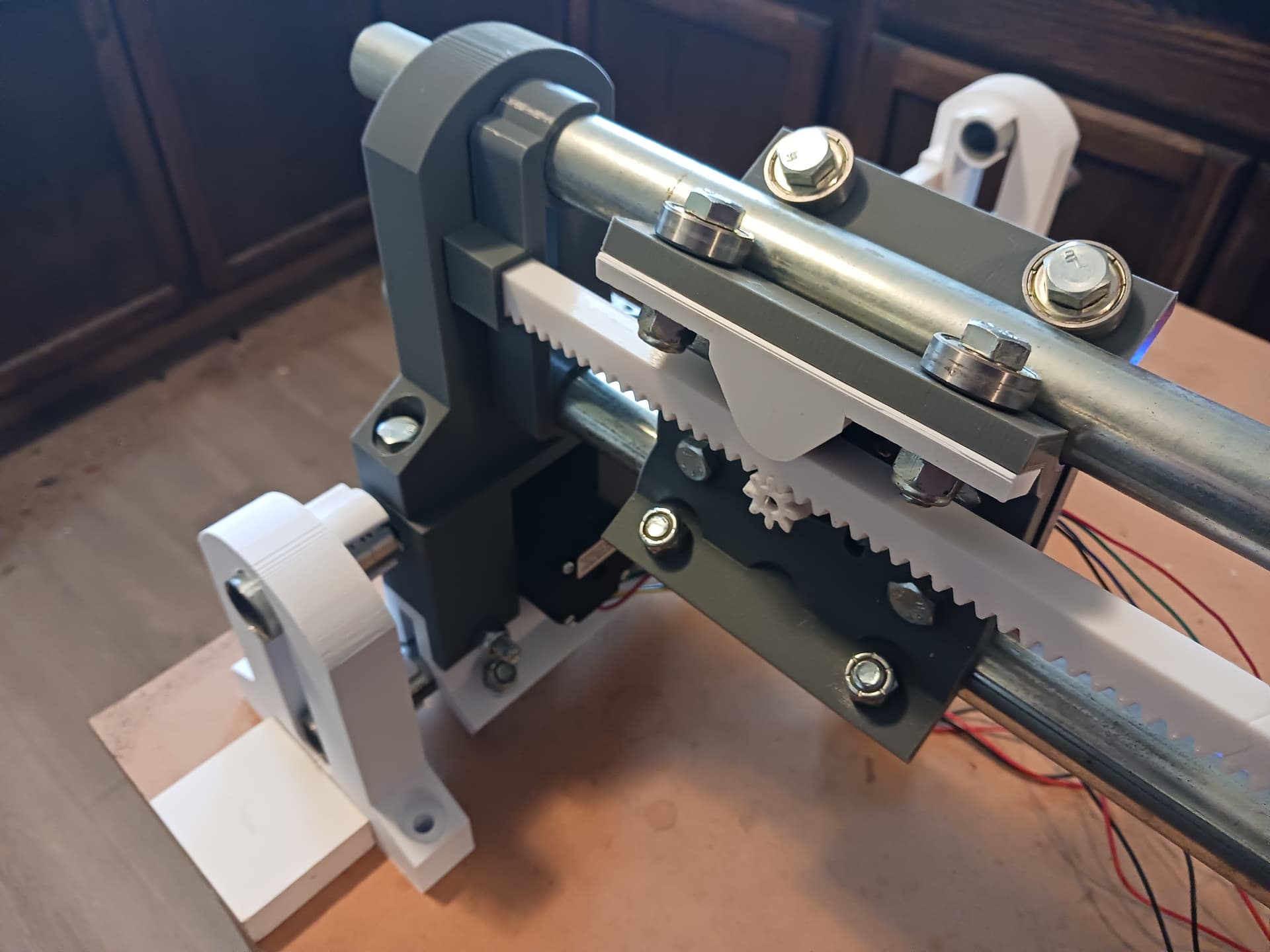
But it did successfully complete and I now have enough parts to assemble the second Y-rail/tractor axis…
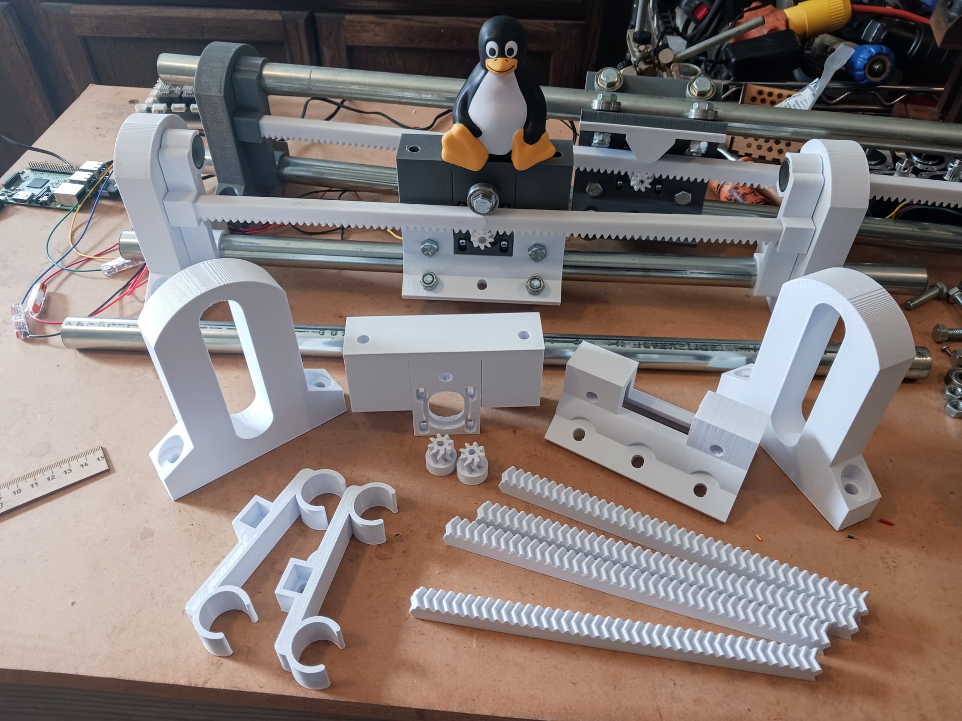
I think I’ve got all the long-ish prints done and it should just be assembly of the X-Y machine I envisioned in post #7 now. Then it’s time to get serious about the Z-axis…
![]()
Later.
1 Like
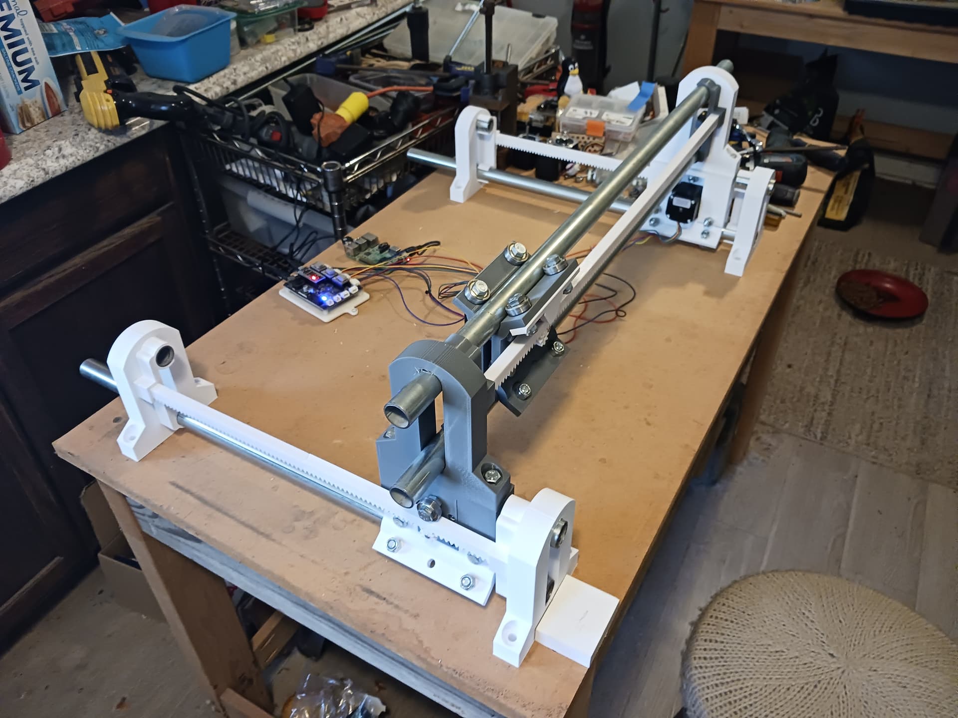
Good progress this morning…
Got the Y-axis completed and checked out. So started stacking the X-Y machine. What can I call this thing… any suggestions? Though it’s “mostly printed”… oddly it seems MPCNC is already taken! ![]()
![]()
![]()
![]()
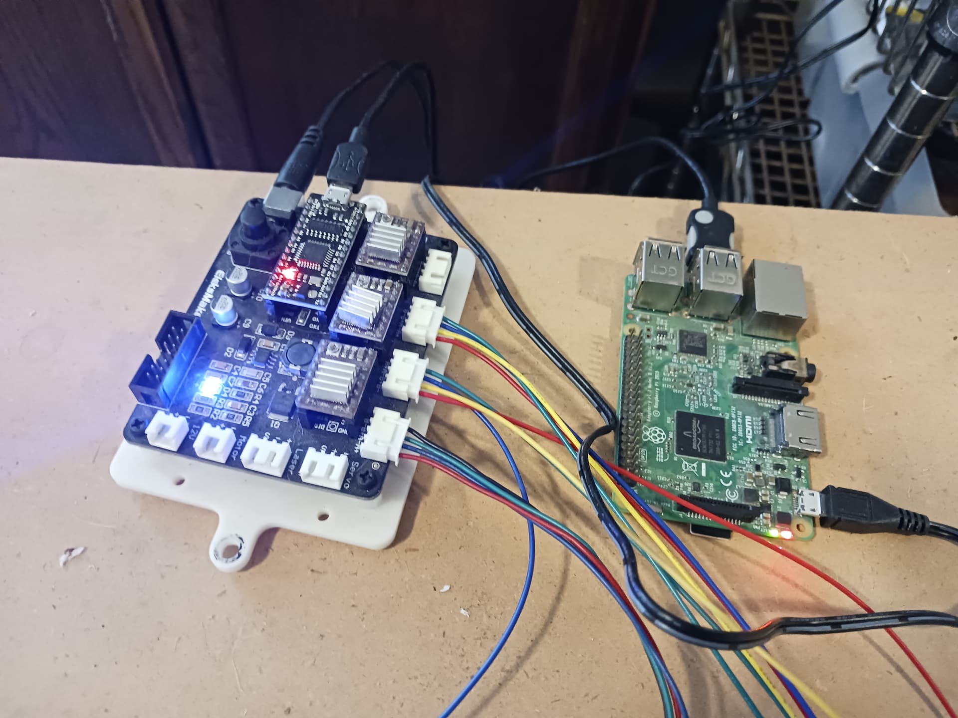
![]()
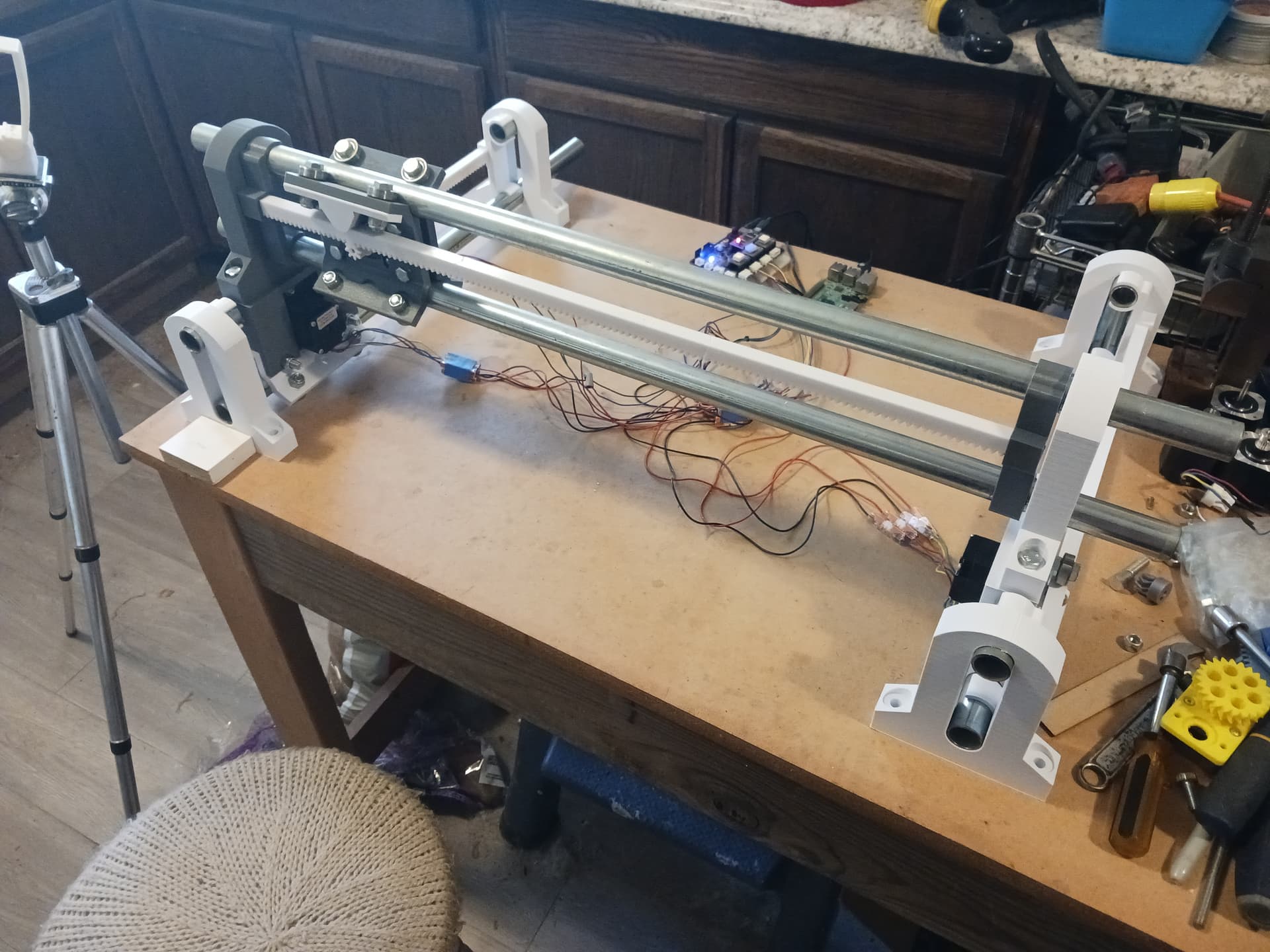
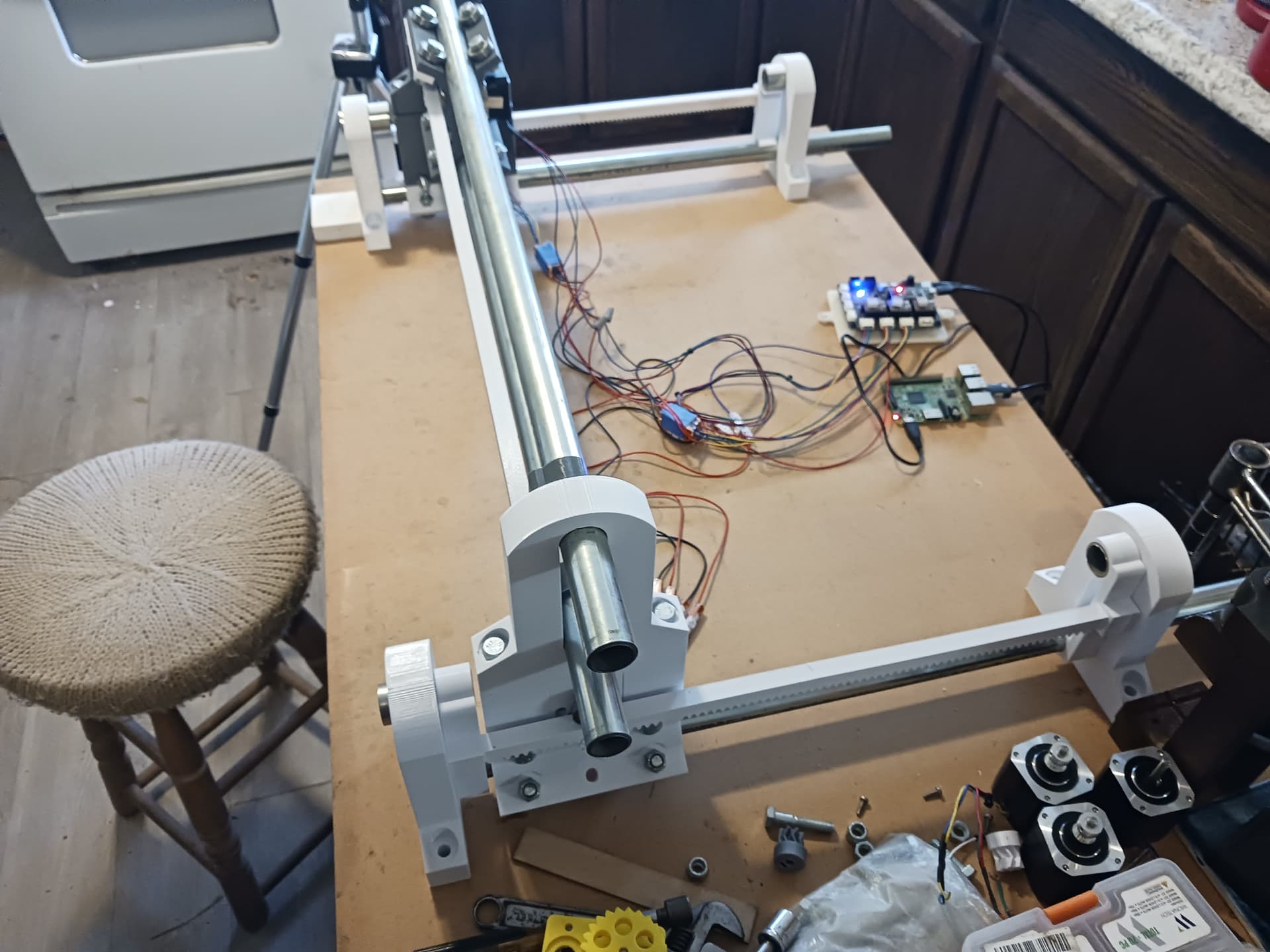
Wifi control using Jeff’s V1Pi/CNC.js running on a Raspberry Pi 3B+ and an Arduino Nano-based 3-axis control board. Those Wago lever-connectors were a life-saver, @MakerJim!!! Thanks, again!
More photos of the stacked tractor/gantry assemblies…
A couple of test runs…


I think now I should calibrate each axis and air-mill a figure or two to see all three axis in motion all at once. Then I’ll need to start thinking of how to strap a laser or Z-axis to this… erm… uh… uhm… “mostly-printed thing”?
Later.
– David
5 Likes
Wait, what? Already?
Your work rate is unbelievable!
2 Likes
MPR&P
1 Like
Wouldn’t it more like MPR&PCNC?
![]()
2 Likes