Printed R&P X/Y/Z Platform from MPCNC junkbox

I’ve also thought of using the 1/4" threaded rod to lock the clips and slotted supports… if they were made long enough to go through. I just got tired of printing (I’m using just one printer…) the slotted supports at ~8 hours each and I felt it was good enough for pen or laser. I agree… adding through-holes that would be the proper thing to do.

I printed the “clamshell” parts on end… without any support except for some support “vanes” I added manually in the large motor cutout. The bearing bosses are 45 degree chamfered and print fine without support…

Other screenshots to show how I oriented the parts on the build plate in PrusaSlicer. The many Z-parts on the first screenshot can all be printed without support except the tall Z-motor and bearing mount… for it I used “support from build-plate only”. Also the pressure-bearing “pin” (right-most screenshot) used “support from build-plate only”. Most everything else is printed with no support.

I’ve got a blank tool plate idea (longer wider clips ) for the Z-axis… just haven’t cut the conduit to proper length and printed it yet. I just got lazy once I had something that mostly worked…

Oh I see that now up thread. Can you export your part with support vanes as a .3mf? Those will go on a printer as soon as I have pushed the carriage supports through the system.

Though maybe with a brim the clamshell parts would be a good candidate to throw on the TAZ. I have some ancient 2.85mm PLA filament (in your signiature white :smile: ) that I’ve been wanting to chew through

Check this out and see if you can use it…

V5-MPR&P-parts.3mf.zip (1.4 MB)

1 Like

Did you design the rack yourself or did you download the design some where. I am interested in using this on a build i have envisioned. Probably will 3D print with blue wax and investment cast out of aluminum.

2 Likes

That’s discussed a bit up-thread. I’m curious about your aplication- the PLA parts I have in my hand are plenty strong for anything an MPCNC would get pressed into service for.

There are metal versions of modular rack available- it’s been a while since I looked into it, but herringbone rack and pinion is a comon thing.

1 Like

I put this in a DM but not sure you saw it…

As you might be wanting to give the MPR&P a specific “footprint” to fit on a tool cart, there is another tab in my Onshape document that will be helpful… “Adjustable_rack-v2”. In the “feature tree” along the left side, scroll down to the last feature, “Linear pattern 1”, and double-click. In the popup dialog, change the “Instance count” to the number of teeth you want in your rack segment. Then select “Part 1” in the Parts list below the Feature tree and right-click… “Export” the part as STL.

On my Prusa MK3S, I’m limited by the bed size to 40 teeth. On MPR&P, a total of 100 teeth gives a Y-axis linear stage footprint (length) of about 23.5"… and a working length of ~15". For two 40’s and a 20-tooth segment making up the 100 tooth rack on MPR&P… the 1/4" threaded rod through the middle of the rack segments is cut to 21-1/8".

1 Like

Looking at it now.

Turns out I burned through most of my old 2.85 PLA printing LR4 beta cores. There’s MAYBE enough left on the spool which is on the printer. I’m going to chance it. The roll sitting on the bed is black, so I may have one white pair and the rest in black. That’s fine. Machine will be a mix of V1 black and red, plus DKJ white.

and printing:

1 Like

Always interesting days when the print farm is running.

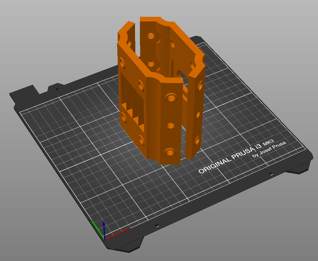
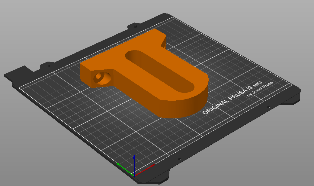
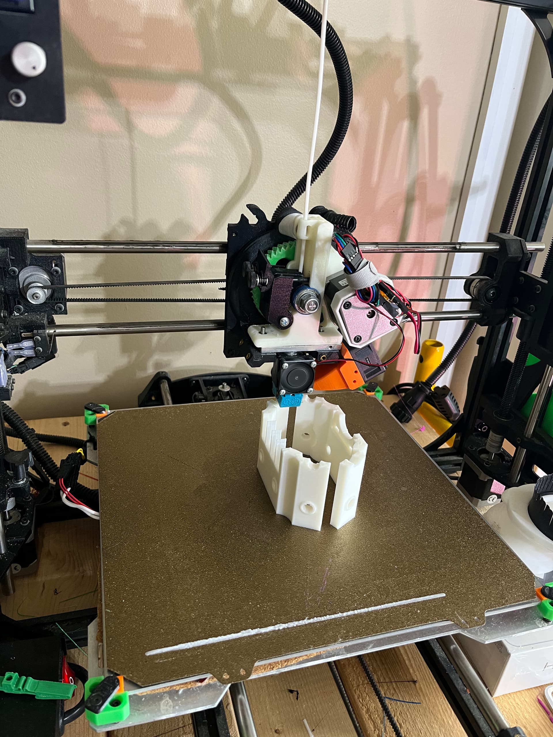
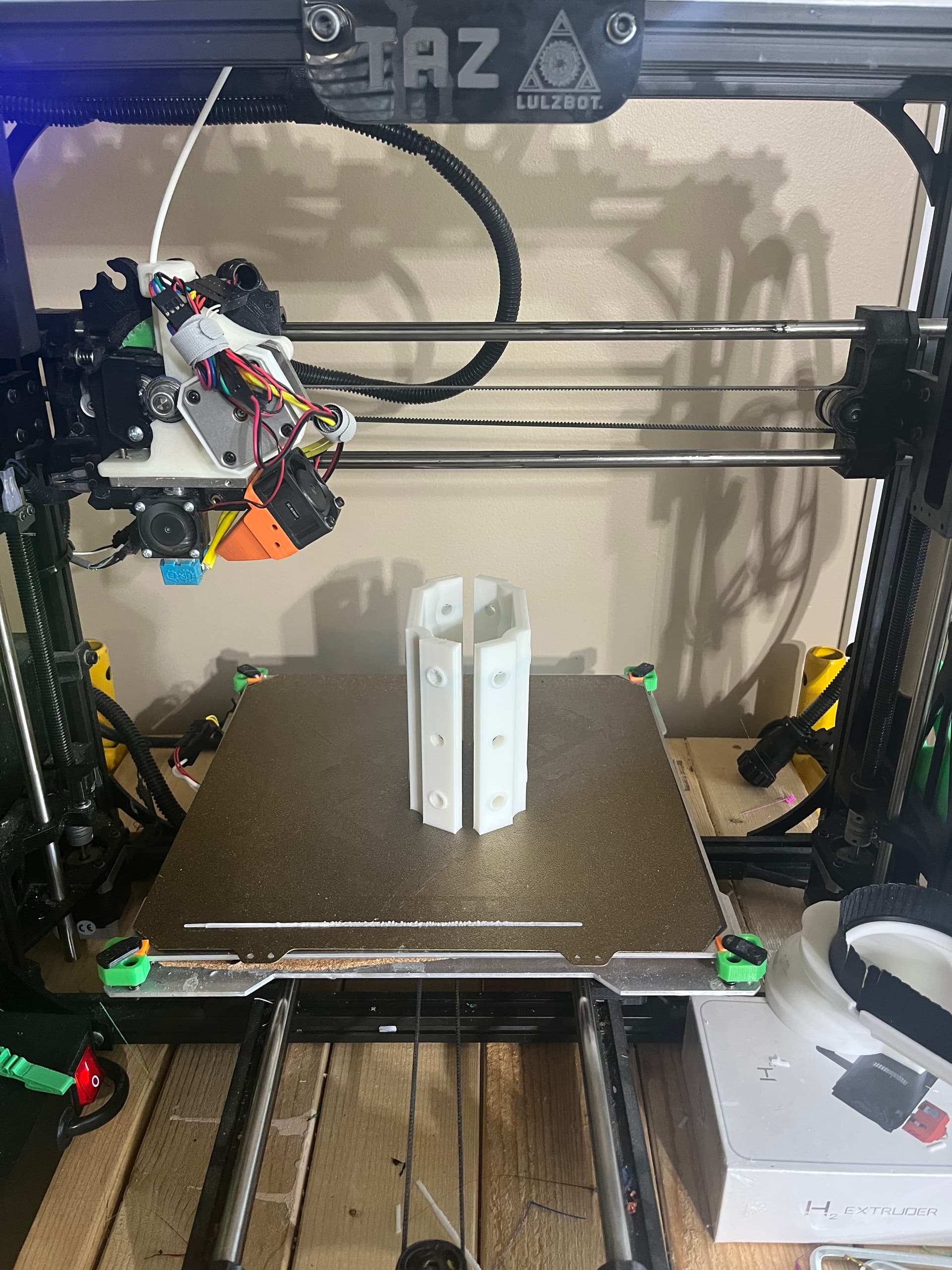
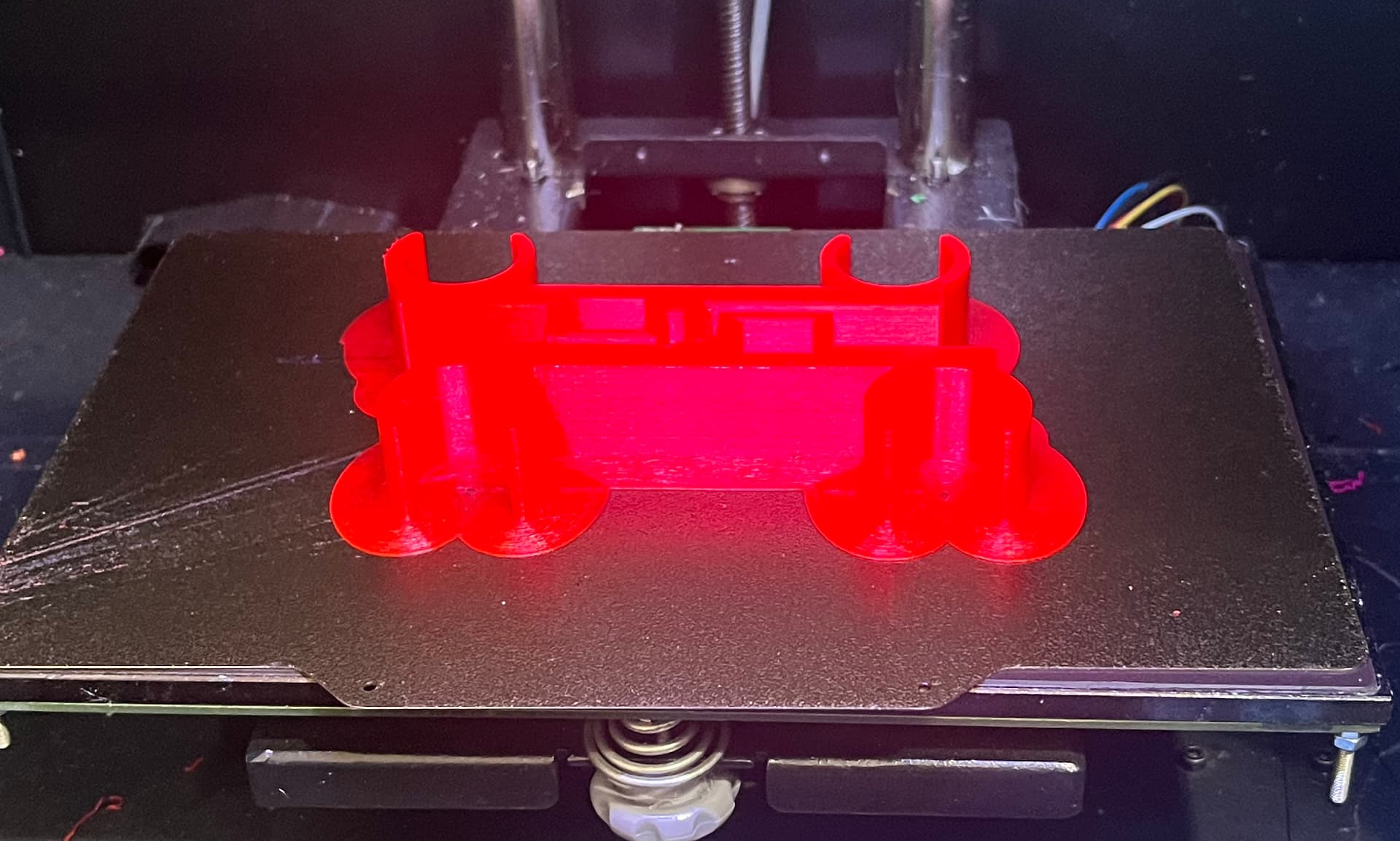
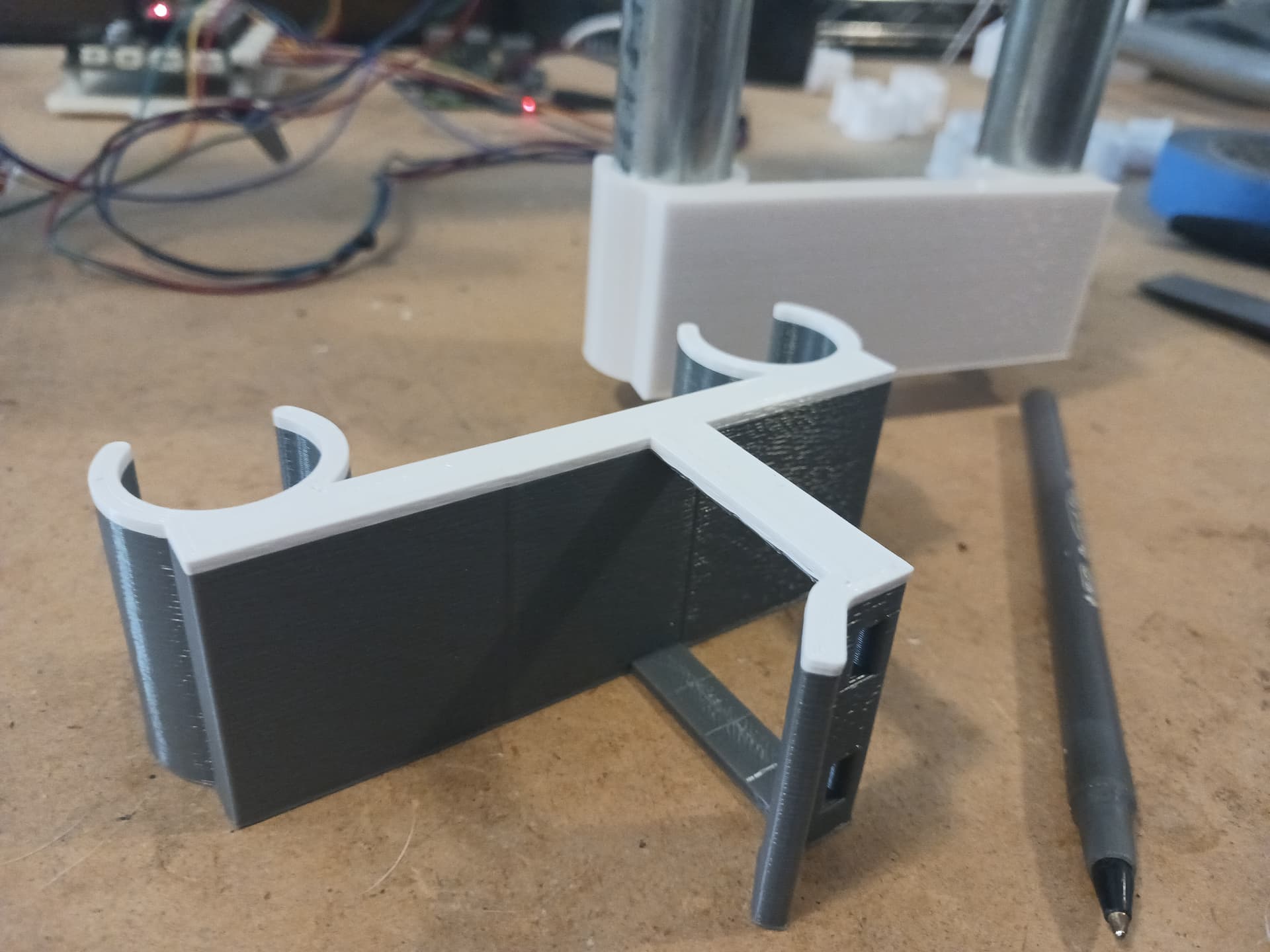
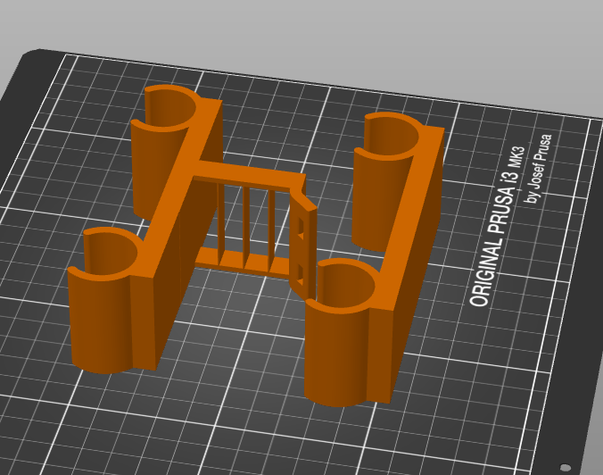
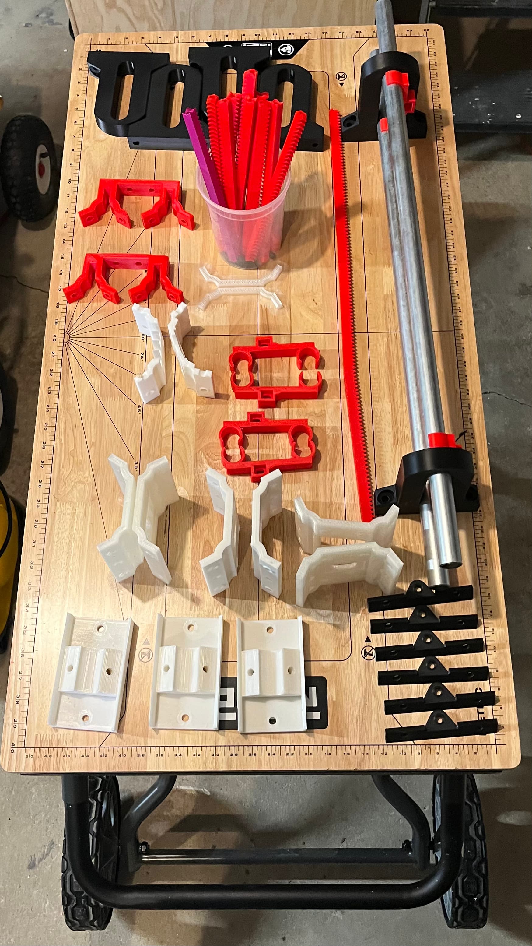
The A5M spit out carriage supports like clockwork. Printed 6 of these, using nearly an entire spool of re-PET that I had laying around. More found materials.

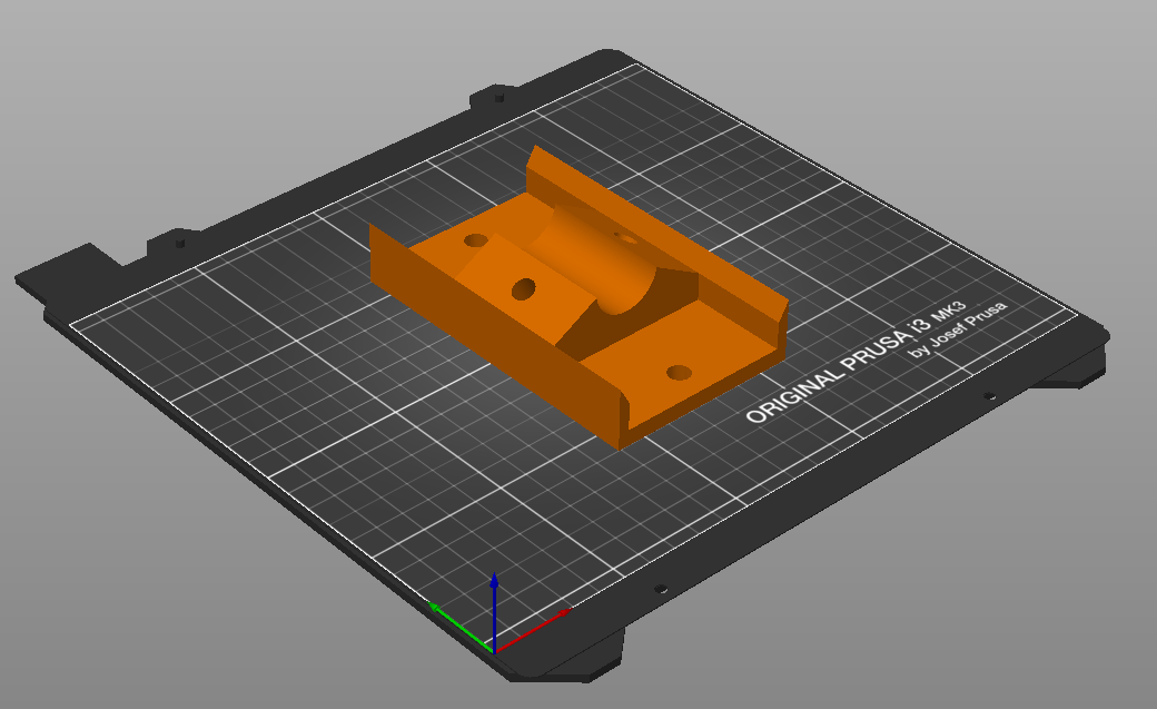
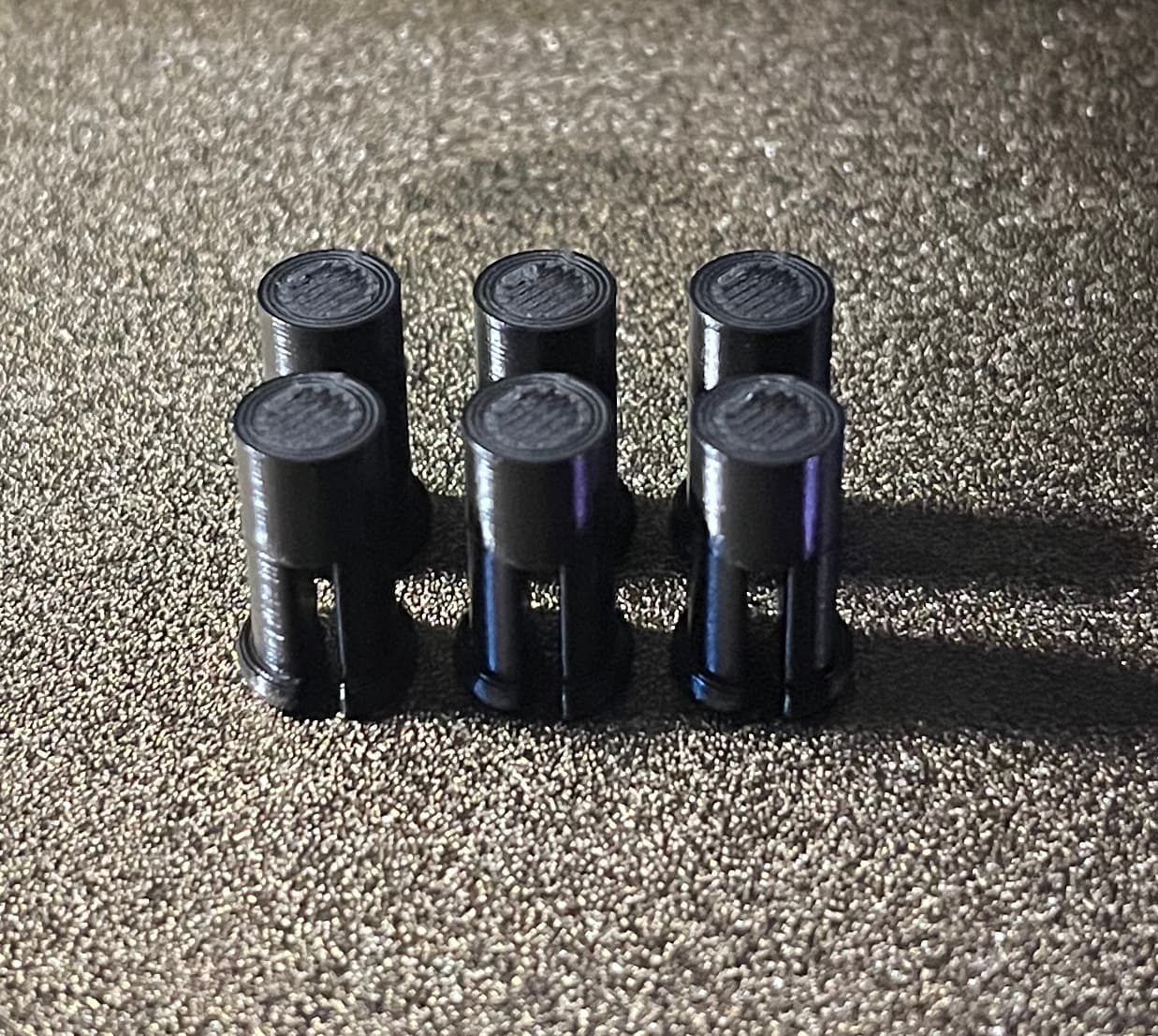
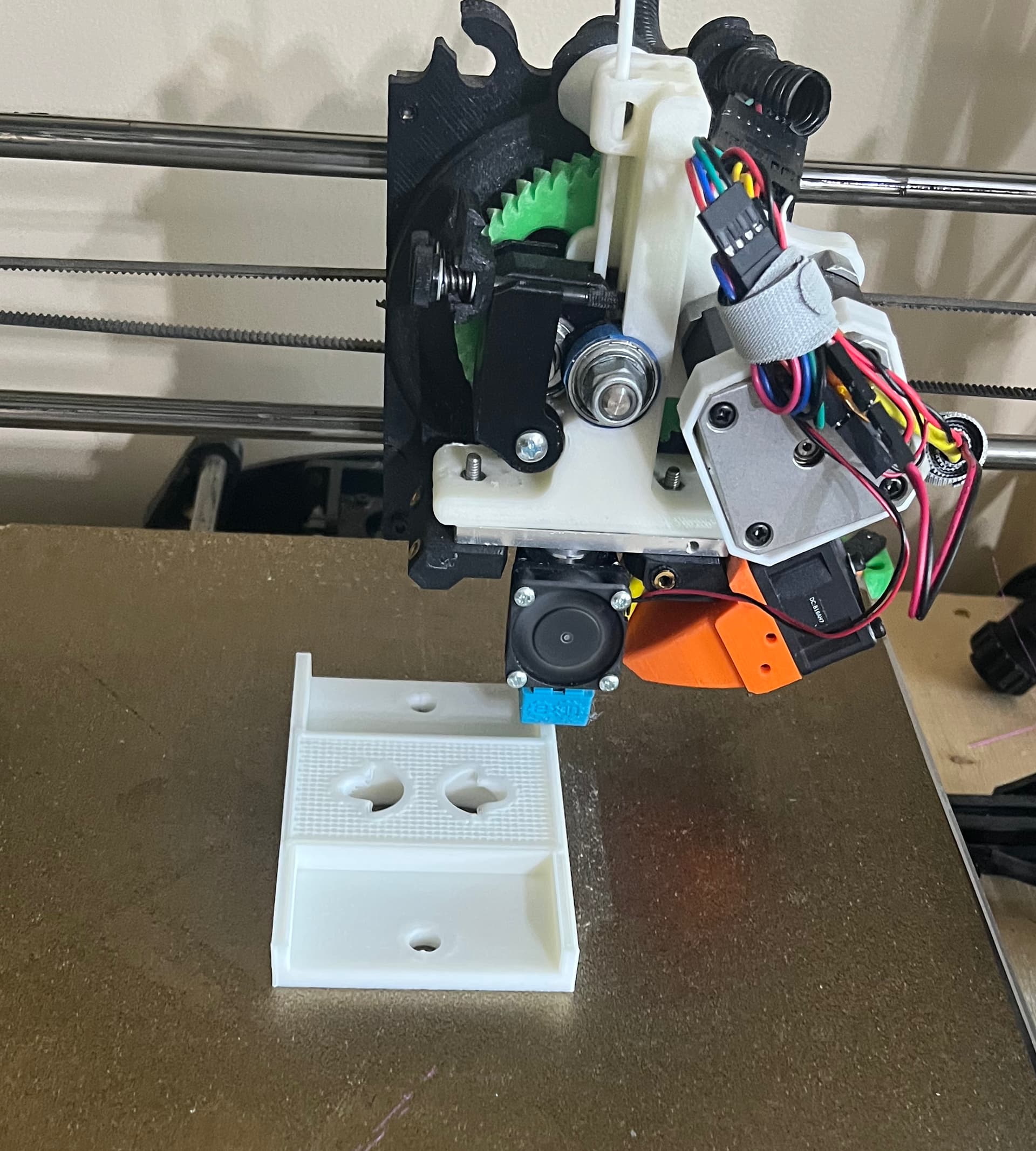
It also spit out these pressure clips

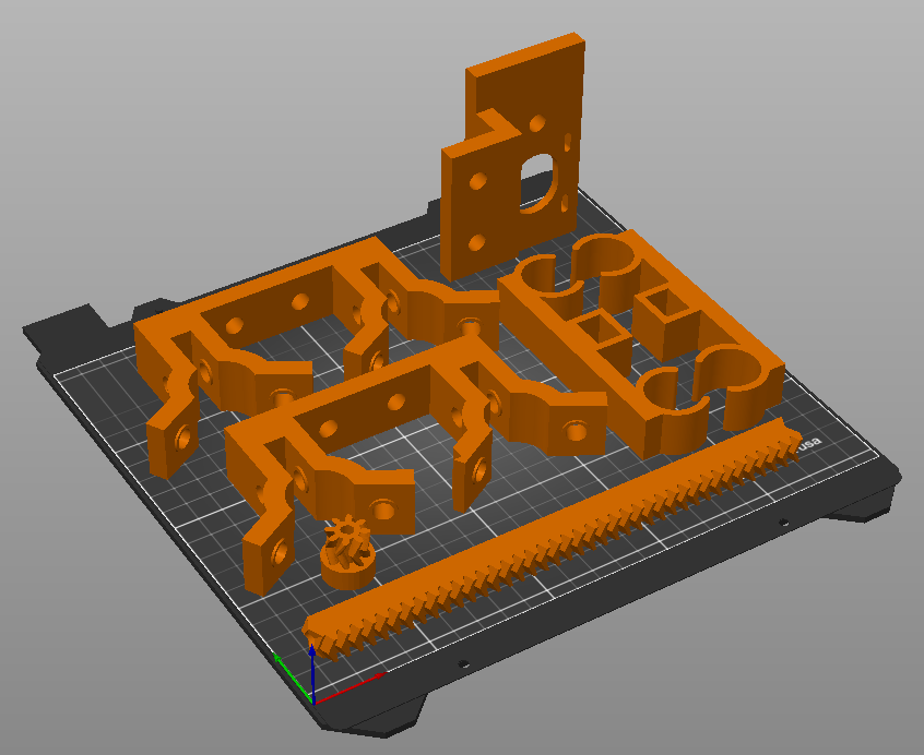
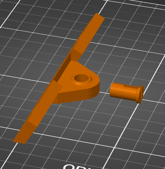
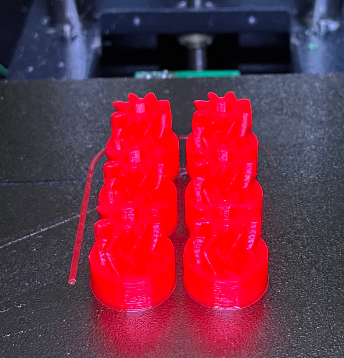
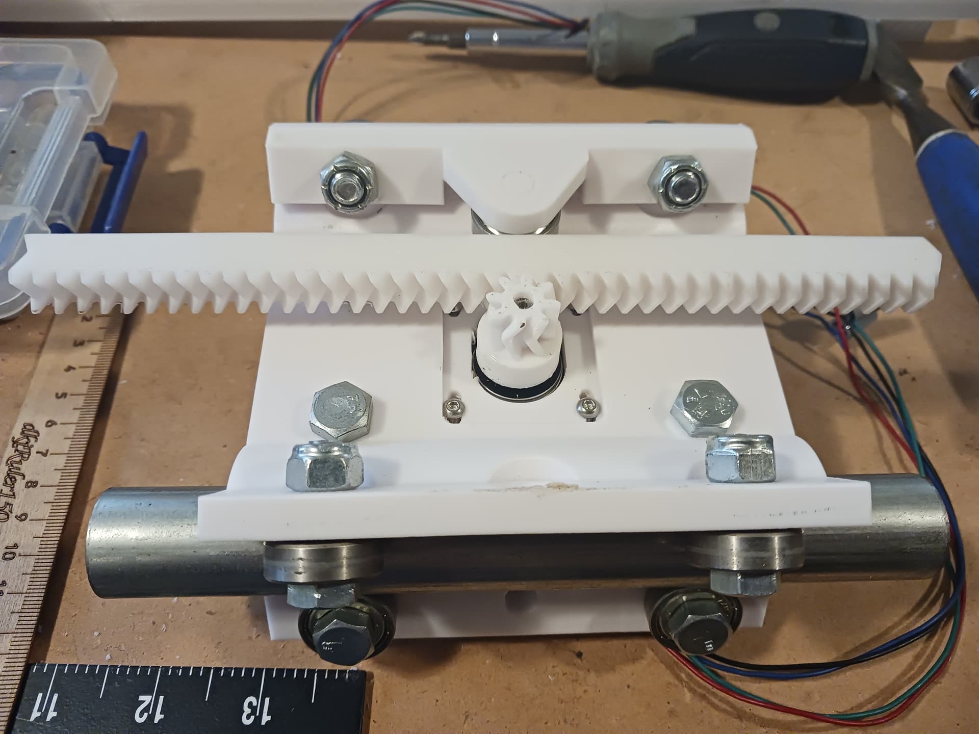
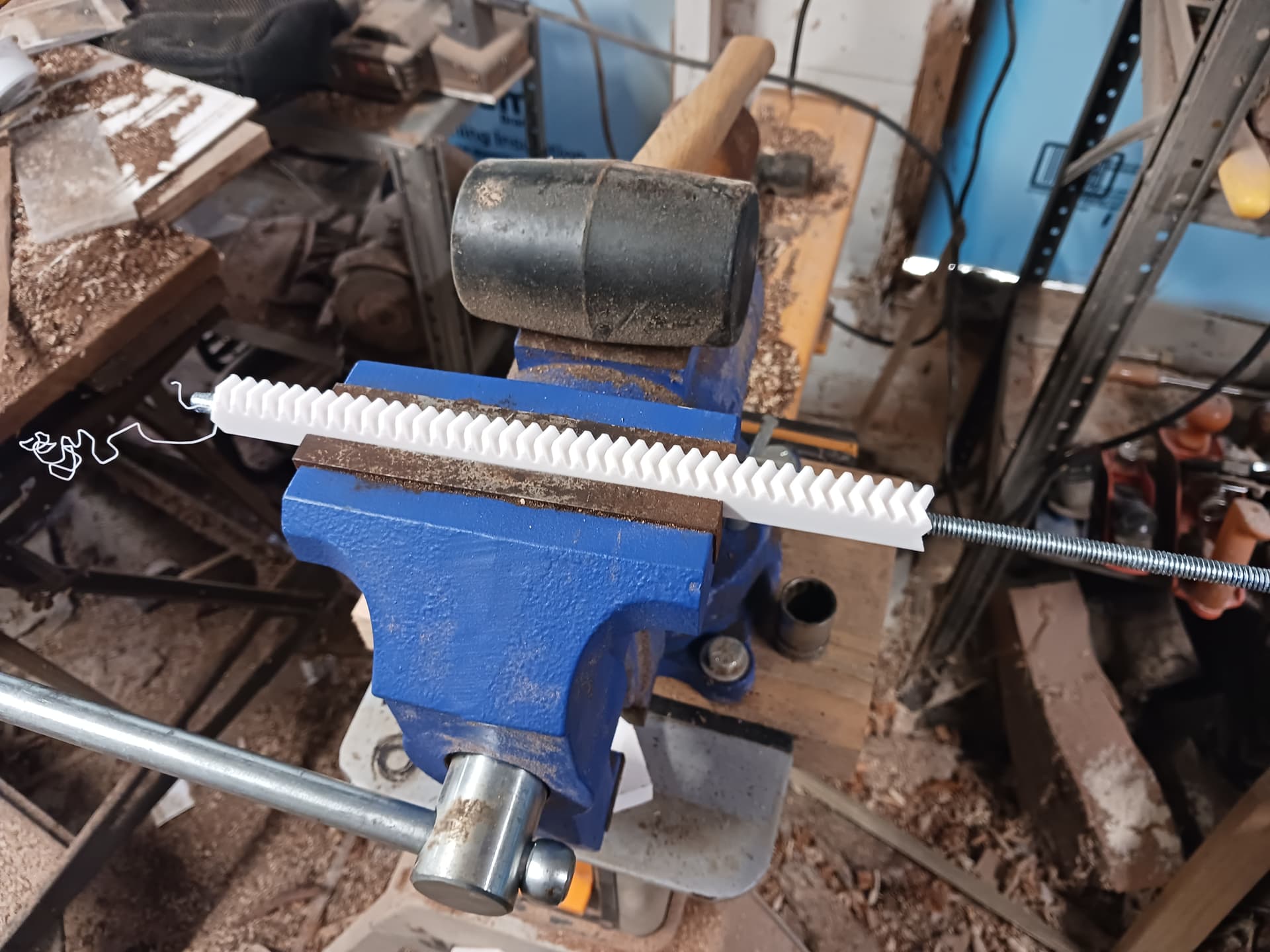
Two of the FFCPs were busy spitting out 40 tooth rack segments. 12 in total, 11 in red and 1 in fuscia. One of them also spit out a plate of motor gears. I realized in looking at the TAZ that those looked suspiciously similar. In fact, I reached into the TAZ parts bin and dug out a partial extruder kit and low and behold: it fits the rack like a glove.

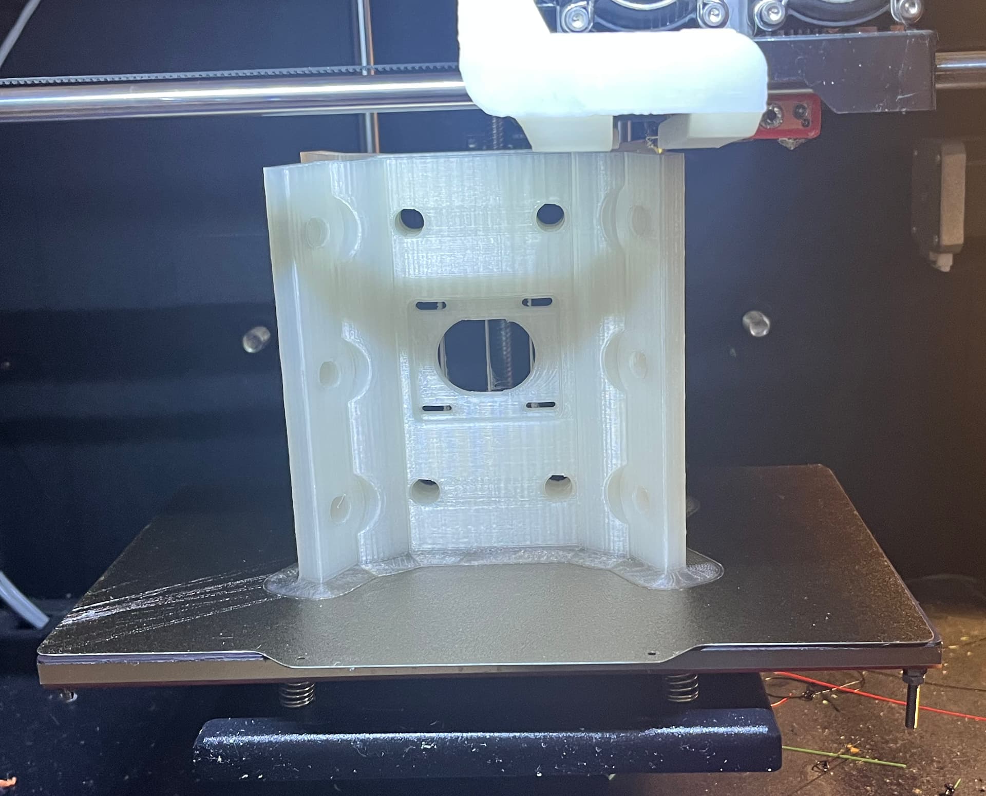
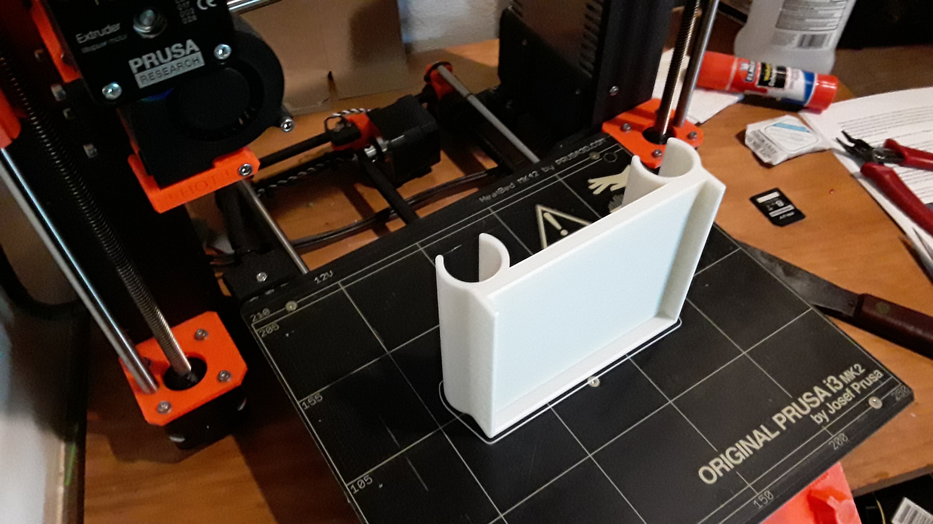
Sorry it’s washed out, dark room bright printer.

There’s always fun when using old leftover materials and my older printers.

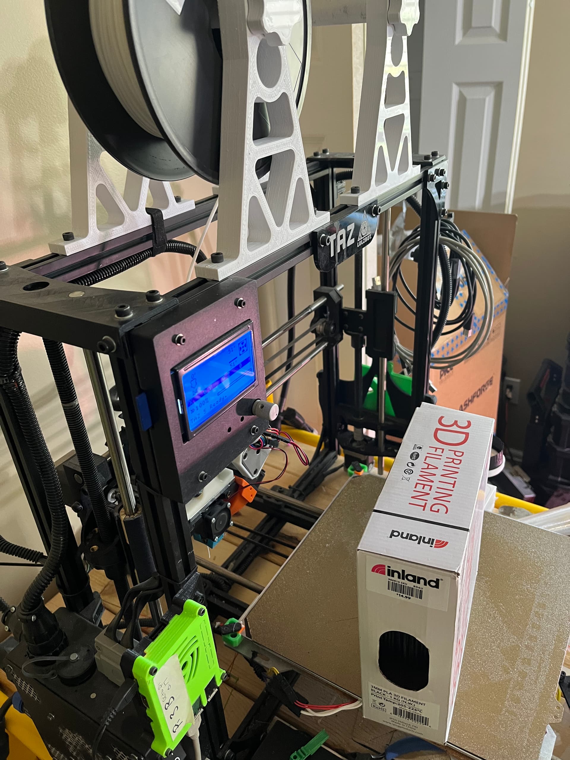
TAZ was chugging along, about 4x as productive as the FFCPs at big parts. But, Octoprint froze mid-job. No idea why. It just froze there. and octoprint log had zero indication why Octoprint blew up.

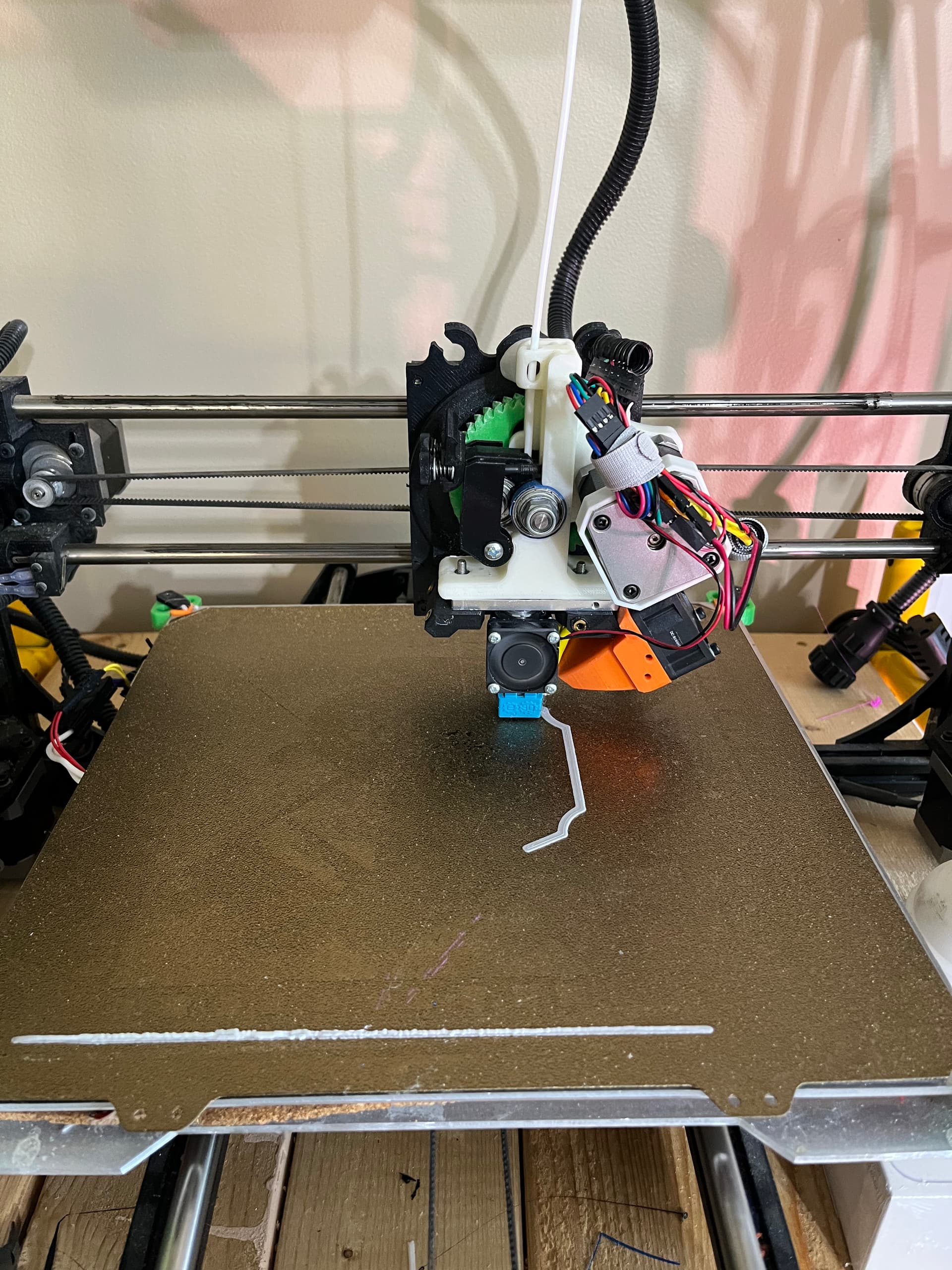
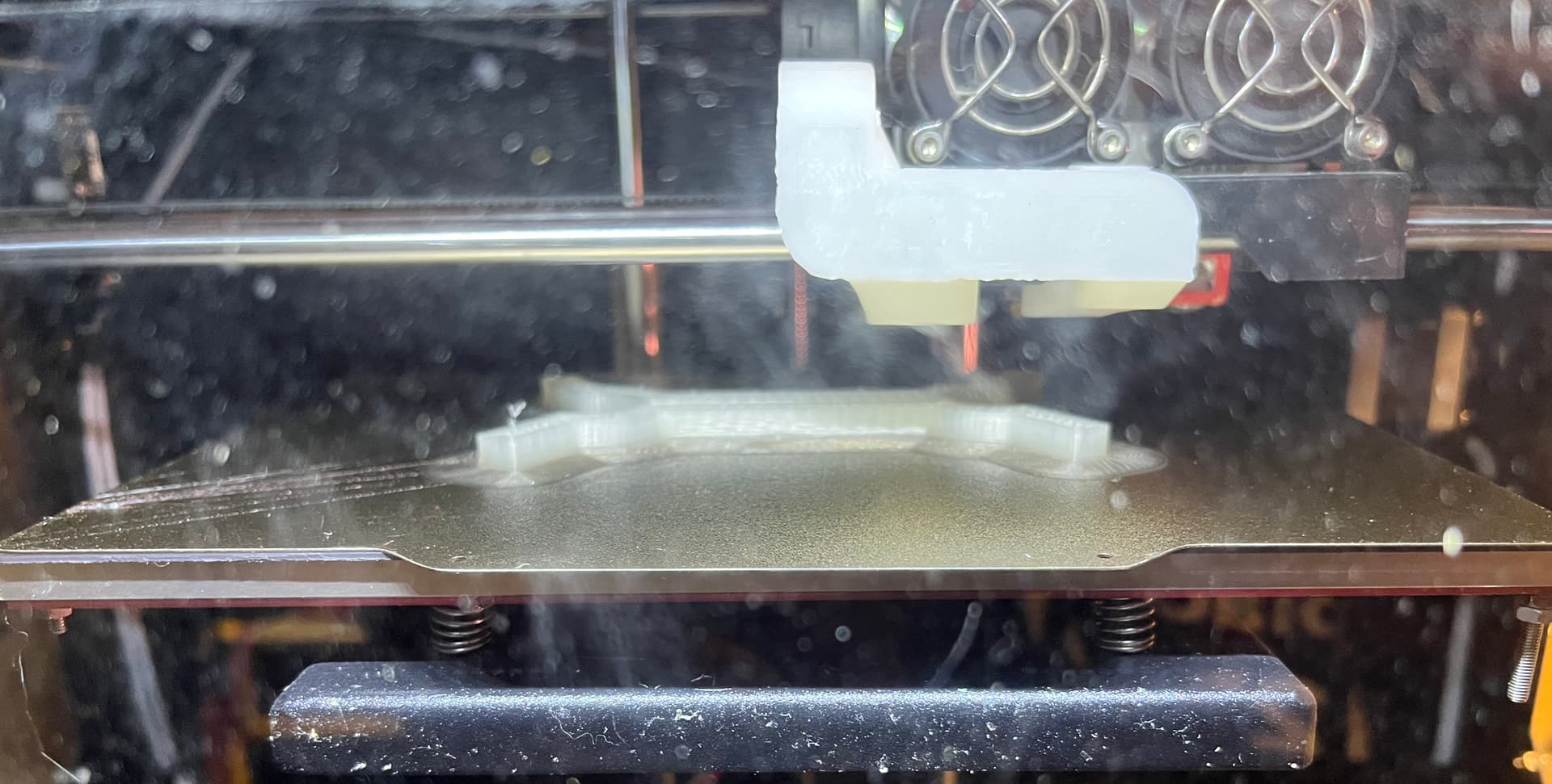
Over on the QiDi Tech one (FFCP clone), I cleared the clogged extruder. First time I’ve ever had the Flexion clocg on this machine. I found some old natural PLA in the garage and kicked off a print. The I realized it was air printing. Whiskey Tango Foxtrot? (Ancient, brittle PLA broke)

Meanwhile, found another partial spool of white 2.85mm PLA in a box of ABS spools. I really need to find some local maker with a TAZ to sell or give those ABS rolls to. I just don’t use it these days.

Kicked off another print, this one has for sure enough to print a set if Octoprint doesn’t freeze. I think I may have killed it by having two different machines with browsers open to it. Bad, Jimmy, bad.

Shame I don’t have a filament runout sensor; I may attempt a manual filament change to try and get every last bit out of those remnant spools.

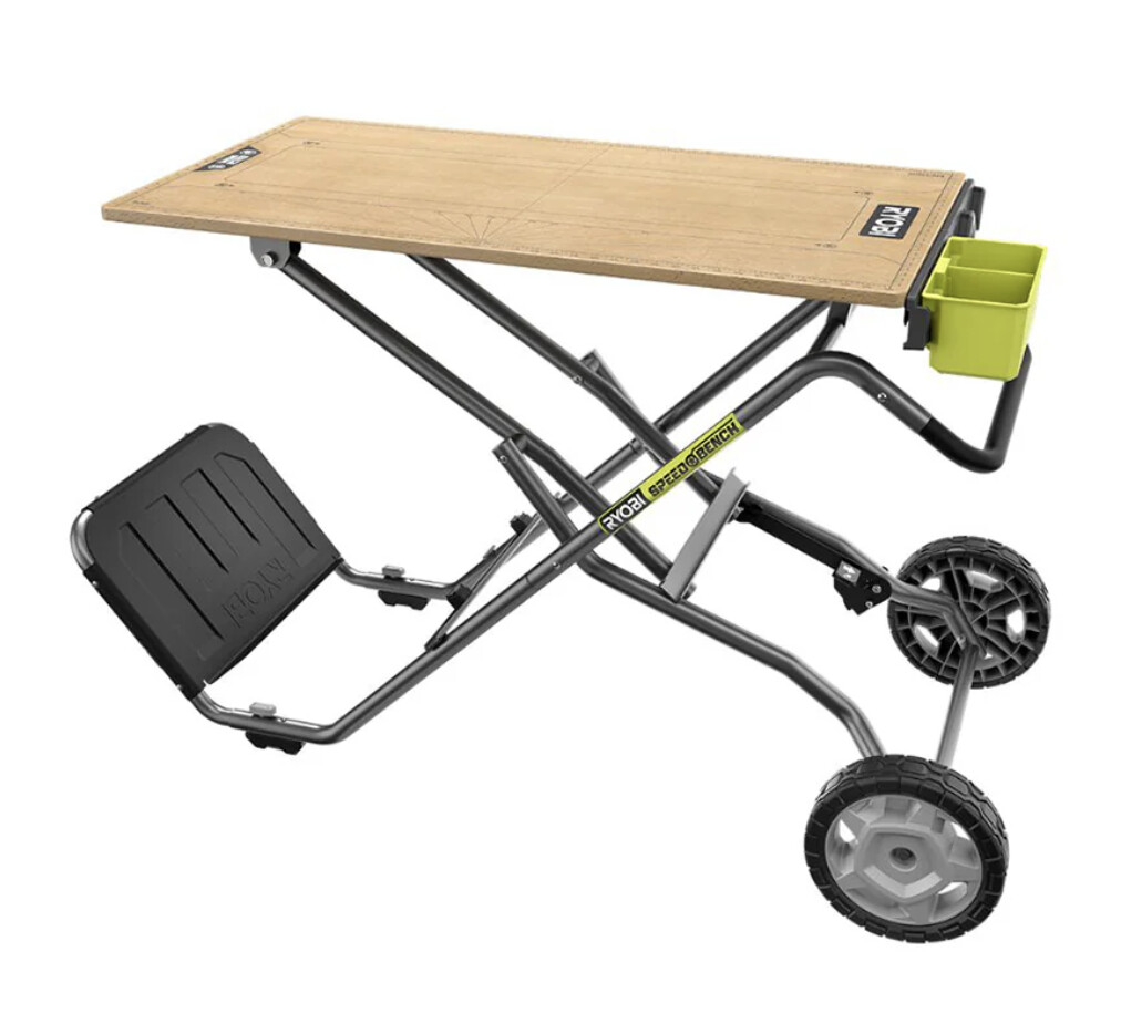
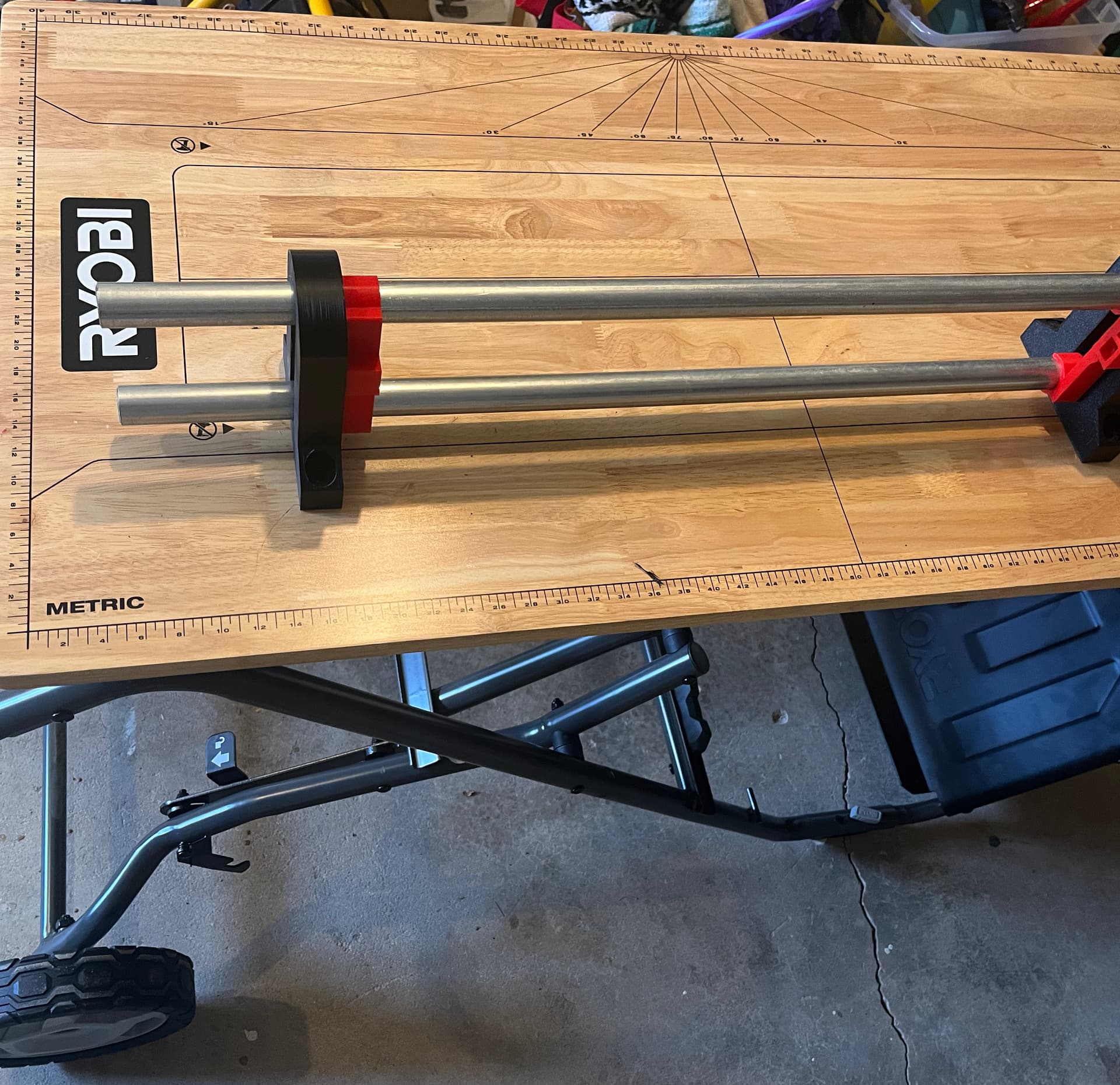
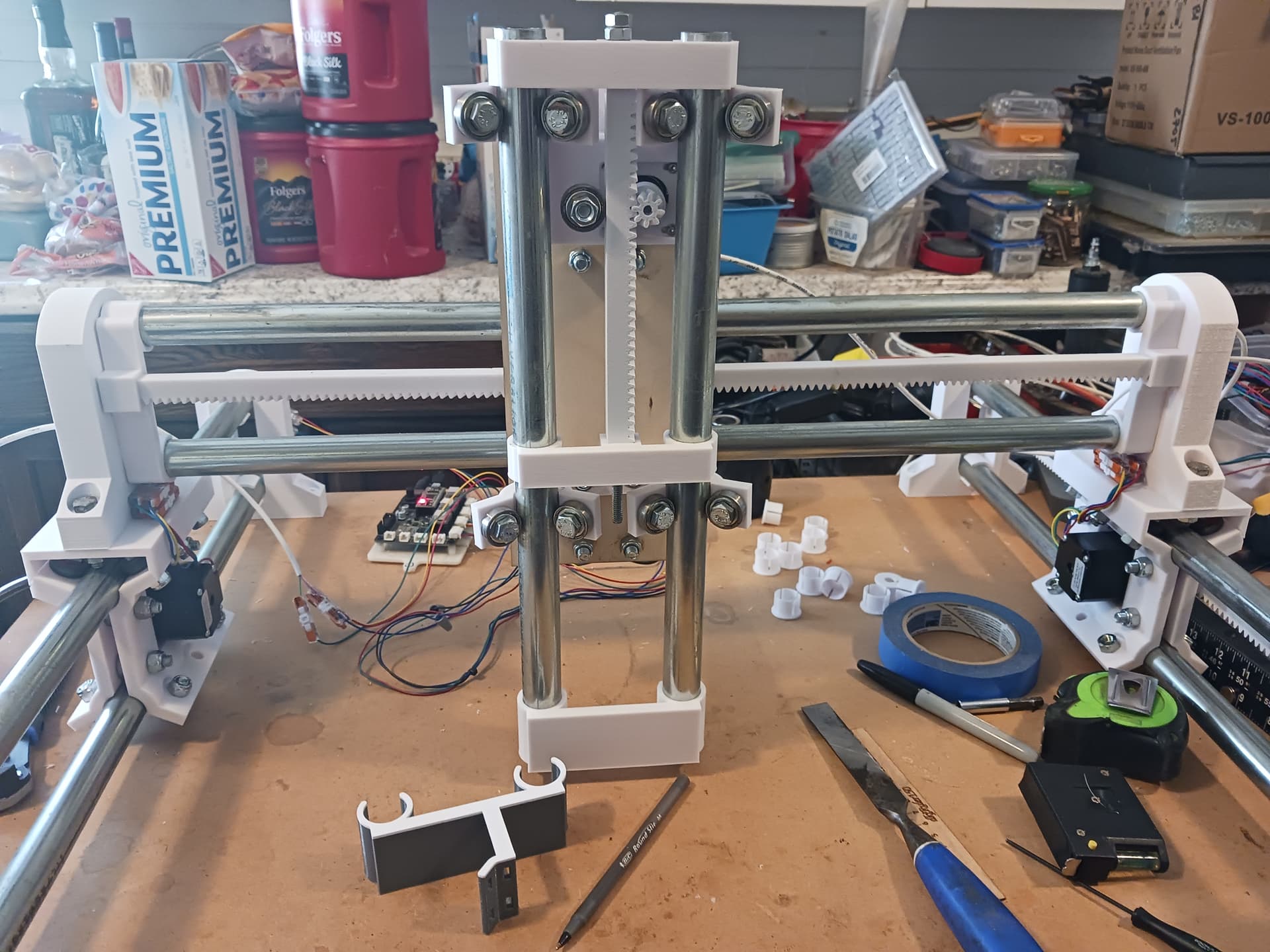
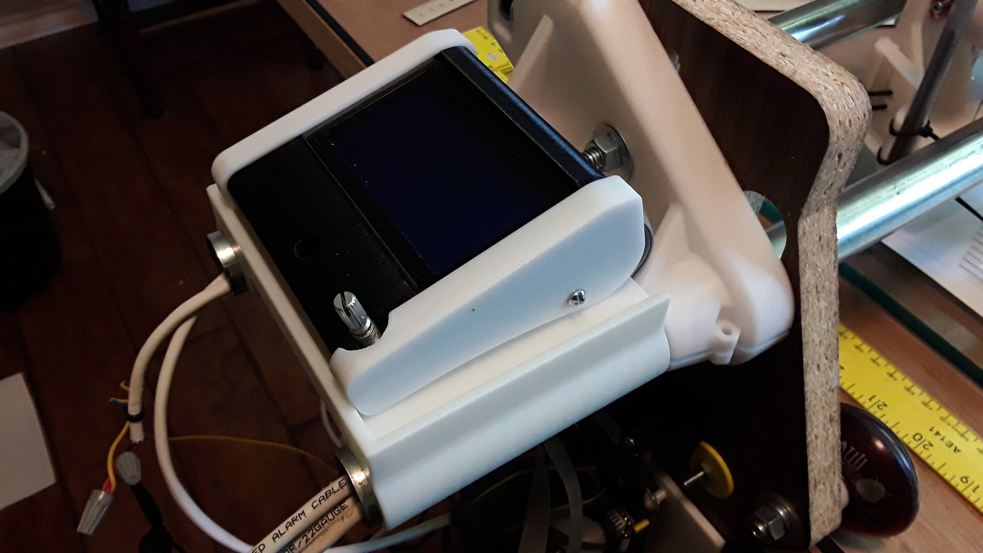
Tomorrow I may do some mocking up the parts on the portable bench they might end up on.

I’m also thinking I’m going to wire up my spare jackpot and maybe even Klipper with an old Pi 4 and an SKR Pro 1.2.

Also realized that you use the machine without endstops so I started noodling over what/how to add some.

Was near 90F today outside, will snow tomorrow PM. Springtime in Colorado. We’ll see how much progress I make.

One other closing crazy idea. I am considering making some little supports to put under the lower EMT, down to the table, essentially making for a poor mans’ SBR.

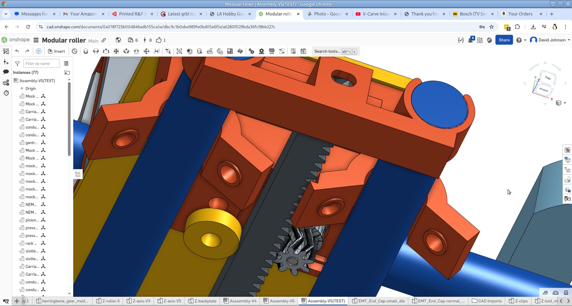
Tomorrow will be printing more parts, doing the mocking up, and studying the Z axis.

3 Likes

I absolutely love what you are doing, Jim. You are so blessed to have the resources and talent… I’m amazed and thrilled. Please feel free to innovate as you go… nothing I did is sacred; i.e. I just followed my nose to a very basic machine. I’ll be thrilled to see what a real professional can do with this thing. Upgrades to the controller, added support and rigidity, limit switches… I’m waiting anxiously to see what you have when you start mocking it all up!!!

What does that portable bench look like?

:smiley:

It’s one of these:

Take it to a show (or worksite, or makerspace), use it to haul the setup, then host the machine.

3 Likes

Fantastic! This is so cool! I’m so excited to see all this… it’s so far beyond my wildest dreams! I was just fiddle-farting around for a couple of weeks… thinking I’d like to do one more scratch-build…

:flushed:

1 Like

I plan on making a plasma table. I’m more worried about heat than strenth

1 Like

For benefit of any who are watching this thread, when building the “clamshell” carriages it is best/easiest to preset the rack/pinion spacing and roller bearing to rail tension. I do this with a spare length of rack and short piece of conduit during assembly.

The topmost slotted motor screws and central bolts are covered up once the carriage is placed on the rails and mated with the rack. The four central bolts are adjusted to remove any play from the roller bearings and conduit interface and the motor mounting screws adjusted in their slots to give firm but not-too-much pressure pinion on rack.

The pinions are also designed to press fit on the motor shafts. Align the flats and gently press into position with a vise or clamp… the central “V” of the pinion should be aligned with the central “V” of the rack. One advantage of the herringbone rack and pinion is that they tend to run centered on one another without drifting out of alignment.

2 Likes

Very timely post!

The TAZ early this morning knocked these out:

Started up a new print, nearly done as I type this:

Meanwhile, the QiDi Tech one was still going along with this set:

On the real FFCP :

Also the other clone had a twin to this.

Ran out to the garage to find some leftover EMT (This build is using EMT from an LR3 build that was abandoned for my LR4 beta builds.). Keeping with the found materials theme.

Mocked up to see what it looks like. Note: This is surprisingly stout!

Seeing this, it occured to me that I could deliberately cut or leave the tubes long, and then use the tubes as mounting points for things. E.g. the controller box is likely to fly up on the X axis.

Now going to rummage about looking for the 1/4-20 rod that I know I have around. Some of it goes way back to early reprap builds.

1 Like

What length of fastener did you use? I’m starting to dig now through my LR build kits to find hardware for the carriages. Also digging for bearings to use.

The “clamshell” hardware I used is 5/16" hex… 1" long for the plain outboard roller bearings, 1-1/4" for the roller+pressure-bearing mount, and 1-1/2" for the four through-bolts holding the "clamshells’ together. I also used nylon lock-nuts. It’s best that hardware lengths be as short as proper to avoid interfering with something else down the line… also the hex head is thinner/shorter than the end with nylon lock nuts and may help determine which direction to place the bolt; i.e. “clamshell” through bolts want heads on rack side of carriage.

The 1/4" threaded rod is not only for stringing rack sections together… but be sure and tap/run a 12" or so rod through each rack section from both directions, to remove strings and debris in the bore and insure it doesn’t find its way into the rack joints.

2 Likes

Here are a couple of quick and dirty tool mounts… nothing heavy as they just clip to the bottom of the Z-rails. One is blank, the other for pen. I haven’t actually used the pen holder yet… seems pretty stiff but stylish. :roll_eyes:

STLs and .3mf file…

Z-tool_mounts.zip (201.0 KB)

5 Likes

Cool, more stuff to throw on the print farm!

Lots of parts printed, starting to think about how to lay out the machine on the table and how big I want to make in Y.

I plan to make a small table addition that bolts in to the existing inserts (on the bottom side of the Ryobi table), Making it truly portable and (hopefully) easy to set up and tear down.

Doing some noodling on how I want to attach a controller box using a modular system so I can swap between Jackpot and maybe Klipper control systems for showing the different options.

Still thinking about endstops, and fairly certain now that the carriage supports should have a symmetric set of cutouts that match the clips, so that threaded rod can pass clear through. It would make assembling the carriage easier and even allow for customzing the size of the machine as-you-need, any time you want.

Debating using the leftover LulzBot steppers vs a larger set with more torque.

Here’s the state of things as of this morning. Still need to print the pen mount and get to some more axis assembly.

4 Likes

That’s looking good, Jim. This machine is gonna be really neat once you’ve refined it and made it into a real product. I love the portability if you can make it robust enough.

I once used the over-long conduit on a machine to support a shelf… essentially a larger version of the blank tool mount. You could easily print something similar that firmly clips on to the over-hang… maybe a complete enclosure for your controller boards?

I agree completely with using the threaded rod to tie the linear stage all together. But with only one printer I’ve fought the idea of taking the time to print another full set of slotted ends… and I didn’t want to just drill through the existing plastic ones. But it occurred to me last night that I could easily laser-cut thin-plywood (~5mm) versions of the slotted ends – with the holes – and then sandwich the ply and plastic together and match-drill through the plastic. I’ve got room to leave them sandwiched together on my worktable… you may want to reprint the slotted ends with holes since you’re gonna be pretty limited in the narrow-axis. They’d probably add some stiffness to the assembly as well?

I know you are not showing a complete set of printed parts in your photo. One thing to note is that the clips for the Z-axis assembly are NOT the same as for the other axis, since the Z isn’t identical to the others. The pressure-bearing/rack/pinion relative placement is slightly different. Also note the notched roller and inset plain nut … required for rack clearance. The notched roller assy is the top-most one on Z-axis.

Later.

3 Likes