Printed R&P X/Y/Z Platform from MPCNC junkbox

I was noticing this over the weekend. I got a bit distracted- Saturday was just below 90F (set a record high), Have tulips blooming:

Did some protective work with the gardens, since we were forecast for snow. Looks like I missed the snow line by about 200 feet in elevation, here’s some shots from my commute to the office this morning:

I REALLY like that, and it amazes me that what I pictured in my head after seeing the machine laid out is EXACTLY what you’ve already made.

I’m just a machine builder that plays with this stuff because it’s so much fun. I’m really loving this experiment with a step back closer to “mostly printed”. such fun.

2 Likes

We were close to 90 degrees Saturday and Sunday as well… but that’s pretty normal for East Texas. My grandmother used to say that Easter marked the “last freeze” date and after that she’d go ahead and plant her more tender garden plants.

I love seeing the snow-covered mountains in the distance. I’m no judge of just how far you traveled between those two photos but looks to me to be a fair distance… 20-30 miles? How long is your commute? I drove into Dallas, 5 days/week, for 23 years before retiring… ~150 miles, round-trip.

I’m glad you like the shelf. Once I started “clipping” things onto conduit, I found all kinds of uses for it.

I also enjoyed immensely building machines in the past… but have slowed down now that I’ve gotten so shaky and decided I didn’t want to add to the undocumented clutter my kids are gonna have to deal with after I’m gone. So instead I started buying more popular, nice machines (laser engravers and such) to leave to the kids… store-bought units complete with documentation and YT reviews and online support.

Now that the kids have nice useful machines to inherit, I actually just started this project thinking, “one last time”… and I’ve enjoyed myself immensely! It IS fun, isn’t it? And I love the collaboration with you and other forum denizens… it brings back fond memories.

– David

3 Likes

Trick of perspective. That distance between the photo with the two big dish antennas and the property with solar on the barn- it’s about a mile traveled. It’s basically the other side of the hill from where the antennas are, and about 200 feet up in elevation.

Edit: Those are foothills. The mountains are behind them and covered by clouds.

My commute is about 14 miles.

I’m having a blast.

3 Likes

Even match-drilling gives ratty-looking holes in the existing plastic supports. I suppose I really don’t need to drill but one hole in each support since they are symmetric and can be flipped around if you need the hole on the other side. And simple washers dress up what you can see…

But… I kinda like the look of the white plastic and laser-cut ply sandwich! And I have the room to add their thickness to the assembly so I think I’ll just laser-cut enough ply to sandwich them all…

Decisions, decisions…

4 Likes

It’s a dectuple thick Oreo !
I like the look of the laser cut sandwich.

1 Like

Now make it completely hollow and fill with cement :grin:

2 Likes

Lol! I could probably make it hollow but I don’t have a lot of cement in my MPCNC junkbox… :wink:

Do you have a DXF of your end plates for the sandwiches? I tried rooting around in Onshape but am showing my lack of knowing how to drive it.

Sure! Got one side done today… gonna need to buy another 3’ piece of threaded rod to do the X-axis.

slotted_support-added_holes.dxf (15.0 KB)

Made myself two hack parts, posting here to keep the thread updated. One to match drill holes and maybe print endcaps, one modded part if / when I print more carriage ends.

jv_carriage_cap_v5a.3mf.zip (21.7 KB)
jv_carriage_v5a.3mf.zip (48.9 KB)

Edit- was going to fire up the JL1 to cut some end caps, but the only stock I have on hand is too thick to cut with the wimpy laser on the JL1. I could go down one of two rabit holes (upgrade the JL1 to a larger laser module, or it has a big brother sitting in a box waiting for me to set up). Instead of the rabit hole, I’m staying focused this week on working the MPR&P build as I get spare time.

I was planning on using the tubes to run wires in as well!

1 Like

Probably my worst assembly skill is wire management. I’m really interested to see what you come up with… so I can duplicate it.

1 Like

I’m still having fun with this project, working in the weekdays after dinner.

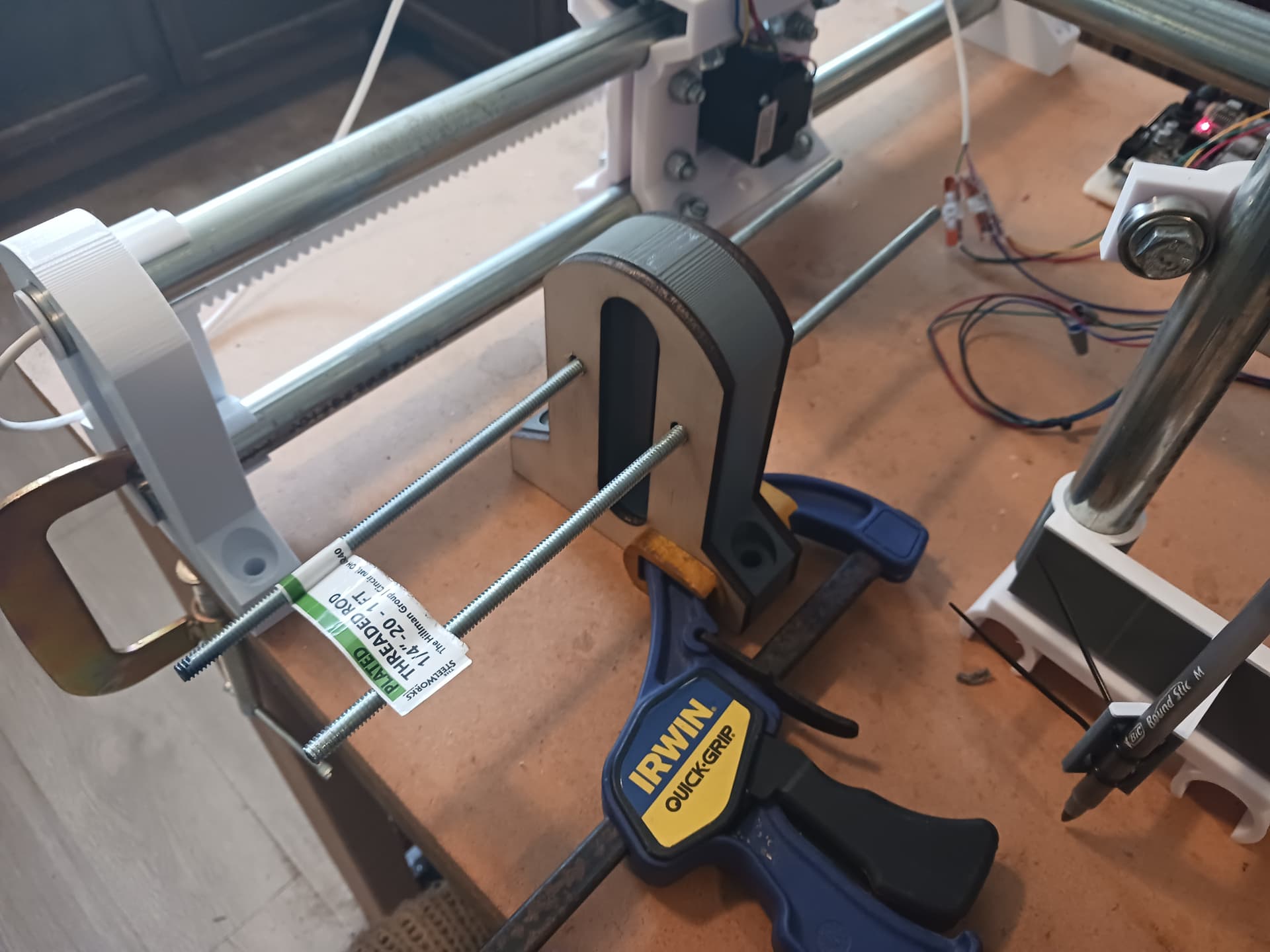
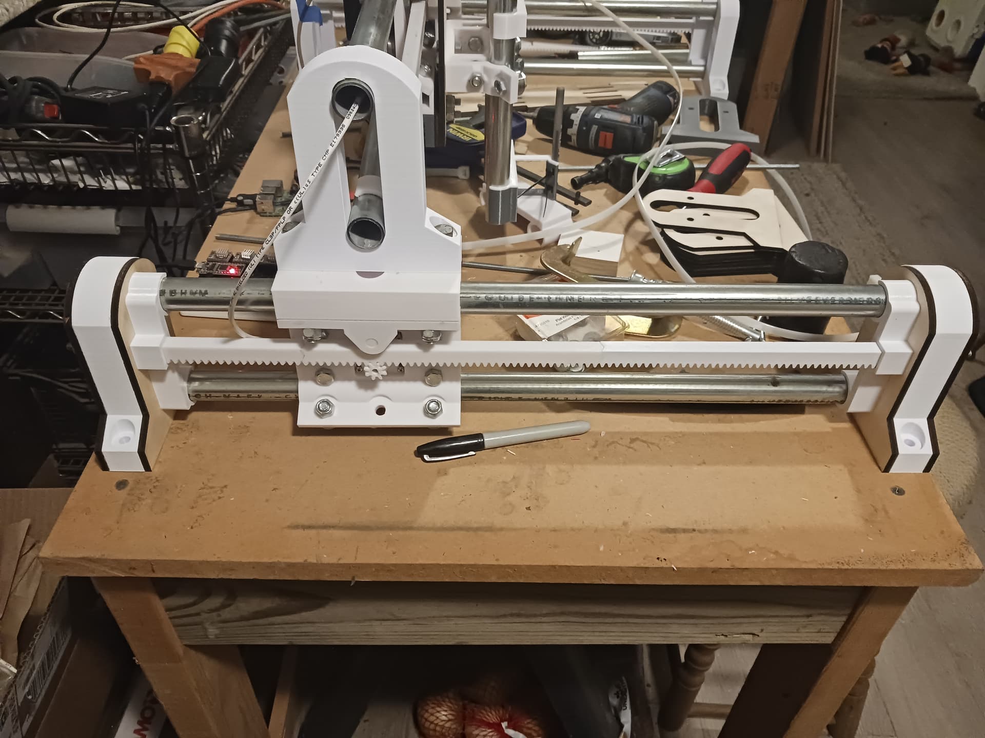
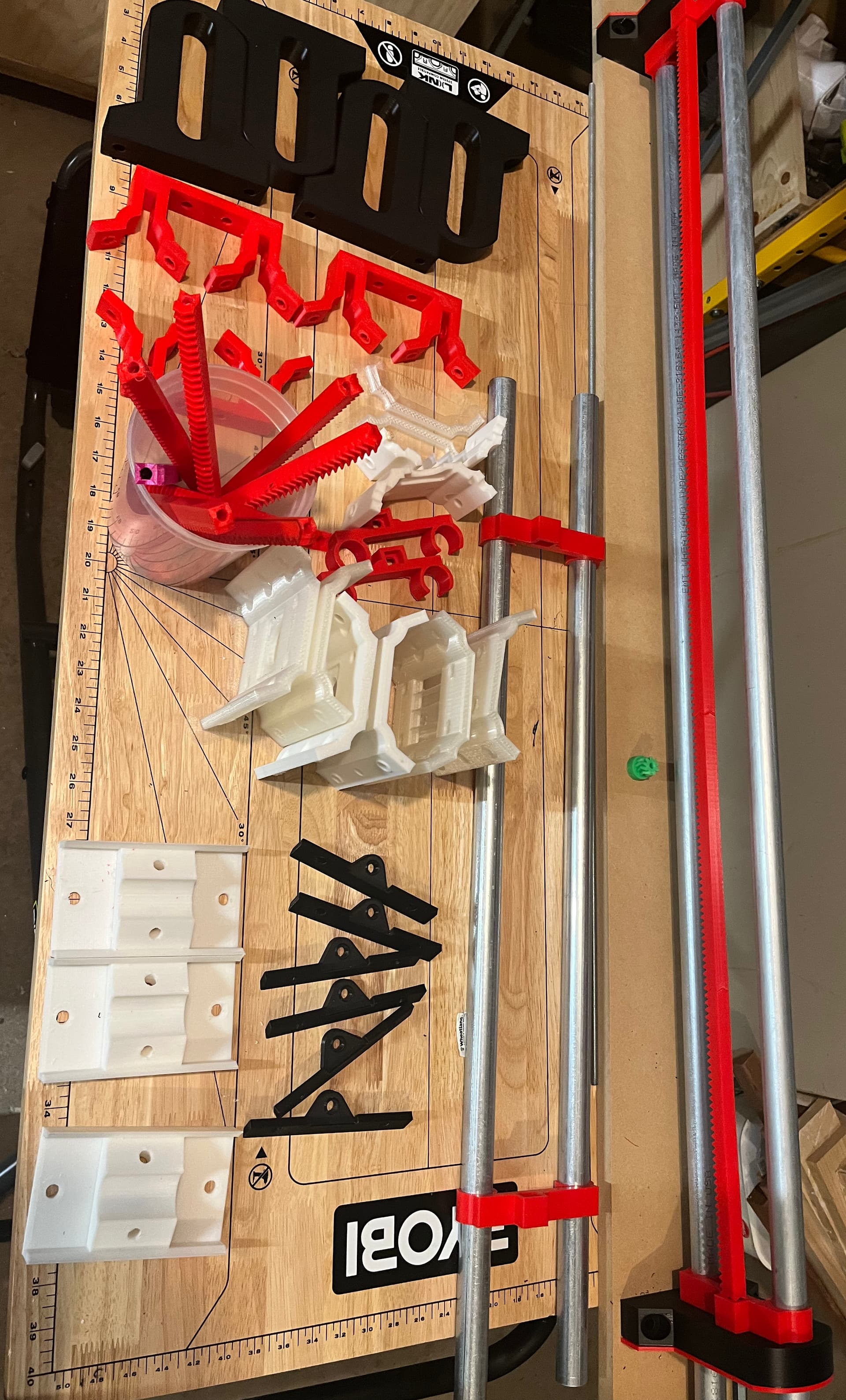
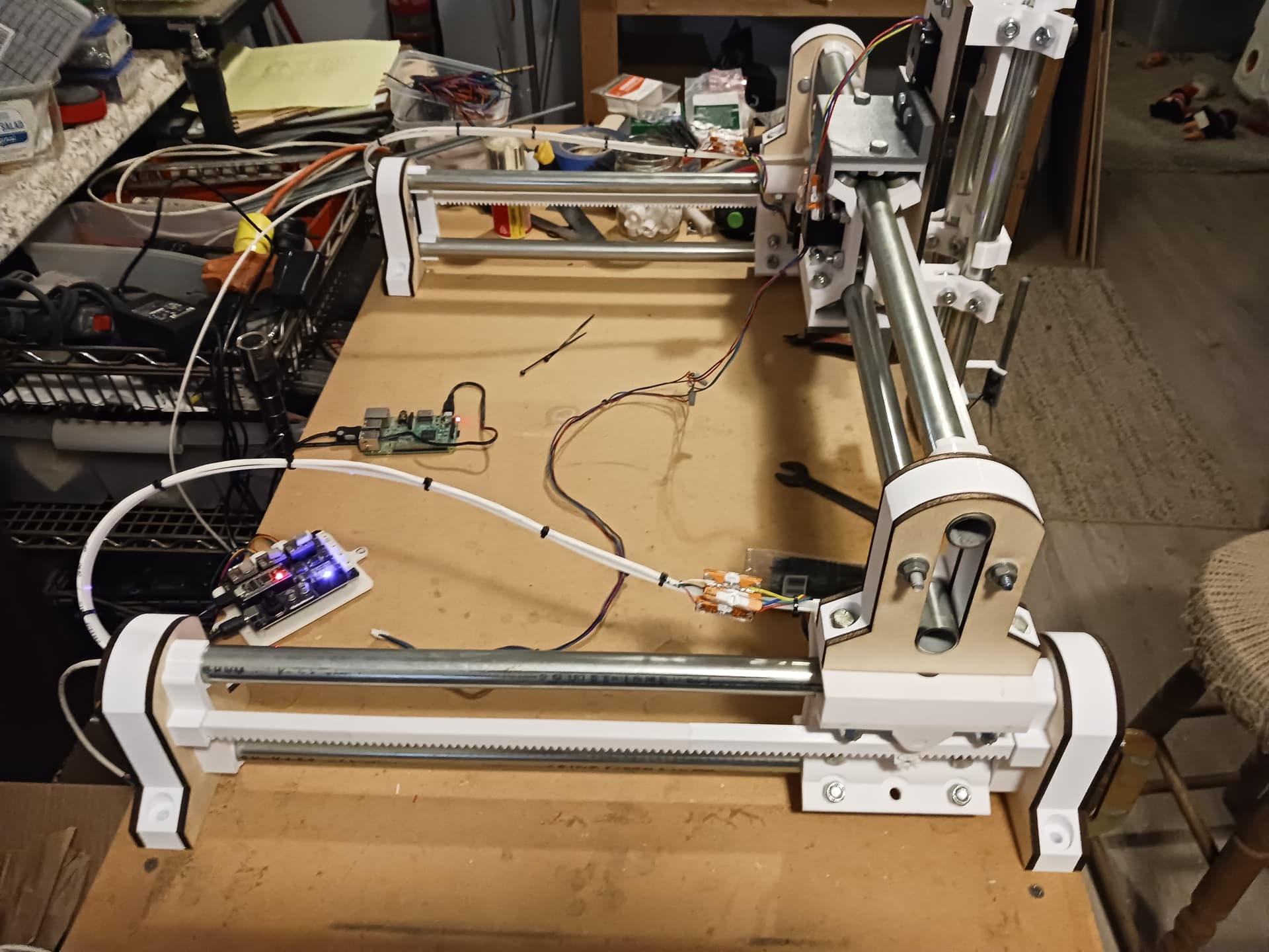
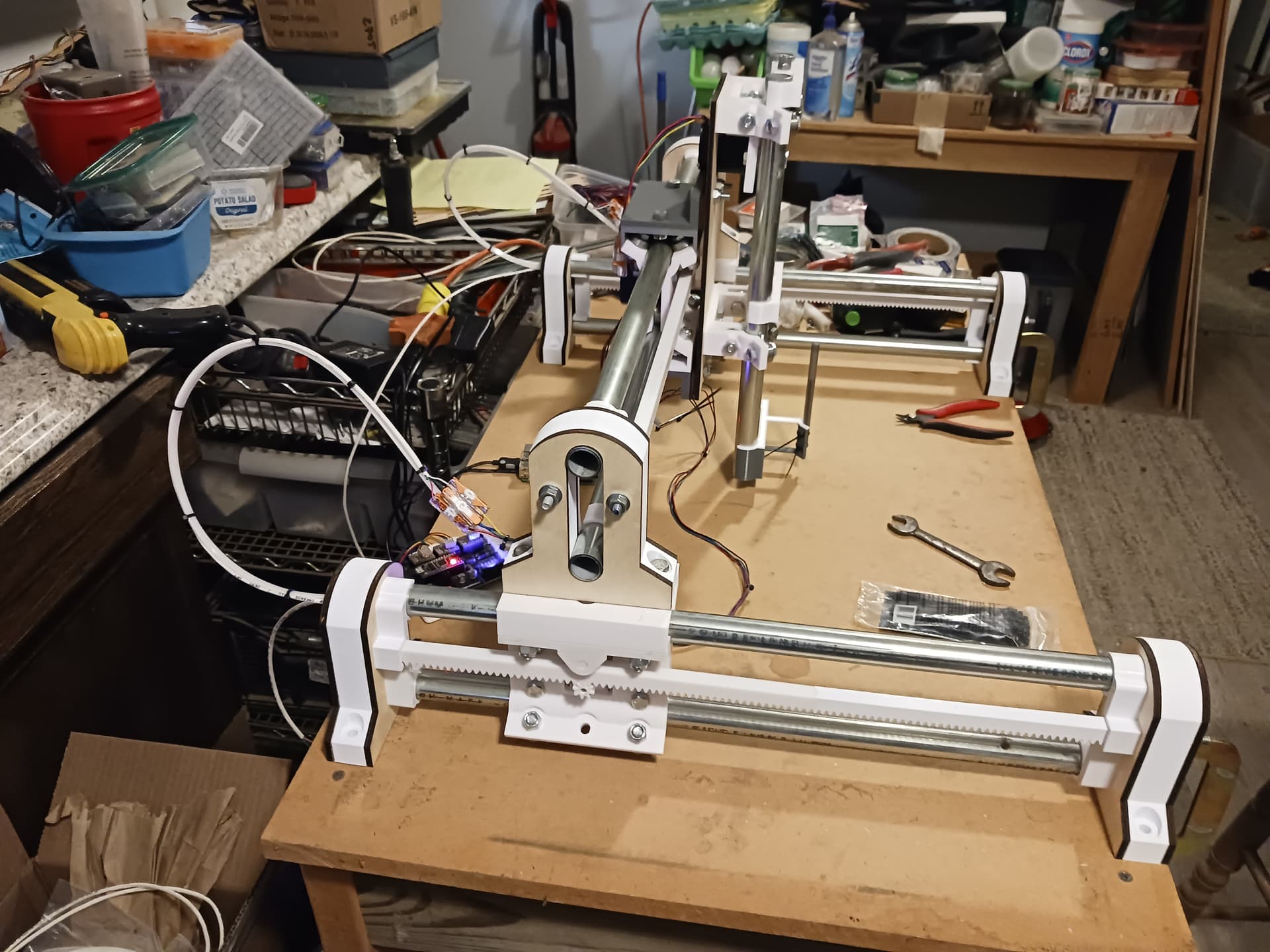
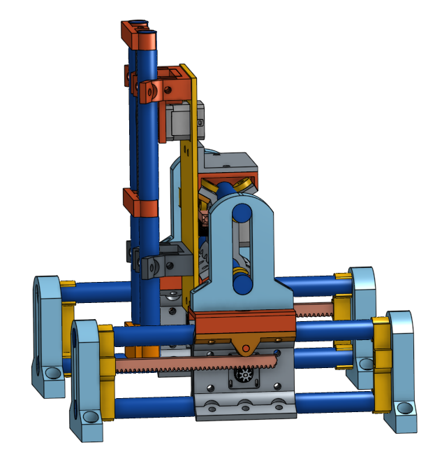
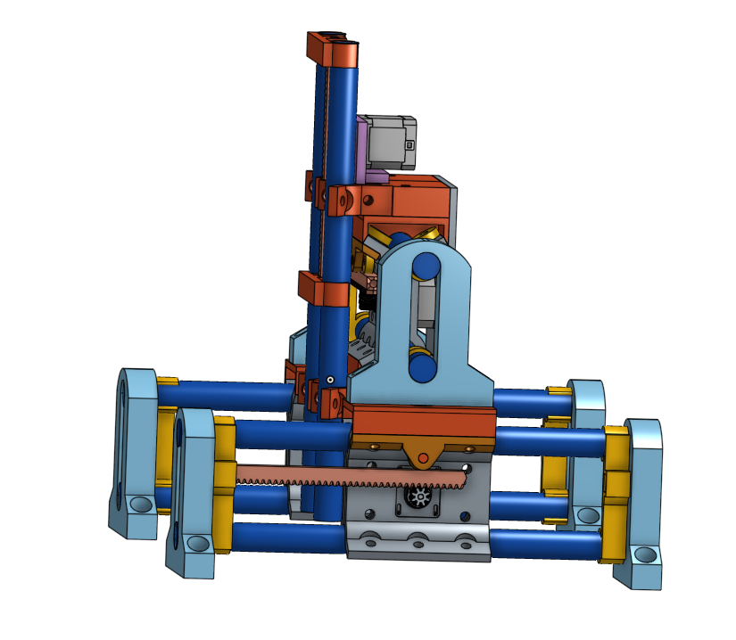
You can just make out on the right side of the picture below a mock-up I did this evening. I don’t think I’ll build Y this long (qty 5 each of the 40 tooth rack segments.).

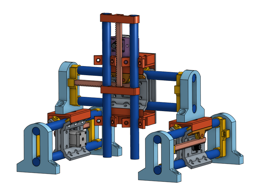
Since I’m using EMT left from the dissasembly of my LR3 project, I have lengths of tubing sufficient to test this. The mockup is sitting on one of the “Lift plates” I made for my LR4 beta build table, because it was sitting in a corner not presently in use in the LR4 table.

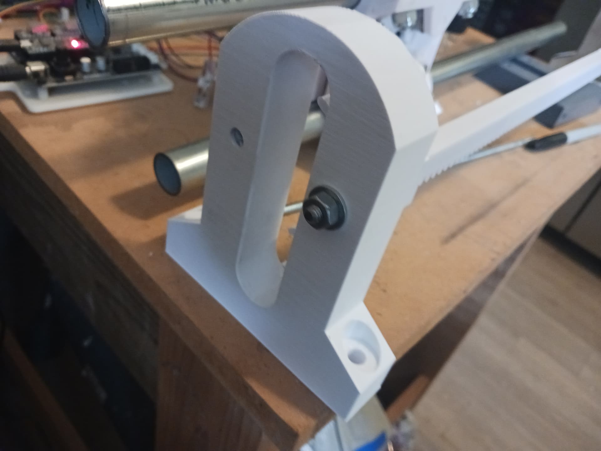
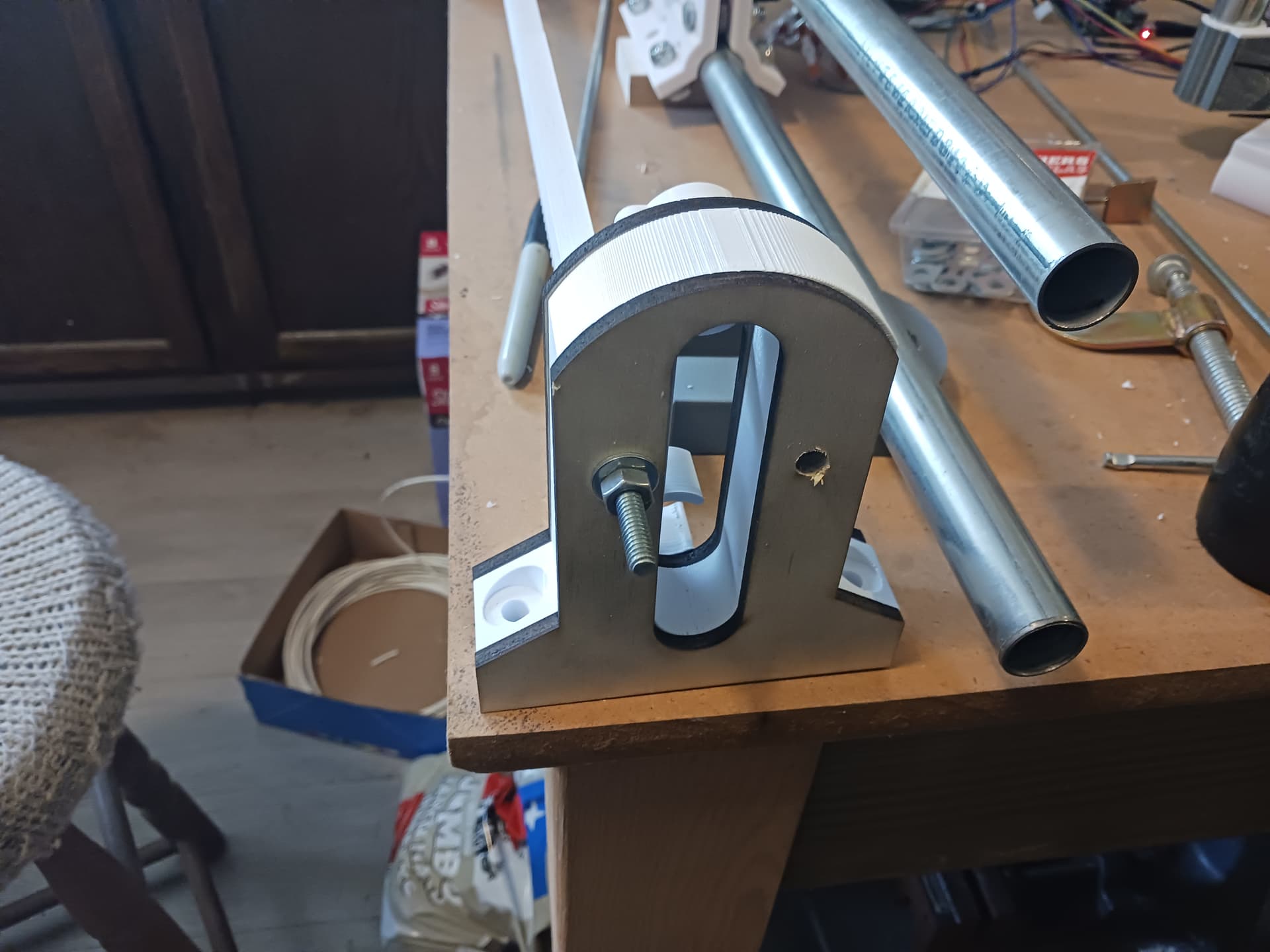
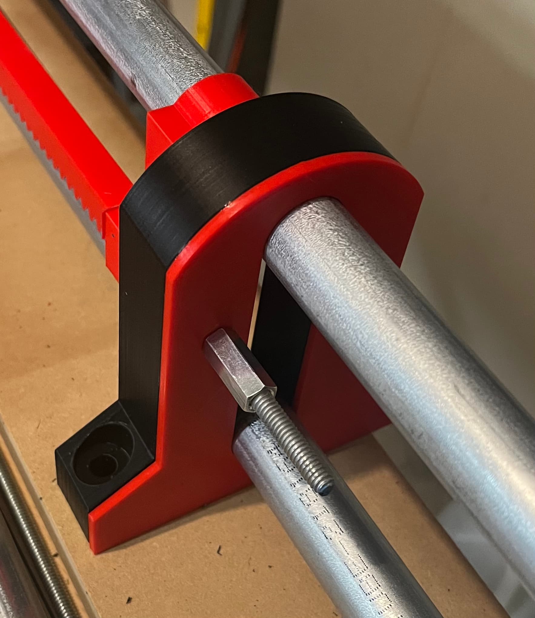
I’ve printed some caps, here I’m using a couple of red caps. I decided that with a washer under the hole i drilled in the carriage ends, it would look fine. I then looked at the red caps on the printers and said “why not see how it looks.” So there’s a v1 color theme mockup, minus the DKJ white center parts.

The 1/4-20 rod and coupler nuts were sitting in a storage closet in the garage. The rods will get cut down and I’ll find some Nyloc nuts at some point but for mockup work it’s fine.

I think it looks great in V1 colors!

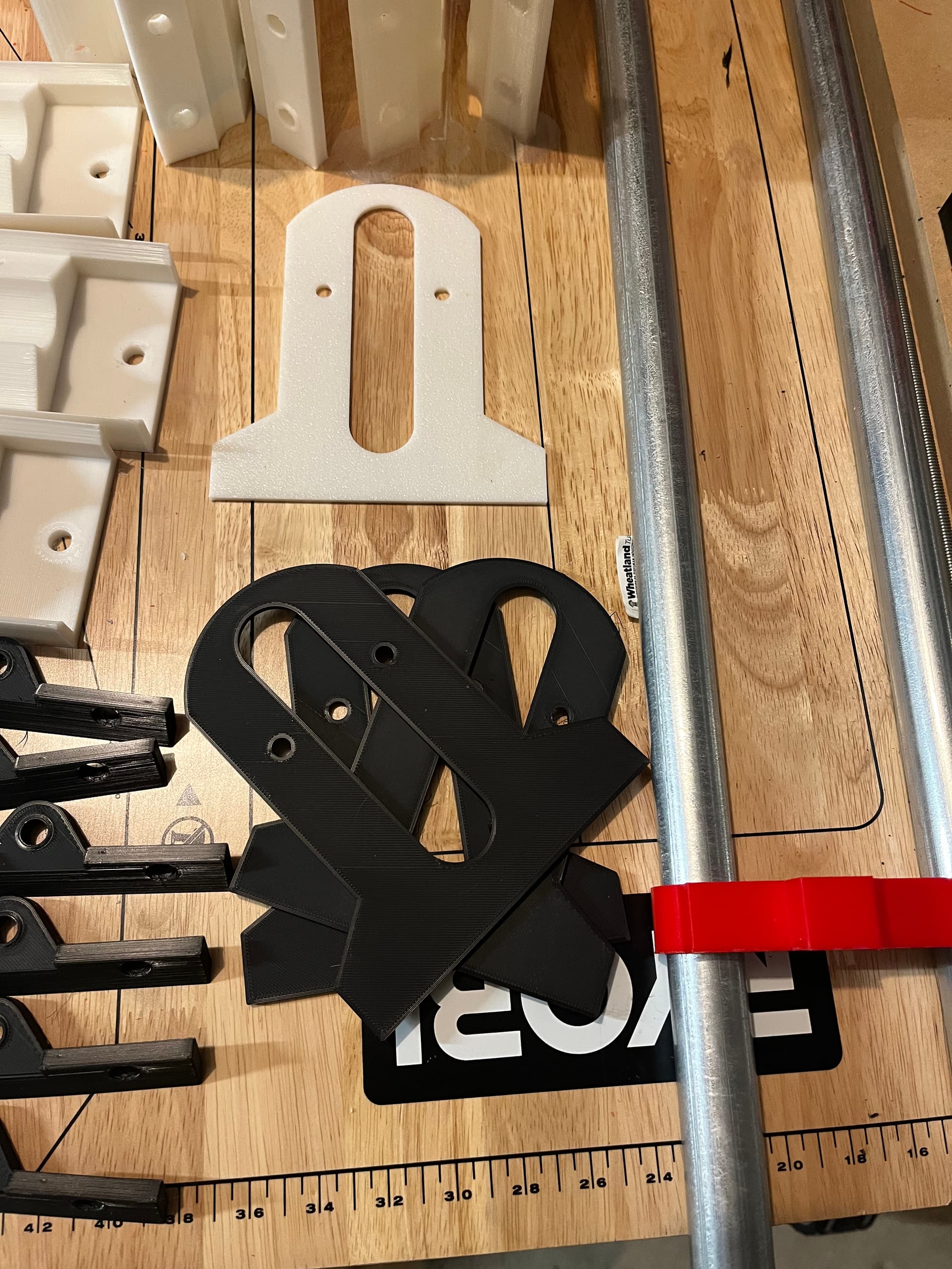
Collecting a few caps to play with color schemes maybe later when I build up the XY portion.

I do have a few things I’m debating. I mentioned above that I’d considered again whether to stick with leftover old LulzBot parts, or do something with a higher torque stepper motor.

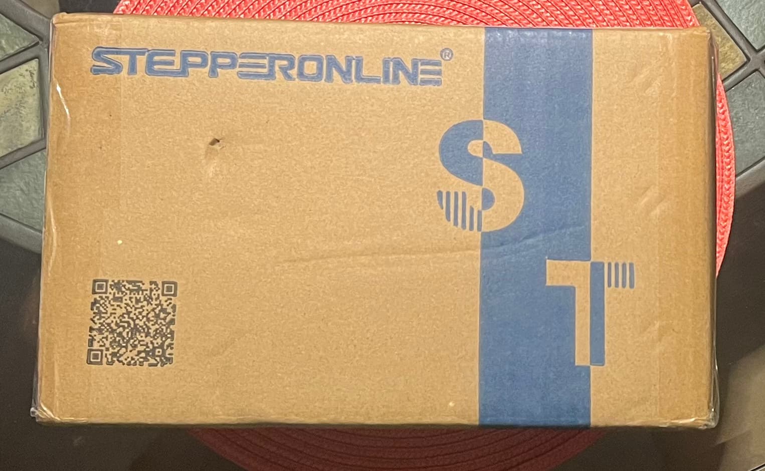
Well, I’m still debating. This arrived from China. Closed loop stepper controllers. I was going to outfit X and Y on a LR4 with these, and I bought some spares. Not sure which way I’ll go.

I’m also still thinking of having modular, interchangable controllers. One thing experimental that will go in this build is an…
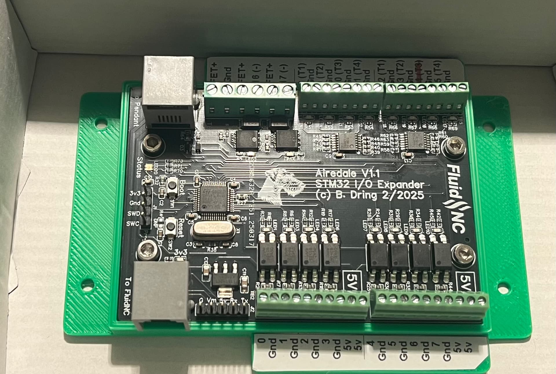
Airdale.

It is an STM-32 FluidNC UART-based IO expander. What does that do? It lets you attach multiple UART peripherals (Like a FluidDial pendant or a CYD), but also adds multiple additional IO channels to an existing FluidNC system.

This is going to go on one of my spare Jackpot boards for experimentation. A jackpot with one of these could support LOTS of additional IO that isn’t really suited to the existing IO coming off of an ESP-32.

The Airdale has a cousin that should be coming as well, it’s a slightly different breed. If it works like I think it will, it will probably sway my decision about whether or not to use closed loop steppers.

Some notes for myself:
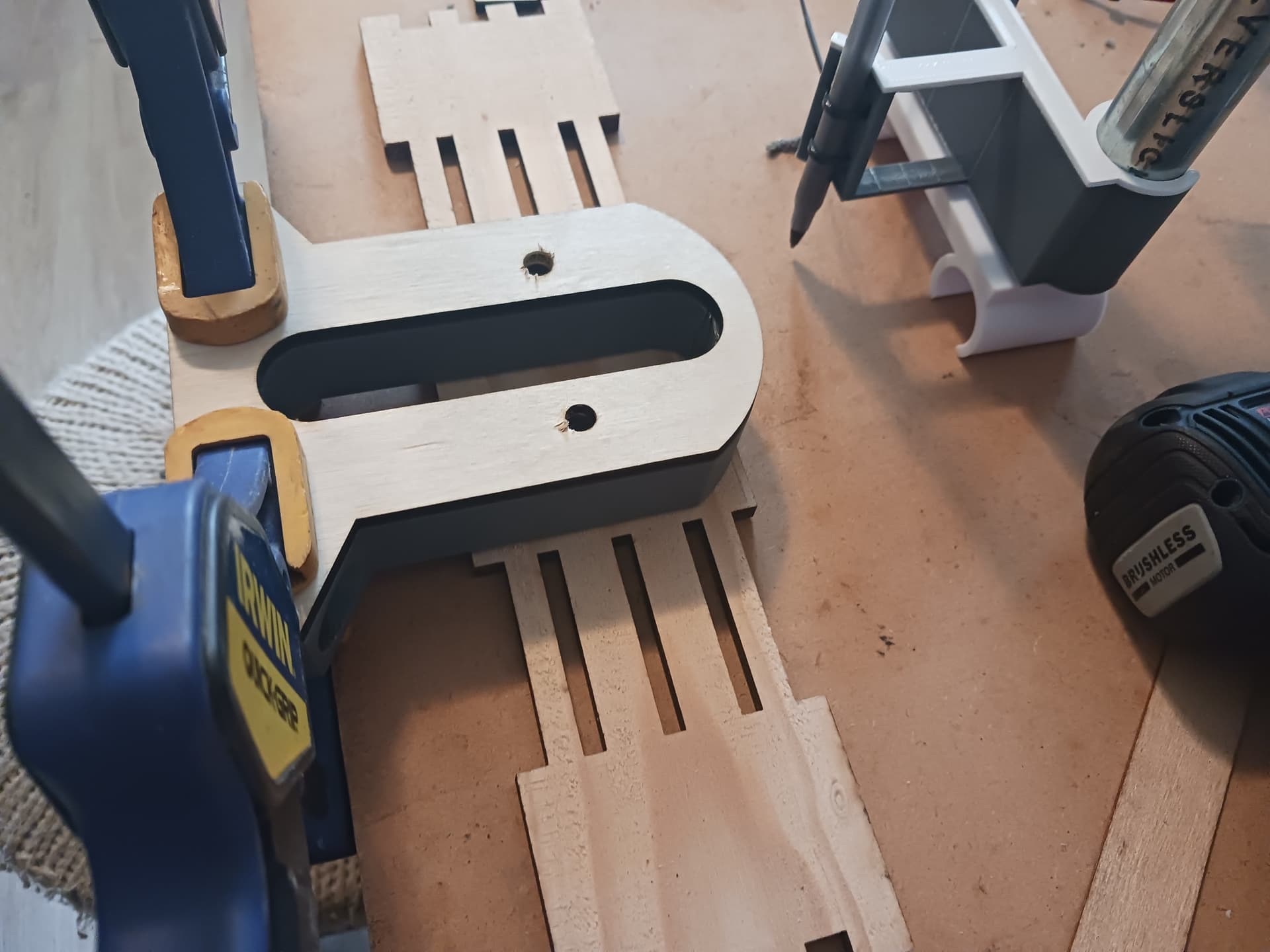
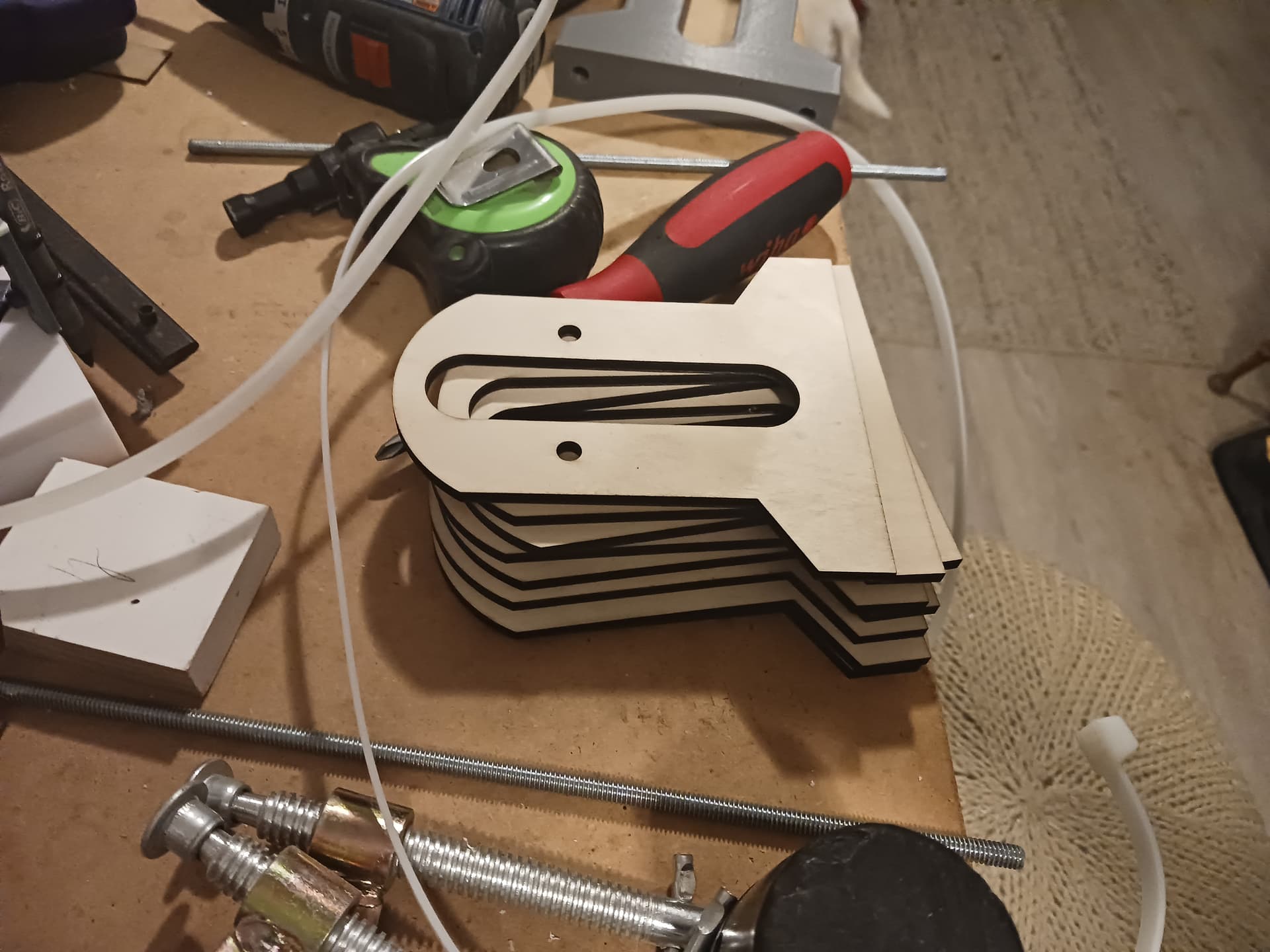
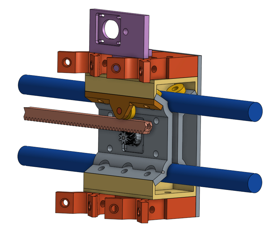
I have printed 40 and 20 tooth rack. If a 10 tooth rack were part of the file set, then one could do an arbitrary length of rack from 10 tooth up in incrments of 10 tooth at a go.

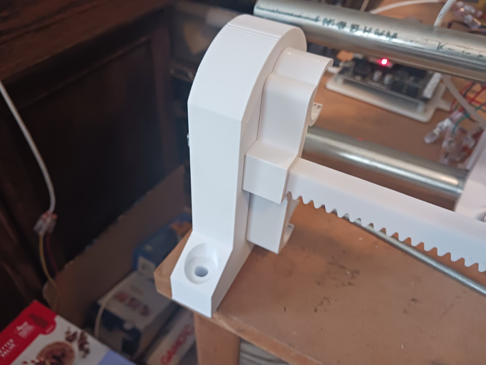
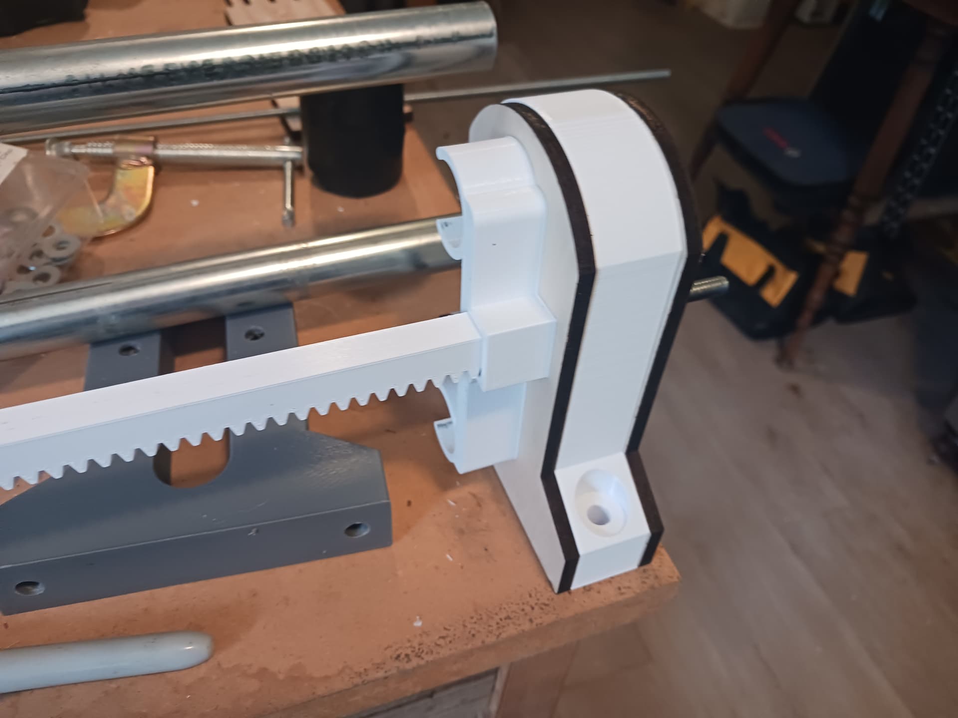
I continue to be impressed at the more reasonable sizes with the stoutness of these printed axis skeletons.

I had some fiddling to do to get the “non-pointy” side of the printed rack to fit the rough (supports side) of the clip. Mostly an assembly knowledge limitation on my part.

Edit: one other thing I thought about: If one were to get really silly and stack long lengths of the printed rack together, a variant of the clip that could help keep the rack from bowing out would be darned useful. I’m putting that back in the thinking step for now.

3 Likes

Those colors are great! I love it. Though not strictly a V1 machine, it’s plastic, skate bearings, and conduit… and done up in V1 colors, I think it’d really look sharp. Portable to boot and modernized with the latest controller(s)… a great test-bed.

I’ve just been piddlin’ with mine today… got the slotted-supports all done up. Now playing with wire-management. Had an idea of using giant 4’ zip-ties in lieu of tape-measure or cable chain… looks a bit dorky, but seems to work better than anything else I’ve ever tried.

Still not real happy with the Z-axis but good enough for laser and pen. It probably needs a modified LR4 for a gantry to be good for anything more.

Here’s a 10-tooth rack section…

MPR&P_rack10.stl.zip (10.9 KB)

3 Likes

My build will likely end up a testbed machine where I experiment with controllers. way more utility than a bunch of parts scattered on a bench.

I’m still thinking about this.

Questions: The axis segment is really clever. You can assemble an axis “motors in” or “motors out” (e.g. just flip an axis 180 degrees around.). would there be more clearance for X and easier cable management if all of this were “motors out”?

Cable management probably would be easier… again, cable management isn’t my strong suit. I’m really wanting to see how you do it. The best cable management I have on any machine is that little $79 JL1 machine with the cable chain. But I didn’t have any in my junkbox and I didn’t wanna take time to print anything more than I had already come up with. I turned the “R&P out” thinking that it would be more protected from chips and debris should it ever be used for that kind of thing.

1 Like

Ooh that’s a good point.

1 Like

If you manage to do Y, tell me how you did it… :stuck_out_tongue: The problem is that the closed-loop steppers that have the same torque are 2cm higher than the other ones. I’d love to have closed loop on Z, that’s the axis that I’d like to make faster than 2000mm/min so I can use the round tabs in Estlcam with faster cuts as well… :slight_smile:

Yeah, when I mock these up it appears I’ll need to print new plates. I haven’t tried modeling the modification yet

I think I have simplified and improved the Z-axis to make it more rigid by reducing the amount of out-front cantilever. It is more compact and “wraps around” the X-carriage rather than all hanging out front. It removes a couple of parts and modifies a couple of others… a new, smaller, Z-backplate will need to be lasered and the upper and lower roller assemblies are now the same, symmetric, and more beefy. The new Z-axis parts (left) and in place over the X-carriage…

The cantilever has been reduced by 32mm, which should make it a little more rigid… currently (left) and the new on the right.

It should look something like this…

and operate like this…

I’m printing the new parts now. Sadly, it’s a 9-hour print so I probably won’t be able to assemble and fit-check until tomorrow morning.

Here’s the new parts…

MPR&P-Z_backplate-V2.dxf (12.3 KB)

Z-rollers.3mf.zip (276.0 KB)

Later.