This is quite an improvement!
When you’ve at least mocked it up I will plan to print one for the machine I’m working on.
This is quite an improvement!
When you’ve at least mocked it up I will plan to print one for the machine I’m working on.
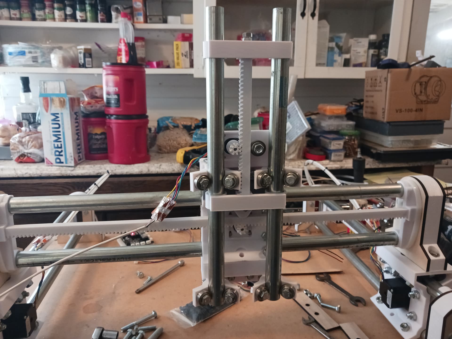
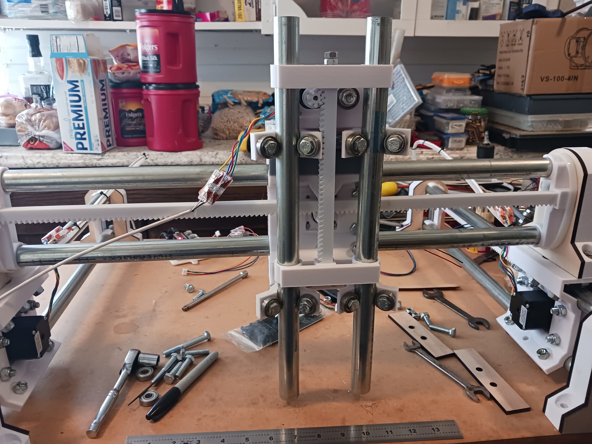
The reworked Z-axis seems to fit and operate as expected… sorry about the shaky video.

The backplate DXF and roller .3mf files I provided above are good. The new roller parts probably could be simplified so they wouldn’t take so long to print or a simple transition piece might be made to allow using the old roller pieces… but I went the most straight-forward way to minimize the number of parts; i.e. the big new roller parts replace the previous ones.
I hope you have a good assortment of bolts… there will be interference and/or assembly issues if you have over-long lengths in some places.
Later.
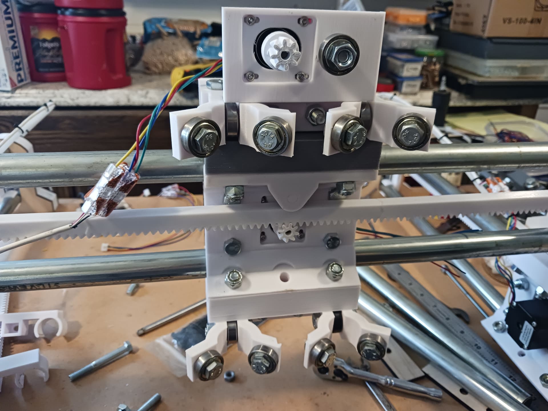
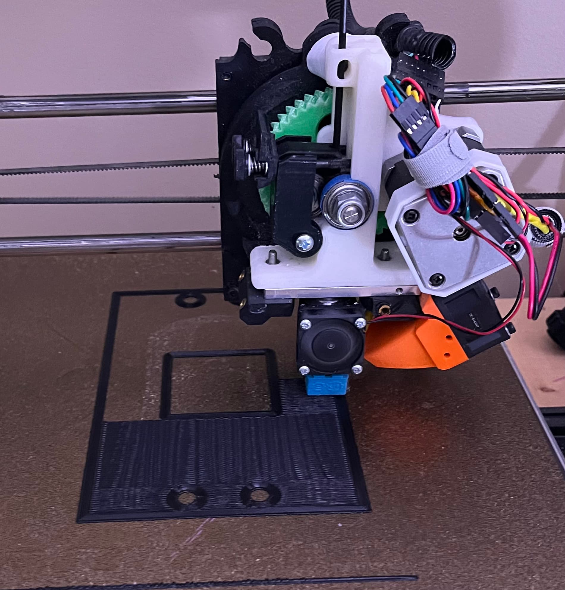
Wiring looks crappy but is out of the way… wanted to see if giant 48" zip-ties from Lowes are stiff enough to do a fake “tape-measure trick”. The new Z-axis is far-less out-front cantilevered so should be a bit more rigid. Moves are very small… it’s air-milling one of Jamie’s rulers from his test pattern generator.

Another view…

Sorry about the shaky video… did it hand-held to try looking at more points of interest.
Woo hoo!
Lets get that pen on there and see a ruler!
Or a laser module mount!
I’ve been down a bit of a rabbit hole, playing with controller mounts, fiddling with ideas for endstops, and generally not having a whole lot of evening time to build.
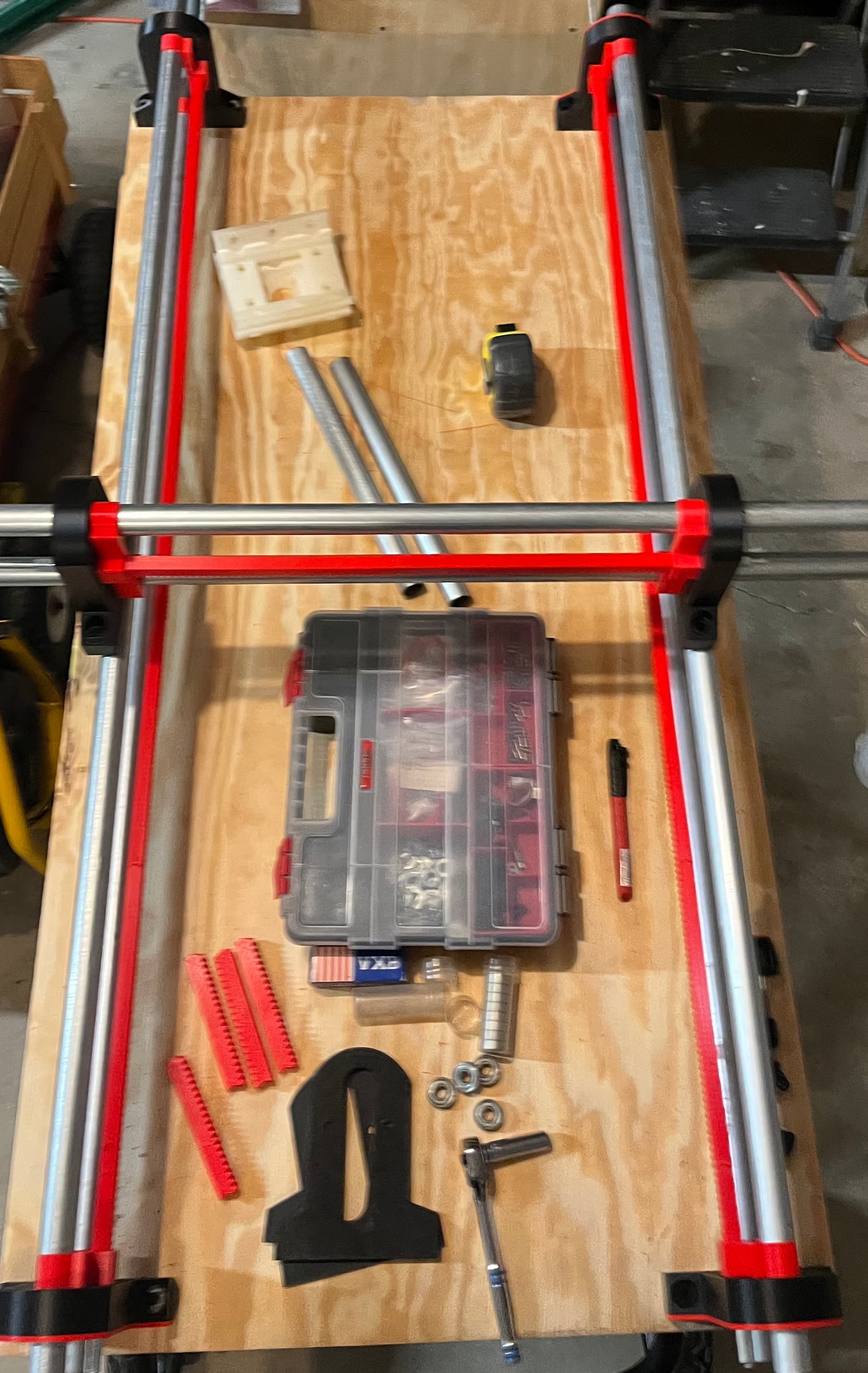
I did find a sheet of off-cut ply in the corner pile which was just about perfect for the mobile bench, and when I test fit a mock-up…
I think that will work. 210 teeth long by 80 teeth wide plus the extra space for everything else. Whatever that converts to.
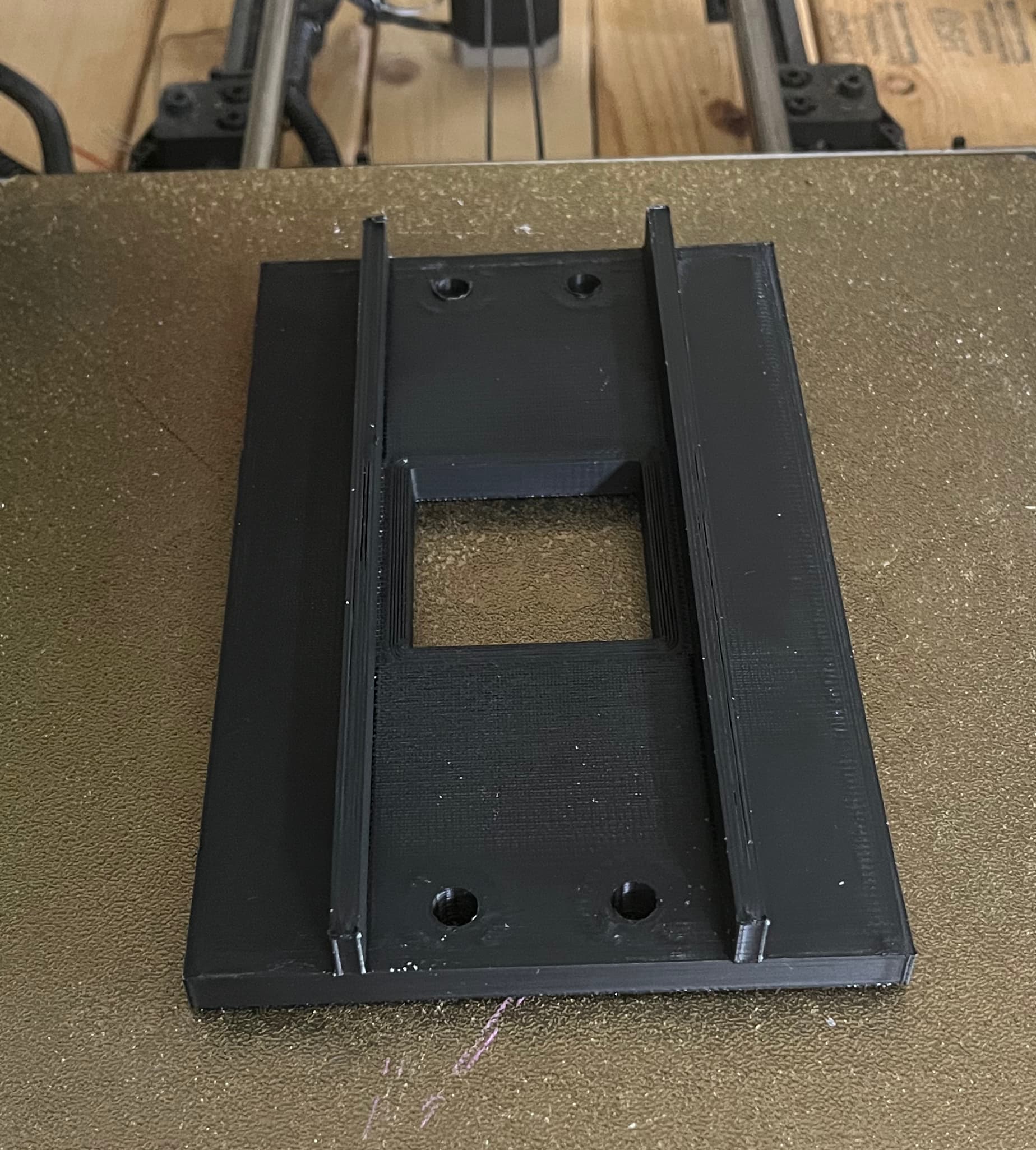
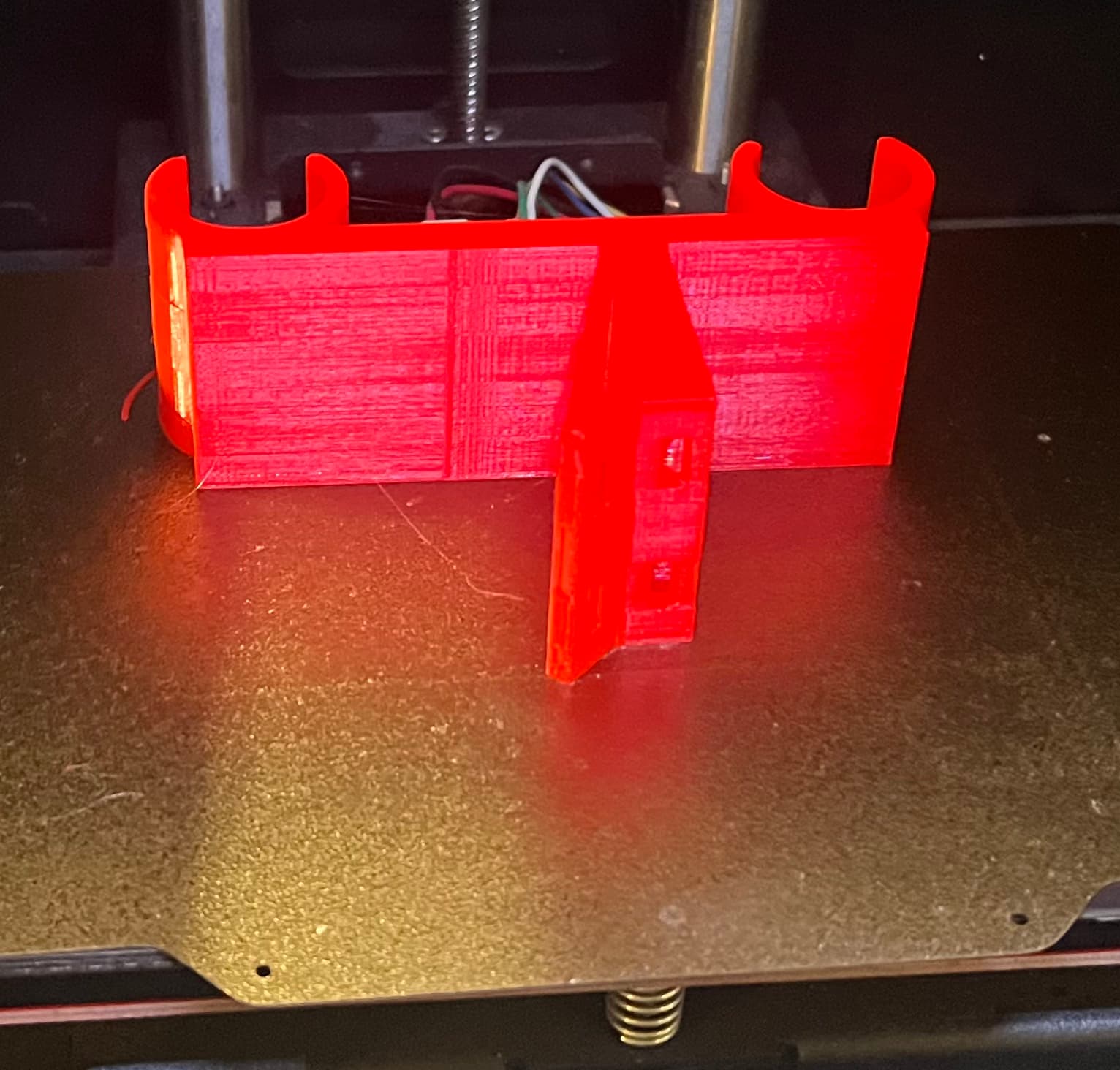
I’m still printing some red endcaps, and I kicked off a print on the Taz a bit ago:
We’ll see how the back plate works when printed. I made a mod to help it out a little bit.
After the back plate prints, I’ll fire off a pen holder mount.
I’ve also been fiddling a bit with the stepper motors, still debating. I have an extra set of steppers from Ryan’s shop. Maybe I’ll just build this up with a set of those…
I also played around a bit with the idea "What if I took the LR4 bauer mounts and cut them into the Z axis here. Crazy idea, I know, but at first fiddle possibly doable.
Does anyone know of any small alternatives to a trim router?
Like a rotary tool that doesn’t have horribly bad runout?
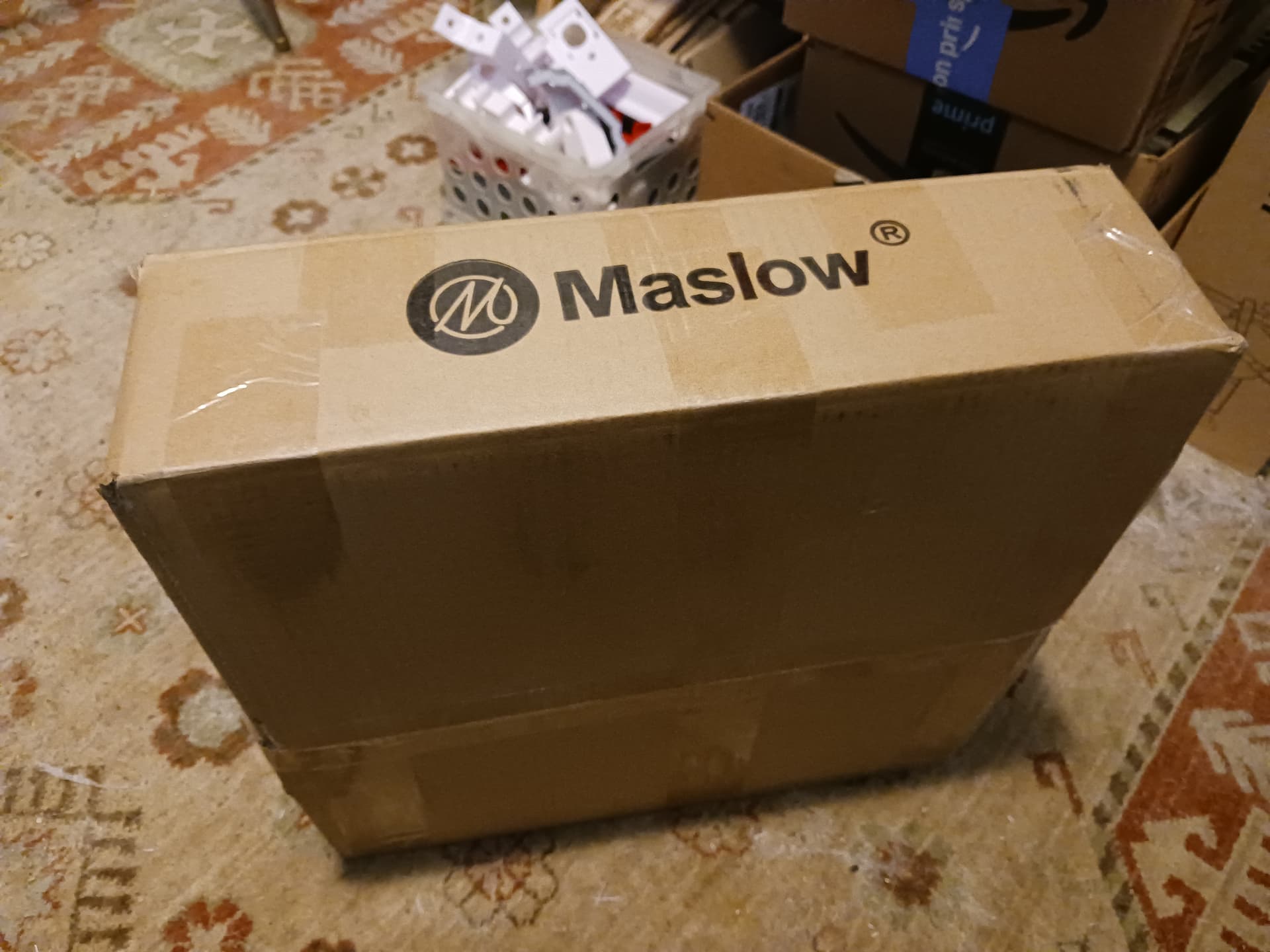
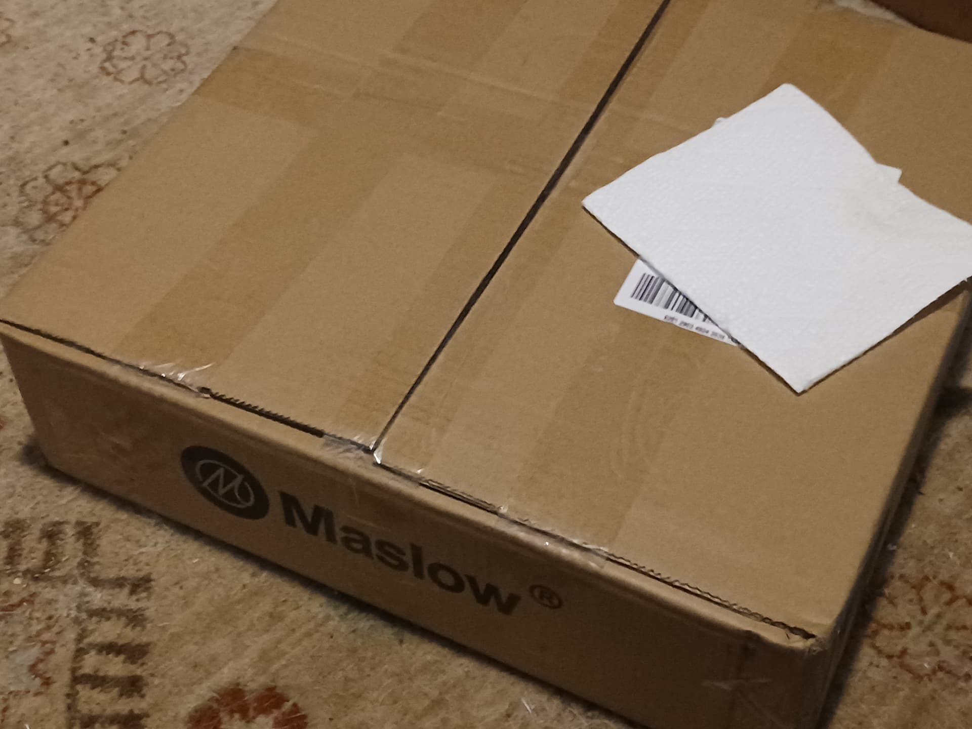
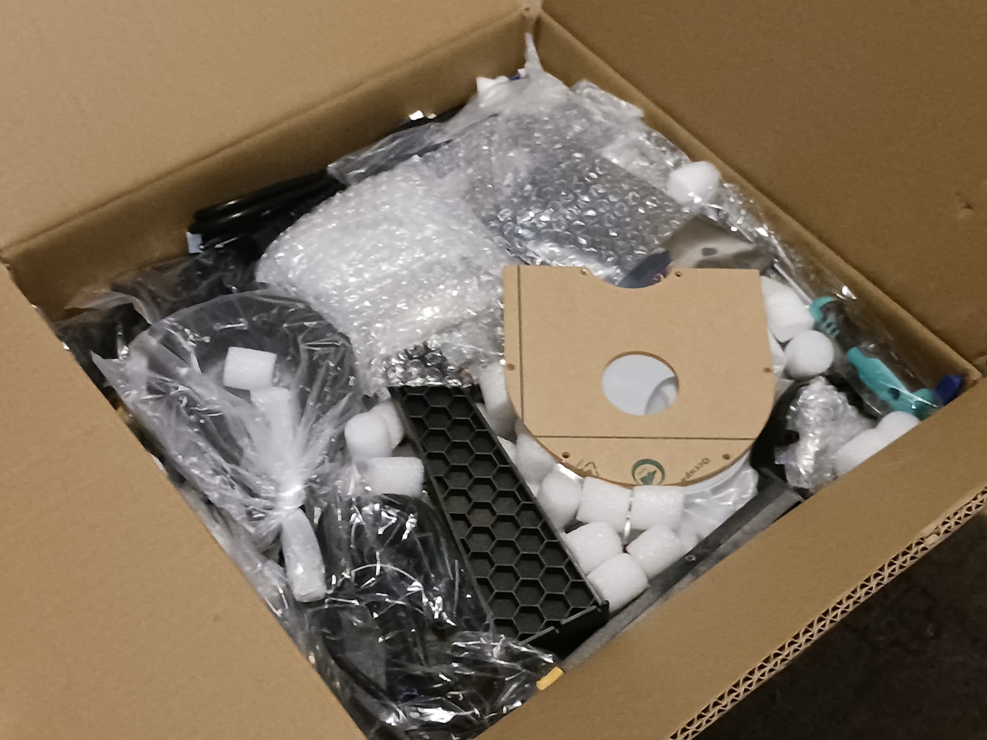
I suppose timing is everything… lookee what showed up at my house a few minutes ago!
SIL has limited interest in CNC except for something big and strong enough to do furniture-sized stuff… and had seen that someone in the area had an earlier version Maslow for sale. I checked online to see that there is was a later and more capable Maslow 4.1 available for pre-order and told him that, for the money, I thought the newer one would better suit his need. I told him I would be willing to get it and help him get it set up of if he’s serious about it. It had just finished the Kickstarter promotion but could be preordered… so I ordered it. And then, in no hurry, knowing all the Kickstarter supporters would be first in line… I promptly forgot about it. Apparently a giant number of full kits were on the last ship from China to arrive and unload before the tariffs kick in… and mine was among them. I think they have suspended pre-orders for now… until the shipping uncertainties settle out a bit.
Since Maslow 4.1 can be operated horizontally and anchor points need only approximate location… it looks as though it could easily be set up on their deck for operation and then the cables disconnected and retracted after the job completes, for storage.
Looks as though it could be fun to play with…
Later.
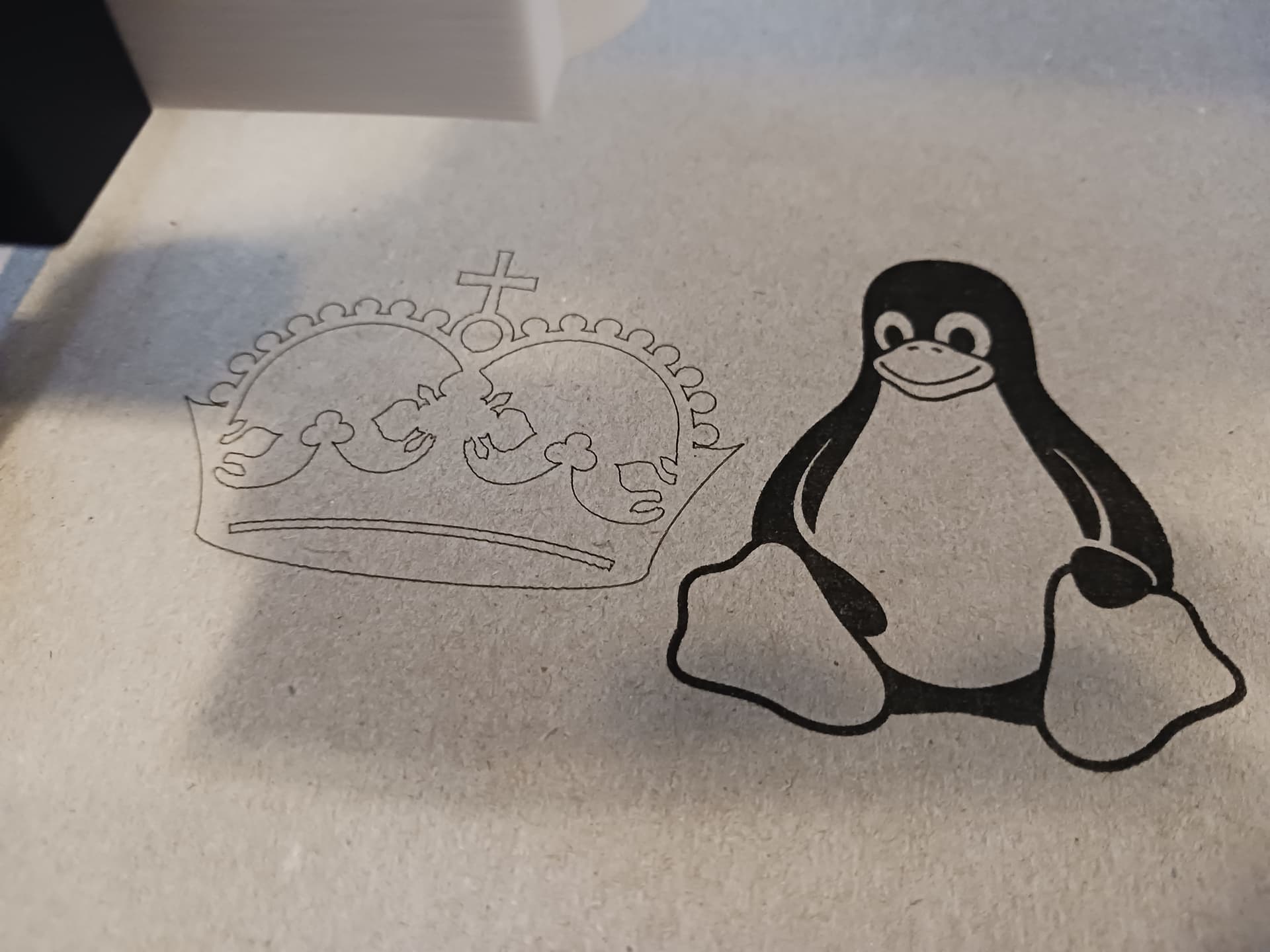
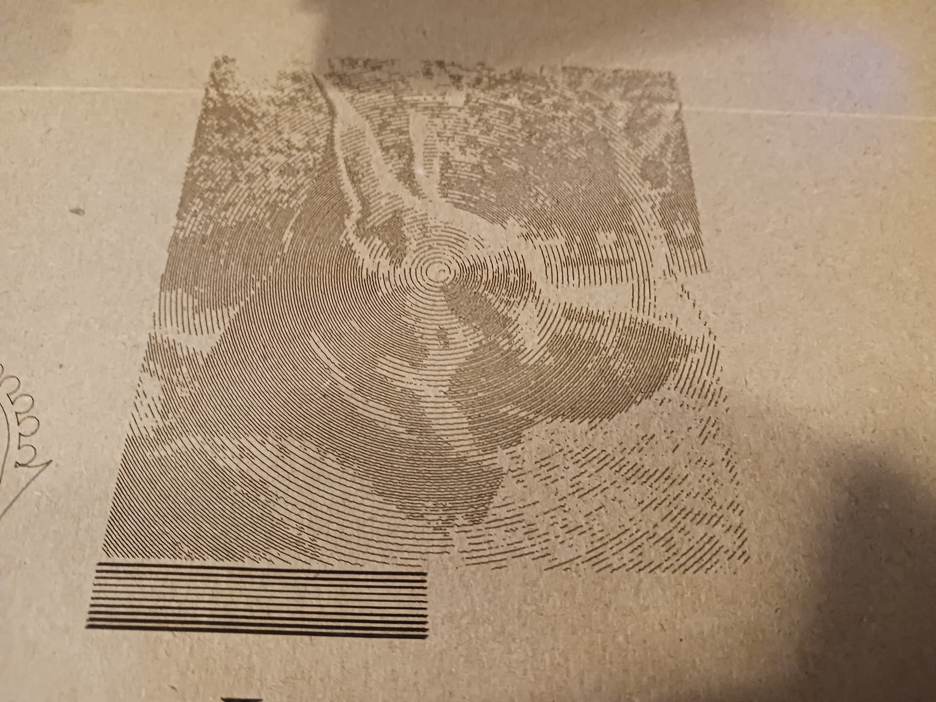
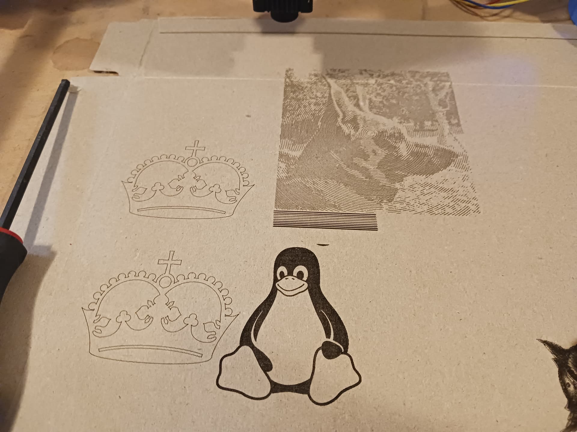
But my MPR&P is fun, too! Blackstripes stylized spiral artwork… my dog Mac has style!

Note Ryan’s focus script… in action! A blast from the past!
– David
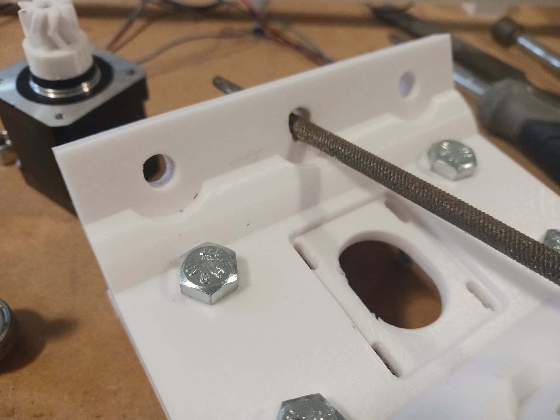
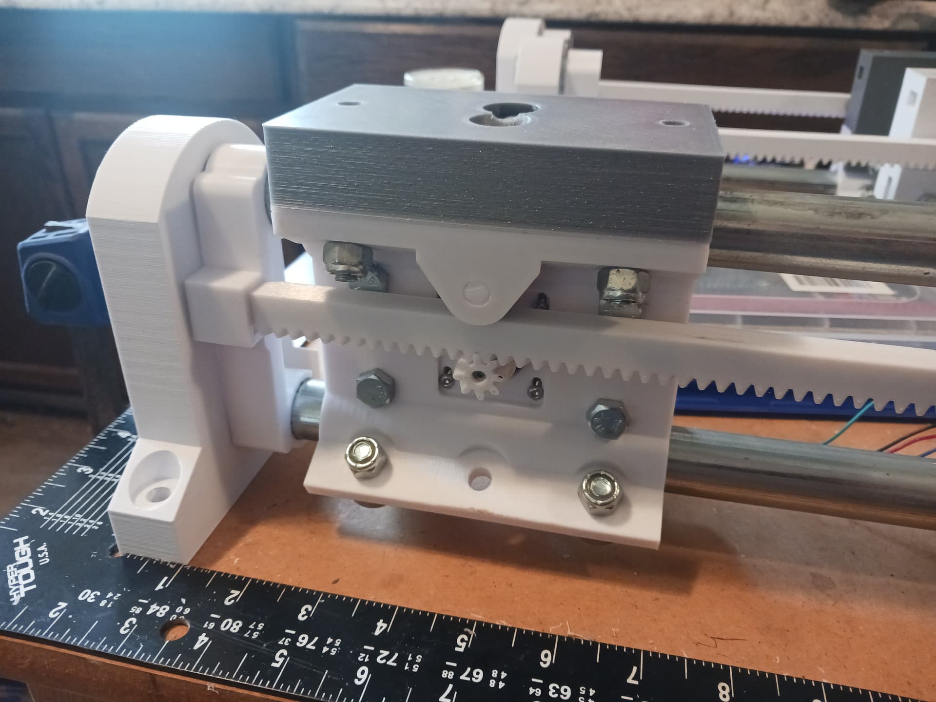
Friday I did some more mockup assembly. I’ve had a bit of difficulty making parts fit as the bolts I’m using are all spare from LR4 beta builds, and they’re not really sized correctly for this.
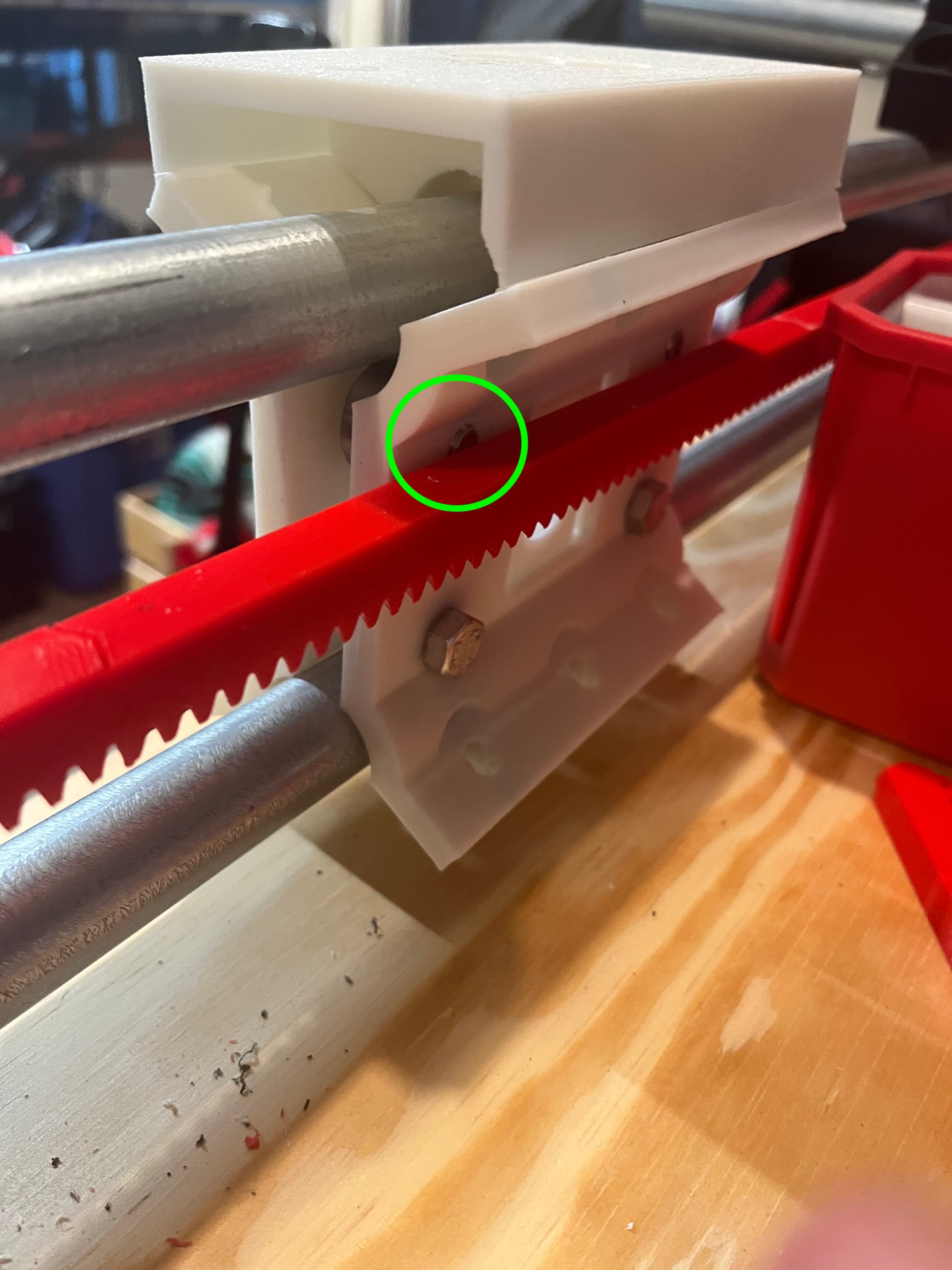
Below you can see some of the mockup, this deliberately with the bolt in the upper left the wrong way round to explore clearance. This was still very crudely assembled, but it made clear that the spacing is really tight in this spot. It appears to get this to work, the carriage needs to be assembled before the rack is installed and end caps put on. On my machine, when more fully assembled, there’s an bit of interference between the bolt head and the rack when the carriage is at either extent of travel of the axis.
I’m going to go find some button head hardware in the right lengths to continue assembly this weekend.
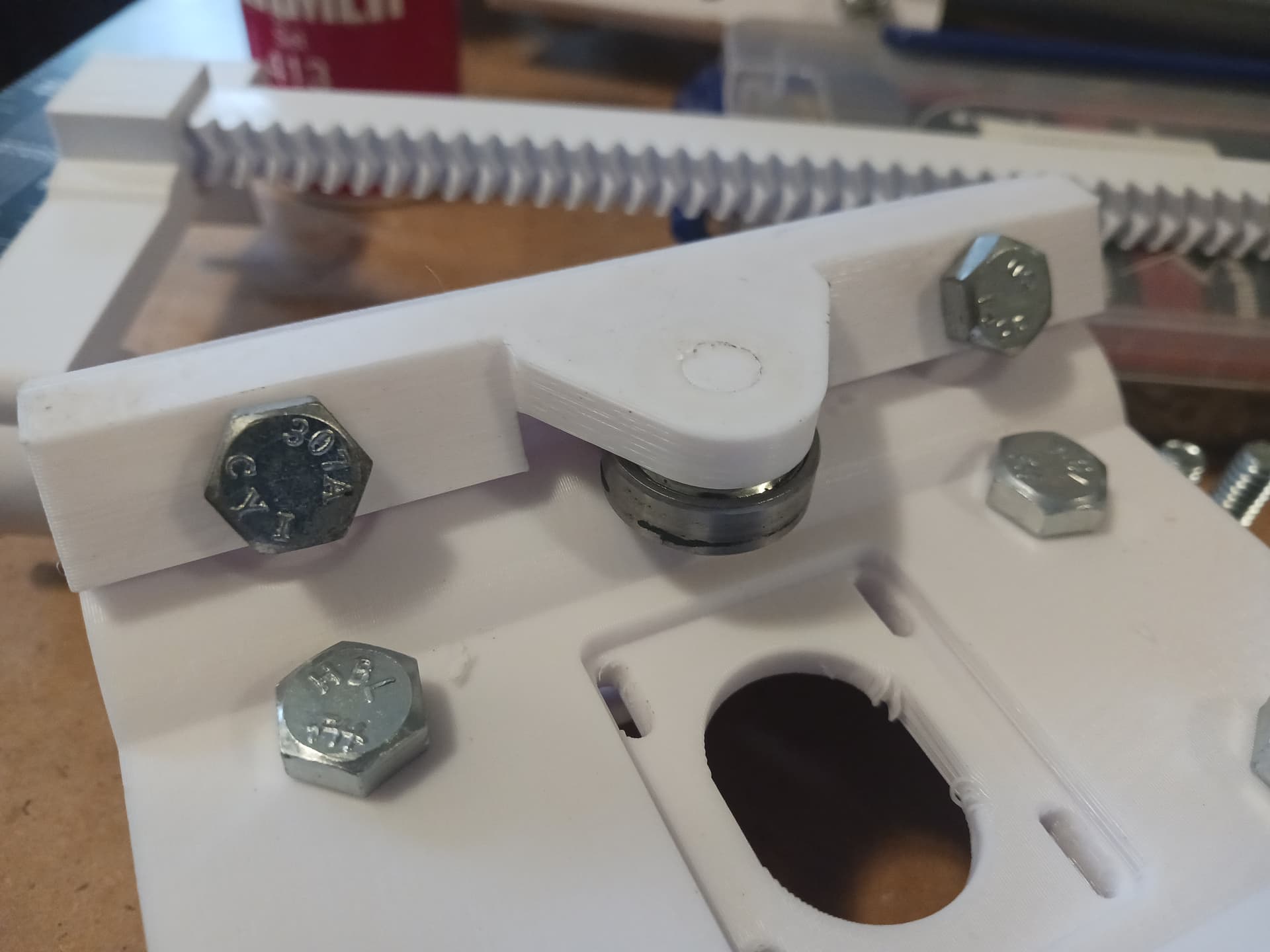
I eventually got far enough along in mocking things up to have a sense for how to assemble tihs.
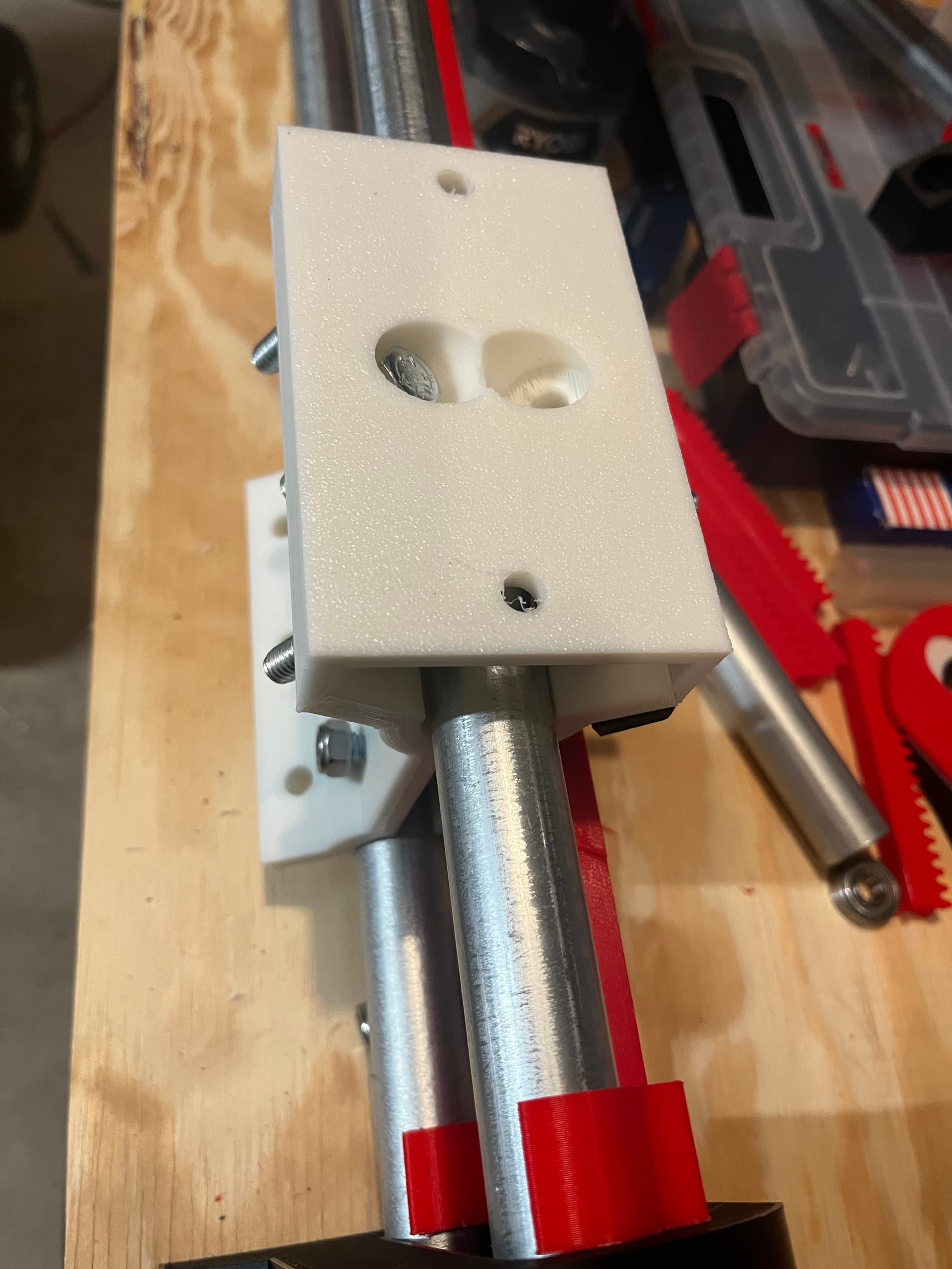
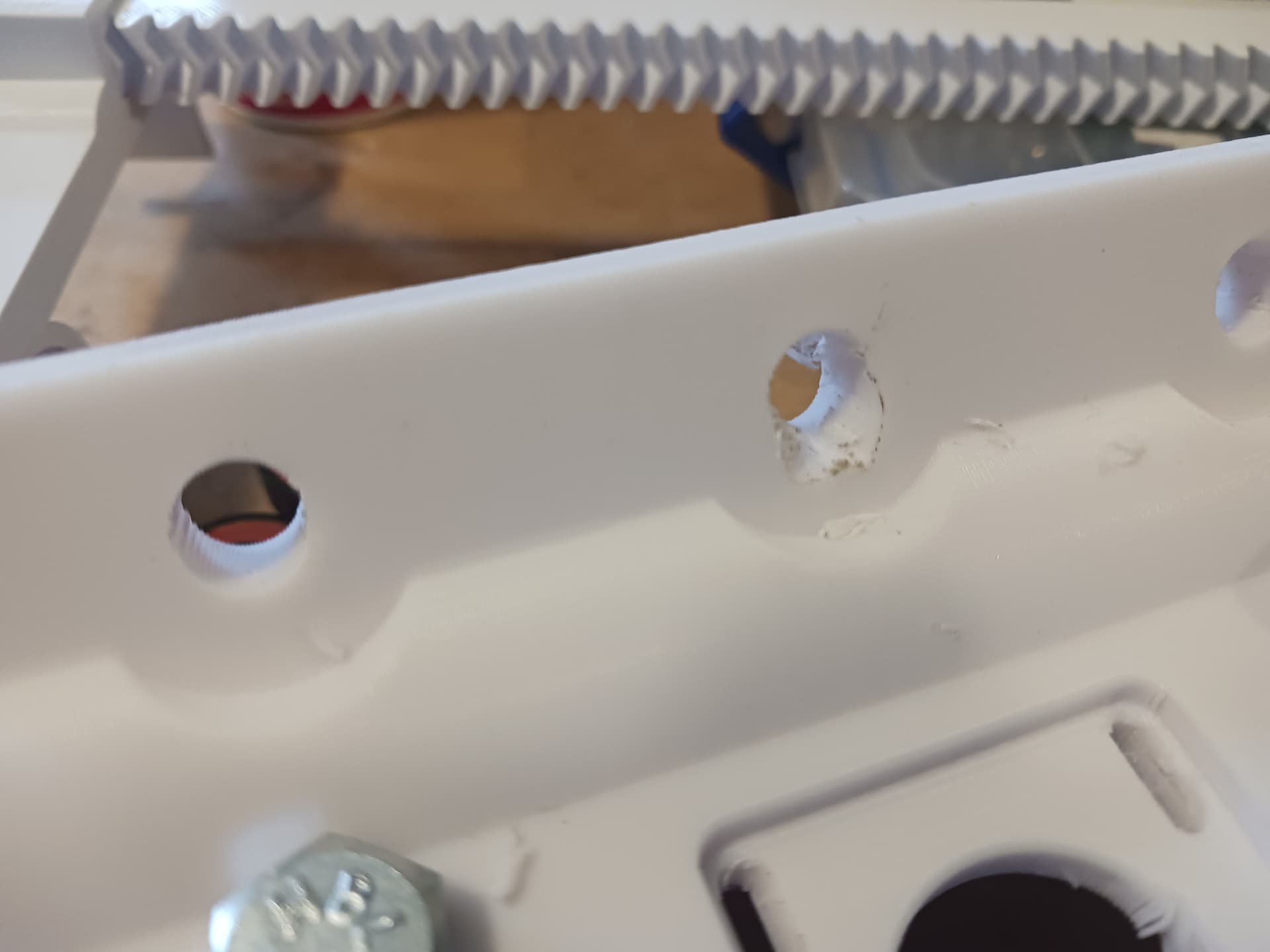
One question I have is about the pressure pins in the bearing that rides on the rack. All of the pins I printed snapped, which means the orientatioun I printed them is just wrong, but further I’m not sure why that bearing isn’t just retained with a button head screw from the inside.
I’ll be fiddling with that a bit more as I go this weekend.
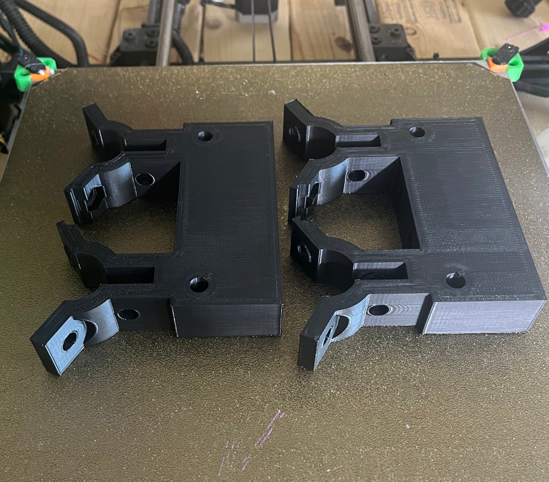
The larger of the new Z parts were printed yesterday and If I get to the point of assembling a Z axis I’ll report on that. I added a pair of stiffeners to the printed version.
Certainly not mass-optomized, but they feel very stout.
This reminds me to kick off a pen holder from up-thread as a print. I’ll get that running shortly.
Yep… they’ll snap if printed on end. I printed them lying down with “support from bed only” so that the “grain” of the plastic runs the length of the pin. I printed a bunch of pins separately with support and have plenty of spares…
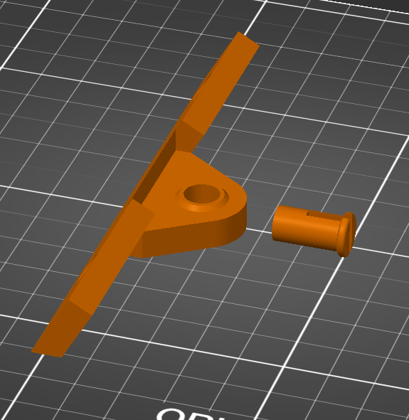
Clean-up of the pins wasn’t difficult at all… I use a sharp straight blade knife to scrape any support cruft off the pins… fit on the bearing from the little end up to the “knob” and then tap/press the pin and bearing into the mount. The slot in the pin is unnecessary (initially the pin and mount were one piece) and I didn’t have button-head screws to test fit. The plastic pin should be fine for a slow-moving pressure bearing and the clean backside/outside of the bearing assembly when installed retains the flat outside surface of the whole carriage assembly.
Tiny bit of clearance needed for pressure bearing…
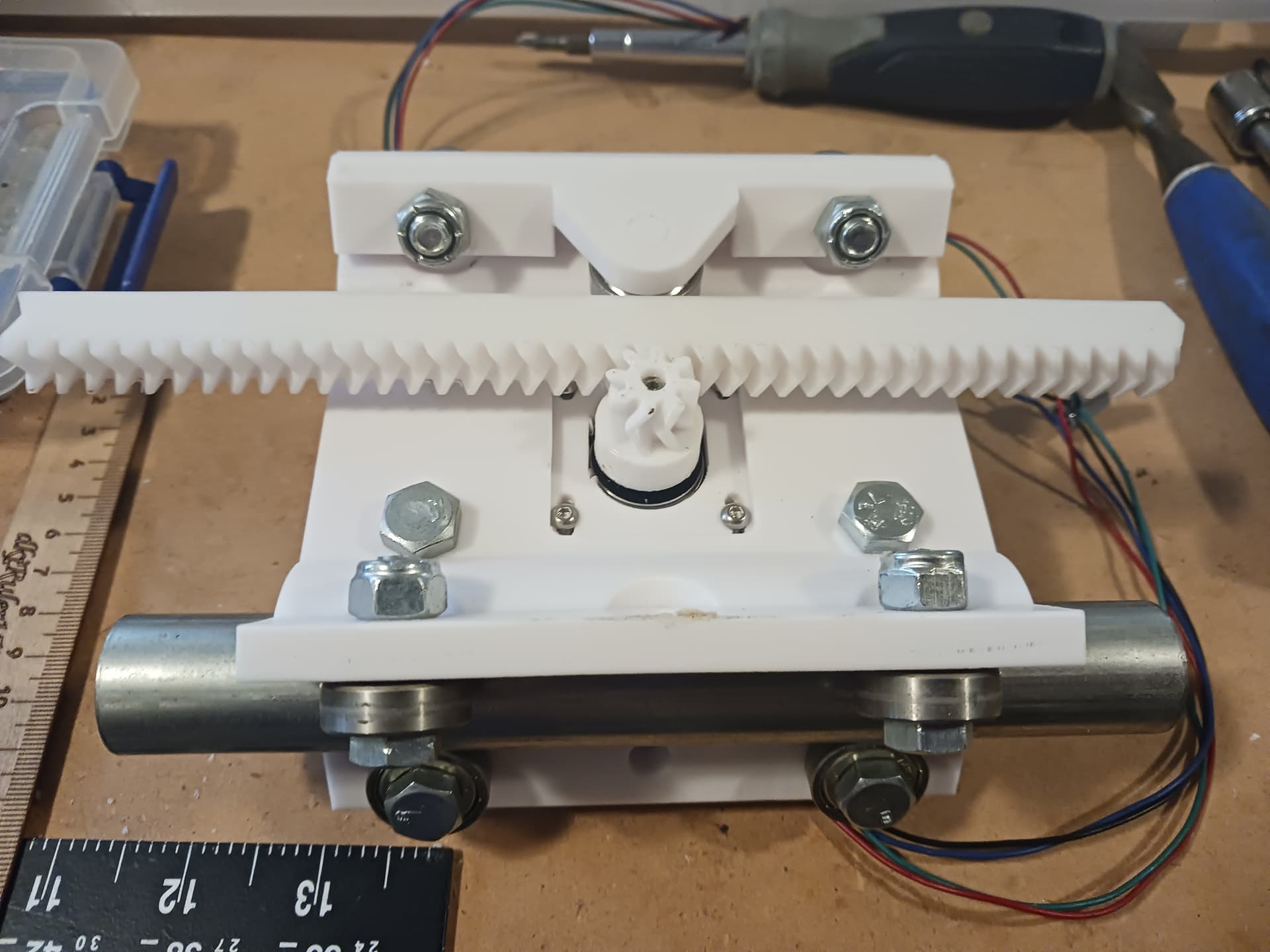
All the junkbox bolts for my MPR&P are 5/16" (8mm) hex from Lowes and Bolt Depot(?) online… of various lengths, but mostly shorter (< 1-1/2"). Each carriage has 4 bearings between the carriage halves, 4 each on top and bottom flanges of carriage, and one pressure bearing… for a total of 13 bearings.
I like the printed Z-backplate with stiffeners.
Holler with any assembly questions… I have lots of photos.
– David
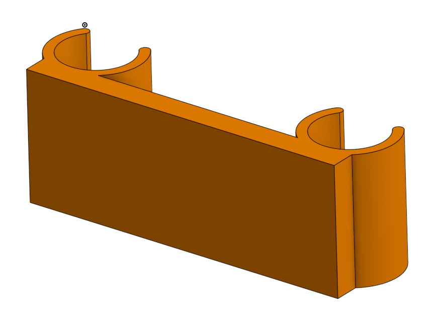
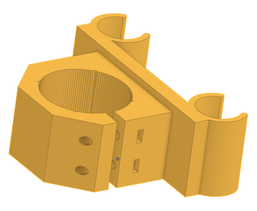
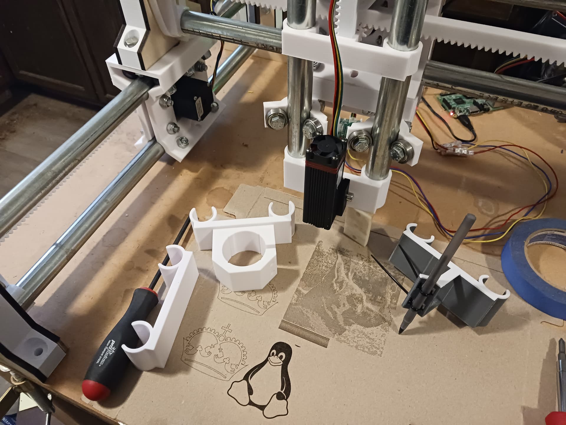
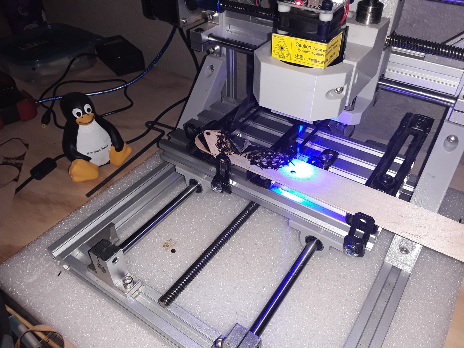
An assortment of tool mounts… blank, Neje laser, pen, and 775 motor mount.
In reality, I suppose these should completely surround the conduit in a clamp configuration… similar to the 775 motor mount. But for very light loads the snap-clamp seems sufficient and convenient.
– David
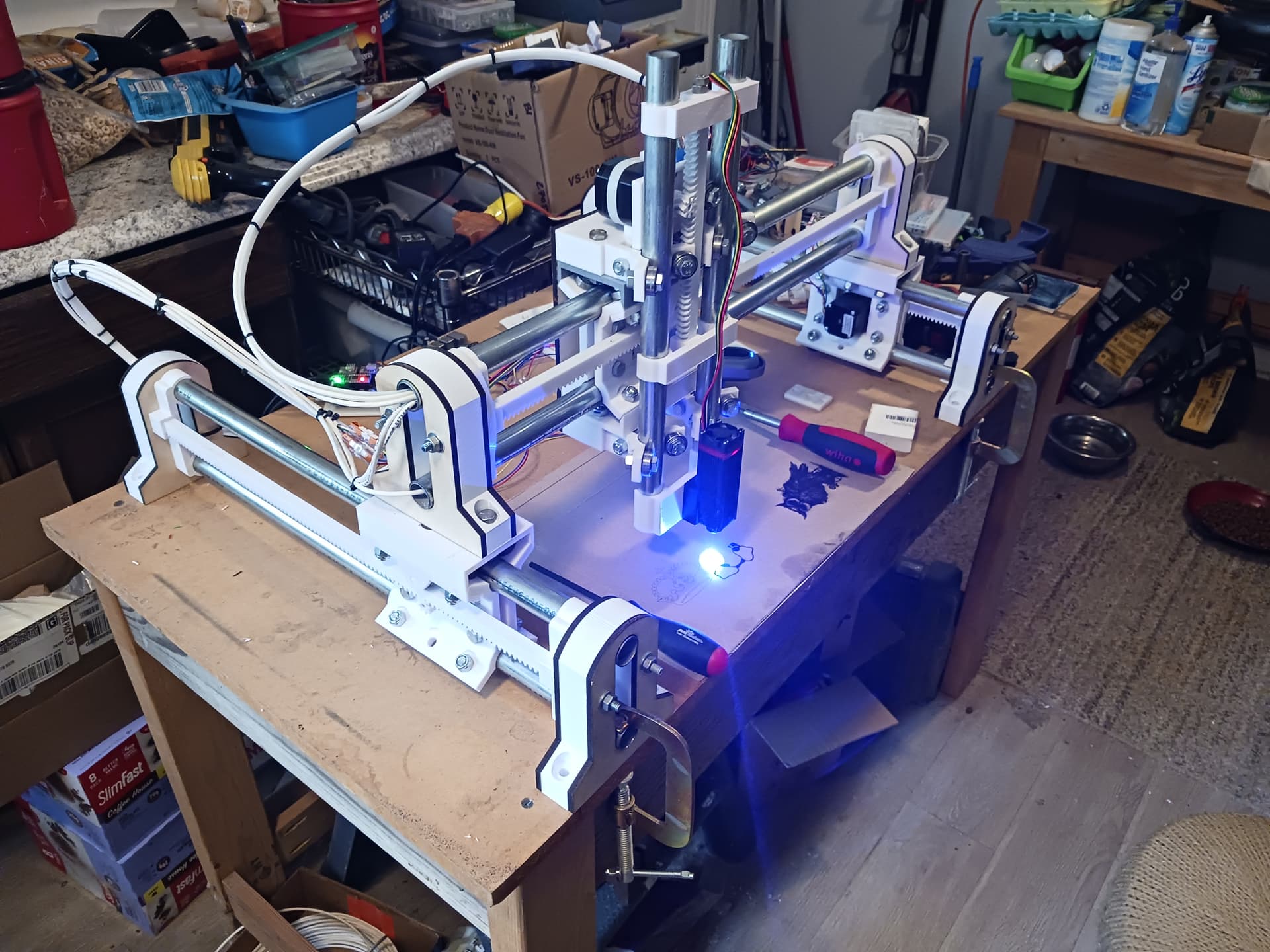
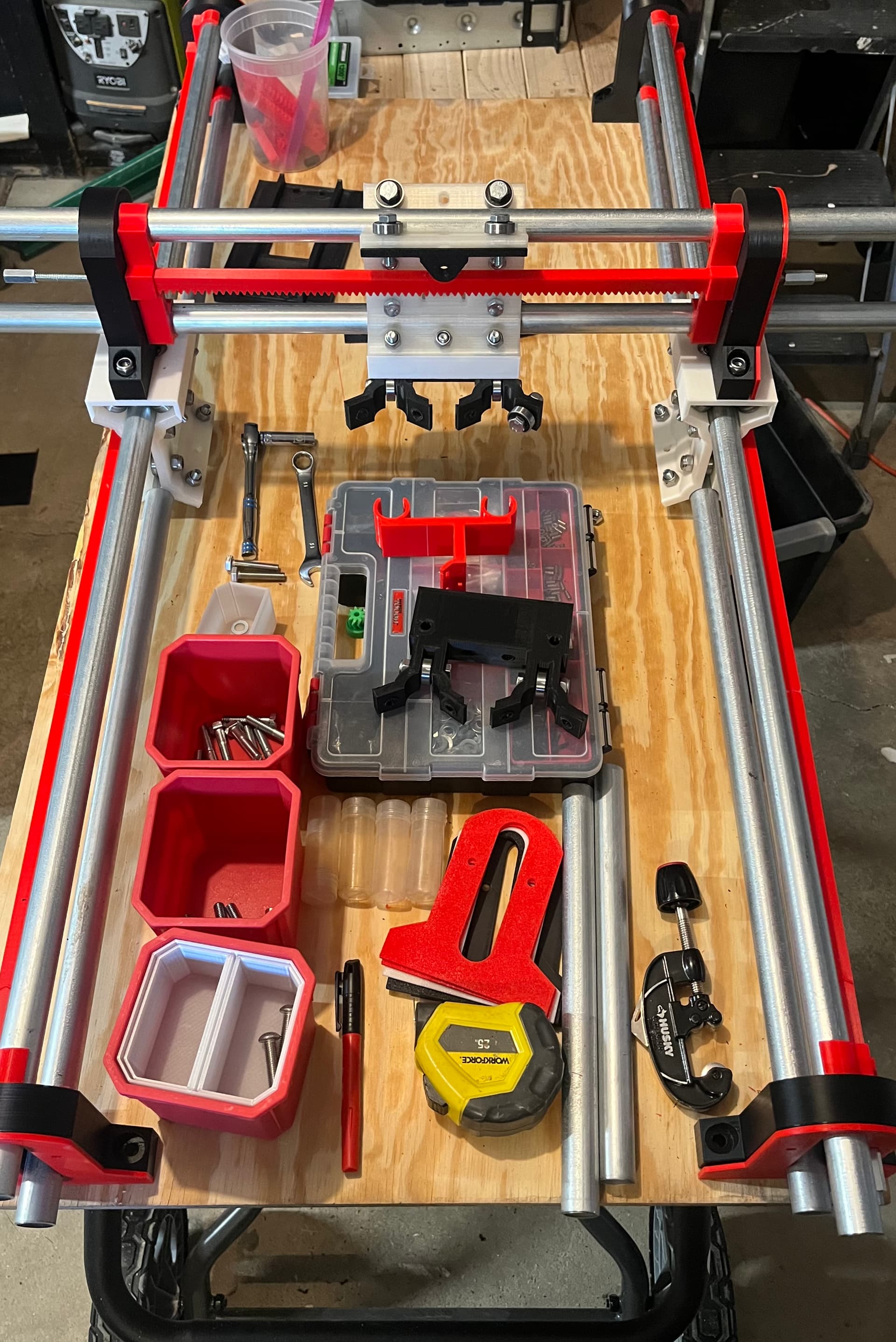
Made a fair bit of progress today. It’s starting to look like a machine!
I’m really scrounging through the parts bins now as I’m in need of about 4 more bearings to finish the Z.
I have a bunch of Z axis parts printing now, hopefully tomorrow I’ll have the mockup assembly done.
Still fiddling with the pins for the pressure bearing. I hope to fire off a test print of my own version sometime late today or early tomorrow.
Still also fiddling with controller box ideas.
I really like those latest mounts.
I have some 775 motors, it’s really tempting to try one.
Are you going to post them?
I’ve debated mounts that use a wrap around clamp and am still noodling on that. This looks completely fine for pen/laser/drag knife use. I start to wonder with the 775 mounts whether it needs better retention.
Machine motion is great, very solid machine. I am going to add fender washers to the 1/4-20 rod clamp points, then will tighten them all up “for flight” ![]()
Pen holder is ready to go. iPhone refuses to take a good picture of this filament while in the printer under its’ LEDs.
If things go really well maybe it’ll be moving in the next day or two.
I’m doing some more thinking about how to better mount this to the portable bench.
I’ve updated the Printables MPR&P model pages. I forgot that none of the Z-axis stuff was out there yet… so put the new and improved Z-axis parts out there as well as the new tool mounts.
No doubt the wrap-around clamp is the proper way to go. I just like the convenience of the snap-clamp while doing the development… and since it is sufficient for the light-duty stuff I do, I’ll keep using it. I’m gonna depend on “youse guys” to harden it and make it a real product… ![]()
It looks from your photos that one axis on your machine is gonna be 2X-3X longer than the other… does it really fit on your portable bench with that big a difference in aspect ratio? Oh, that’s right… you said you were counting “teeth,” 210 teeth by 80 teeth! Which is gonna be your longer axis… X or Y? On my machine, X is the slightly longer axis… so, I’m in landscape mode.
I thought at one point that I was running out of bearings (that I could find, anyway) as well… but then I discovered another trove of them. What I did run short on was the proper length roller bearing bolts… so I’ve got some short ones on my machine, holding on only by a thread or two. I’m resistant to buying any bolts at this point… not until I can declare this machine “complete”, demo it sufficiently, and still claim it an “almost completely” junkbox build.
I knew you had a CNC3018 machine or similar, so you have a 775 “spindle” setup for it. So do I, so I figured why not make a tool mount for it? I remembered seeing somewhere a printed tool mount STL for that machine, so it’d be simple to find it, download it, and merge it with my blank tool mount. If this machine was ever destined to have a “spindle”, I figure this is it! That spindle mount also has notches inside the clamp area to hold IIRC a small 30mm x 30mm laser module… and I once used it exactly that way.
I’m anxious to see your machine start moving. I know you have limited time during the week to work on it… so I’ll just have to exercise some patience.
![]()
Look at David knock out a full machine in a few days… it’s incredible.
I haven’t printed this yet but if you want to try it, let me know how it goes…
775-motor_mount.zip (249.8 KB)
I’m going to put that on a printer in a couple of minutes!
Thank you for the kind words, Philipp!
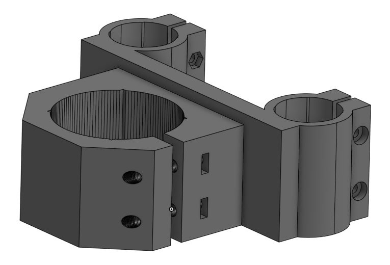
Does that need a counterbore so the screw head can be flat against it? Or is there one that I can’t see.
Uh-oh! That’s the part I lifted… stole… borrowed from this TV model (thanks, @kochmax!). I didn’t inspect it closely and trusted that it was okay; i.e. I just wanted the motor surround-clamp part to merge with my tool mount. I’ve got it in Onshape so will do what I can with it. Sorry 'bout that…
![]()
No worries from me. I’m just an observer.
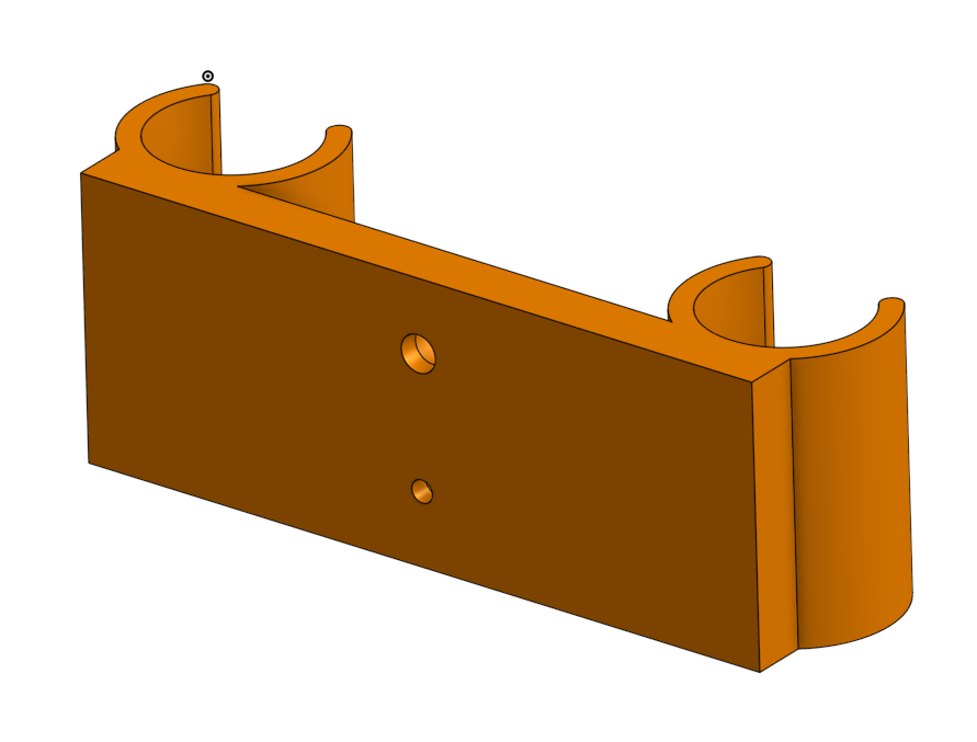
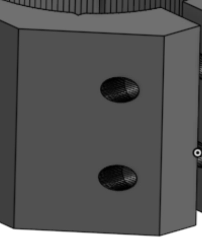
Looks like M4 dimensions on those holes… so added 8mm diameter counterbore.
I should have checked that… and made the same sized holes for the conduit clamps. Instead it’s M4 hardware for the motor-body clamp and M3 for the conduit clamps.
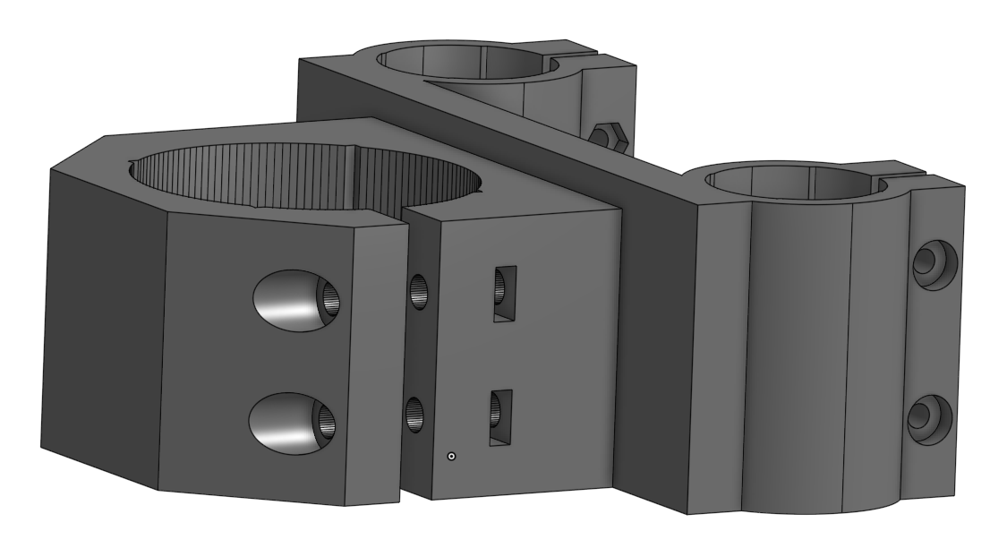
That’s what I get for not actually printing and fit-checking before posting parts. I’m gonna need to print one now…
Sorry, folks!
![]()