Good catch, @jeyeager . @dkj4linux did the part get pushed back to Printables or re-shared here?
I’ve got a bunch of family stuff this morning so haven’t had a chance to kick off a print yet.
Good catch, @jeyeager . @dkj4linux did the part get pushed back to Printables or re-shared here?
I’ve got a bunch of family stuff this morning so haven’t had a chance to kick off a print yet.
Hold off a bit, Jim. I’ve already added the counterbores that @jeyeager caught. But I also wanna look at adjusting the conduit clamps for M4 hardware as well.
I’ve adjusted everything, I think, for M4 hardware and have just started it printing. It’s a 4-1/2 hour print…
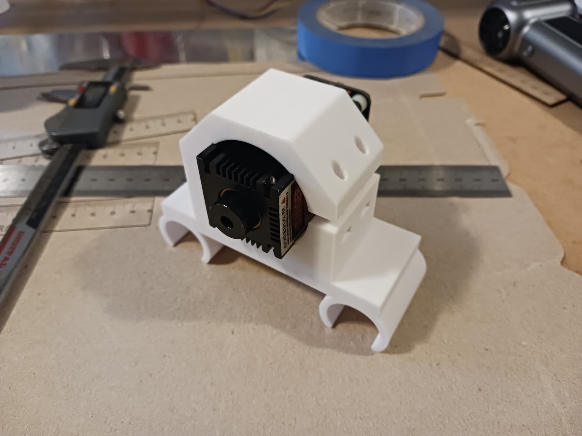
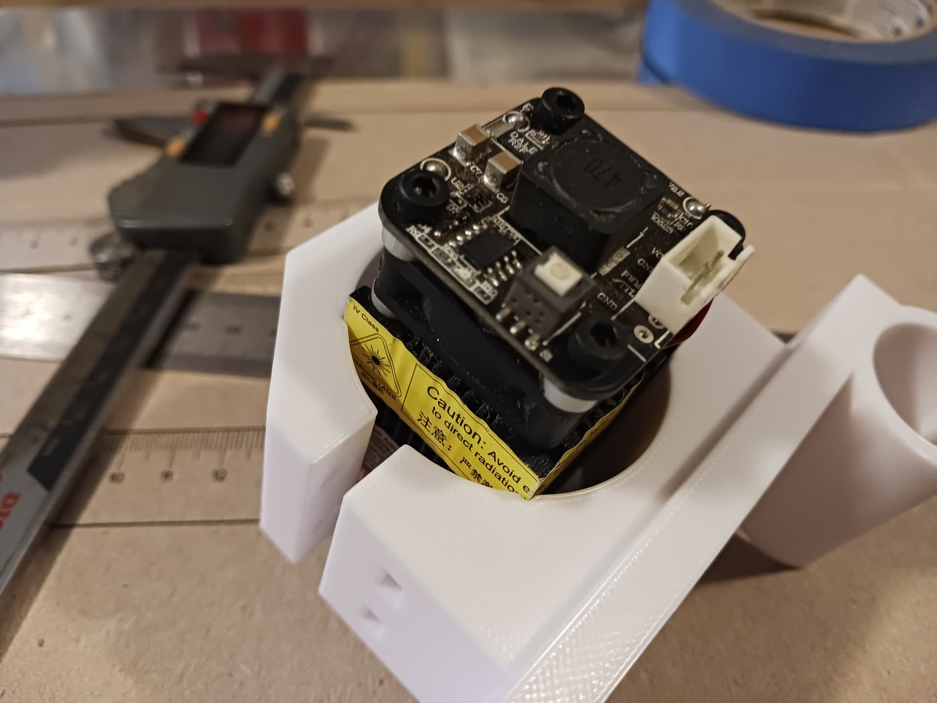
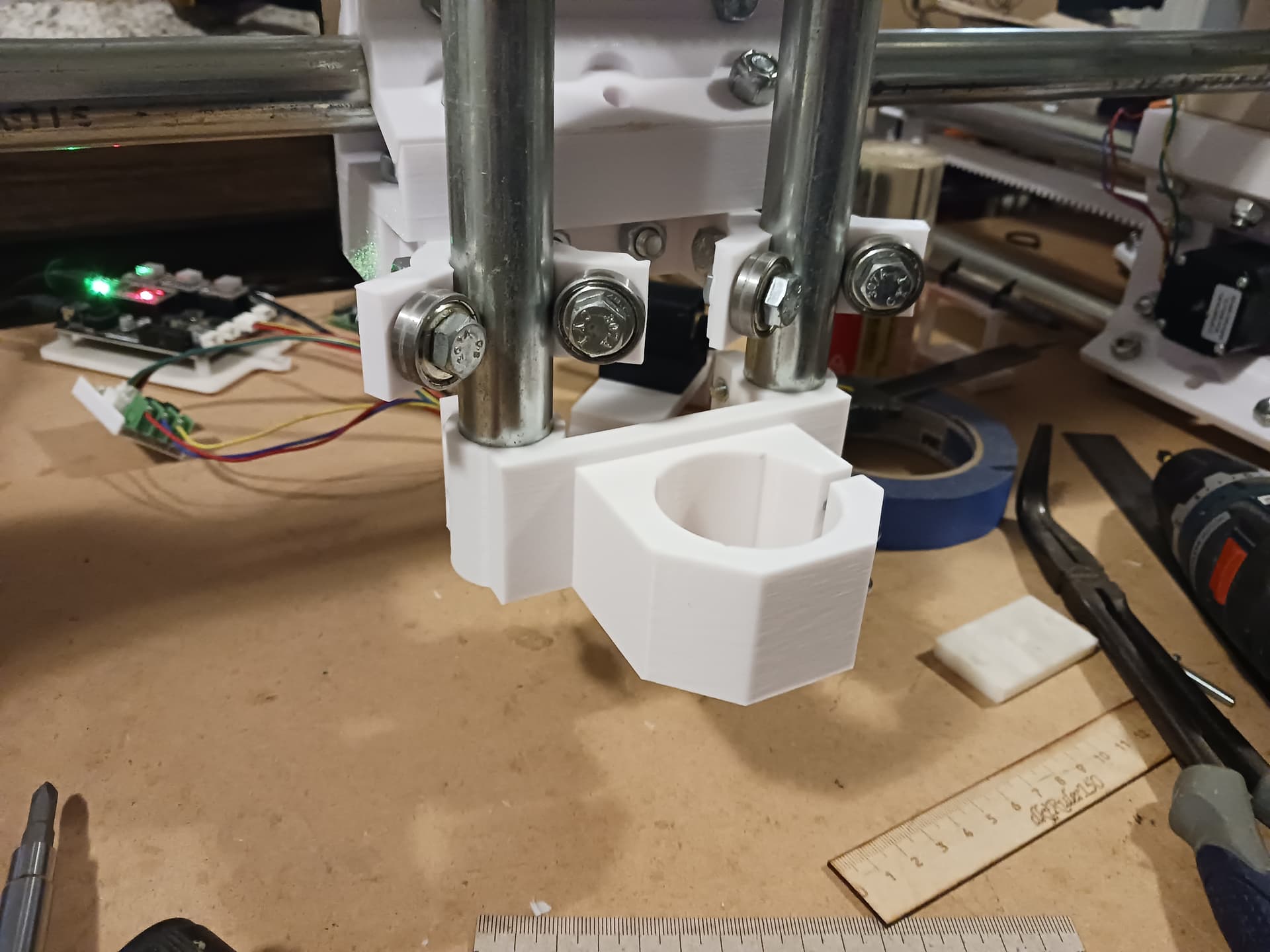
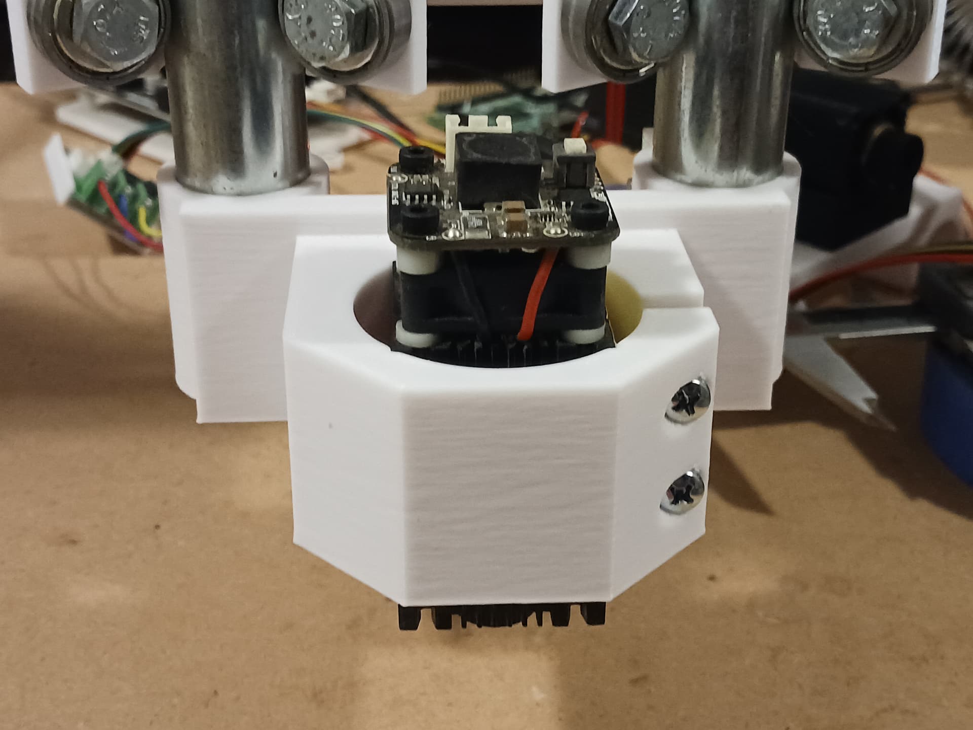
I can’t put my hands on a 775 motor at the moment but the motor clamp with notches for laser seems correct…
If you want to go ahead and take a chance on printing it now, here it is…
CNC3018-775-motor_mount.zip (275.5 KB)
– David
Went on the printer just now.
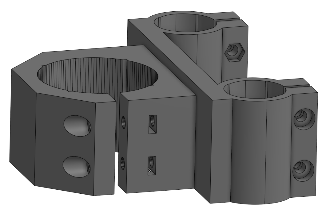
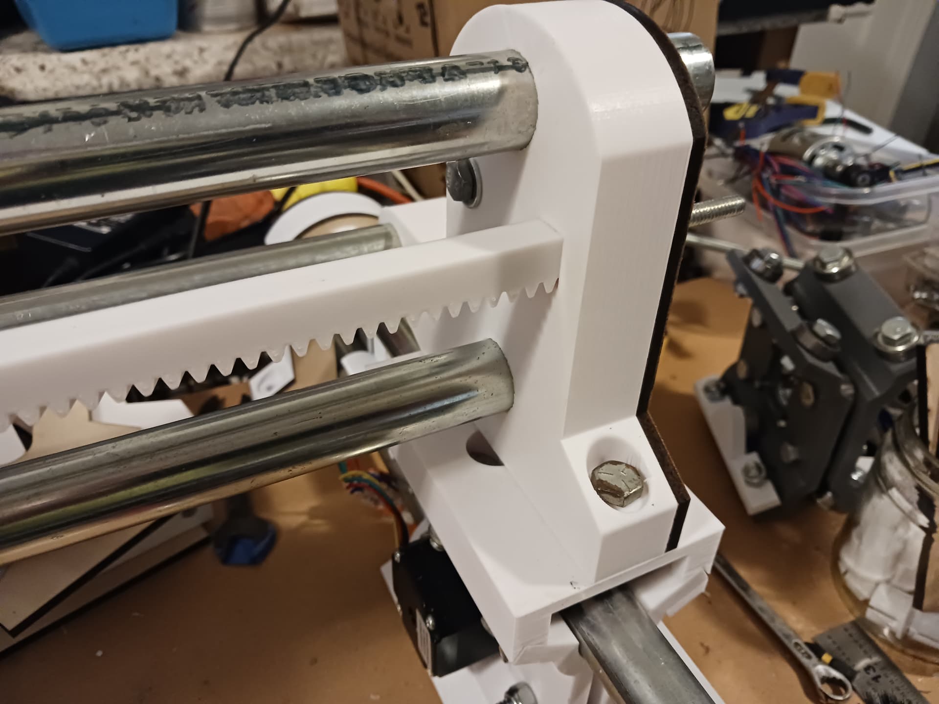
Alright, everything is in place and very snug… but a little fiddling with it should make it all work. It could probably use a bit more adjustment to make the conduit clamps a bit less snug. I mirrored the snap-clamps to form a full surround rather than giving it the full 23.5mm conduit diameter… so it’s a tight fit even before tightening the bolts.
I wiggled it around a bit to see what slop was there… not so much slop but a fair bit of flex. I doubt this machine “as is” will ever be rigid enough to do anything but the very lightest of milling jobs. It’ll be dandy for the little 33mm x 33mm laser module however… so there it is.
![]()
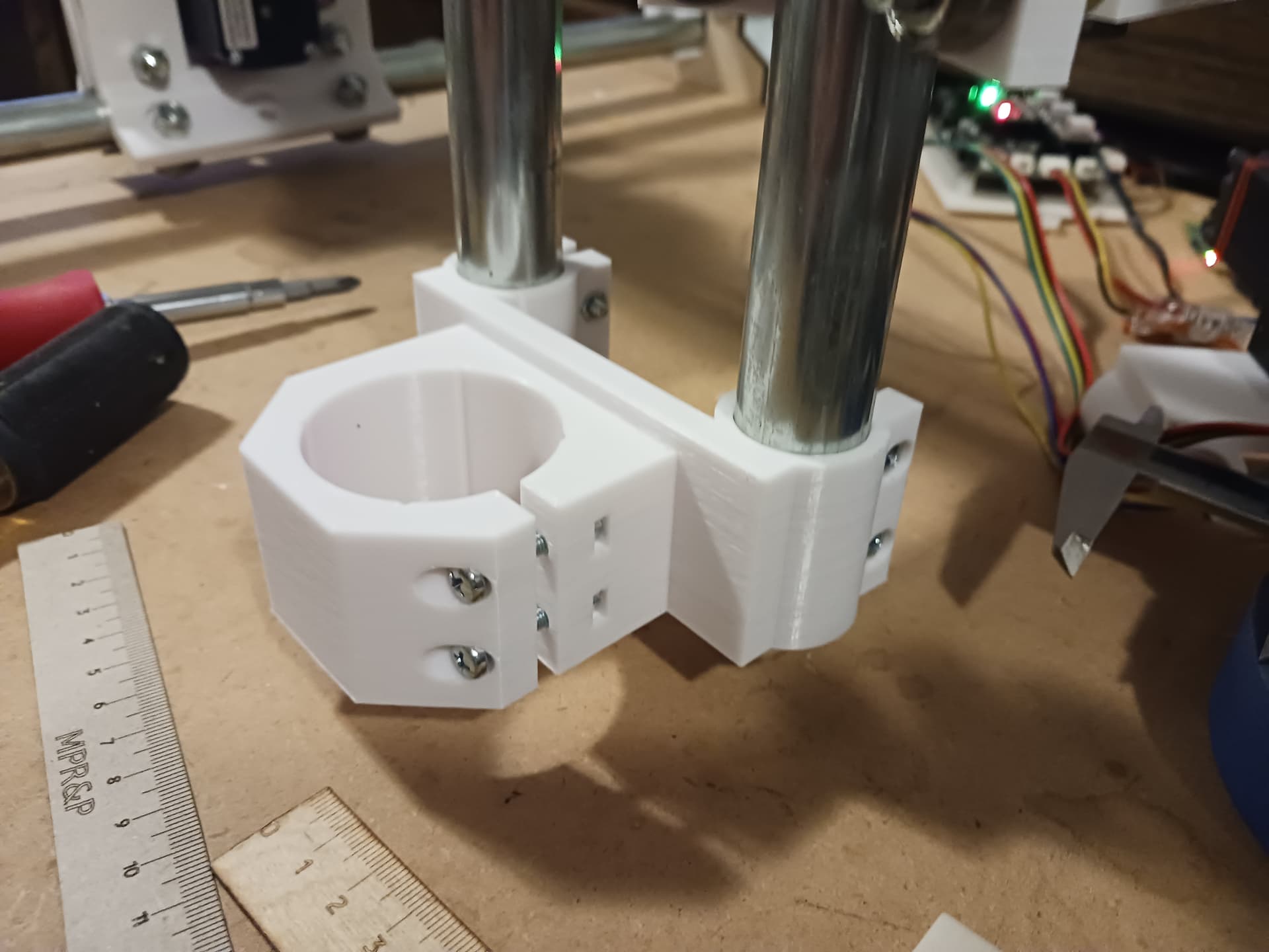
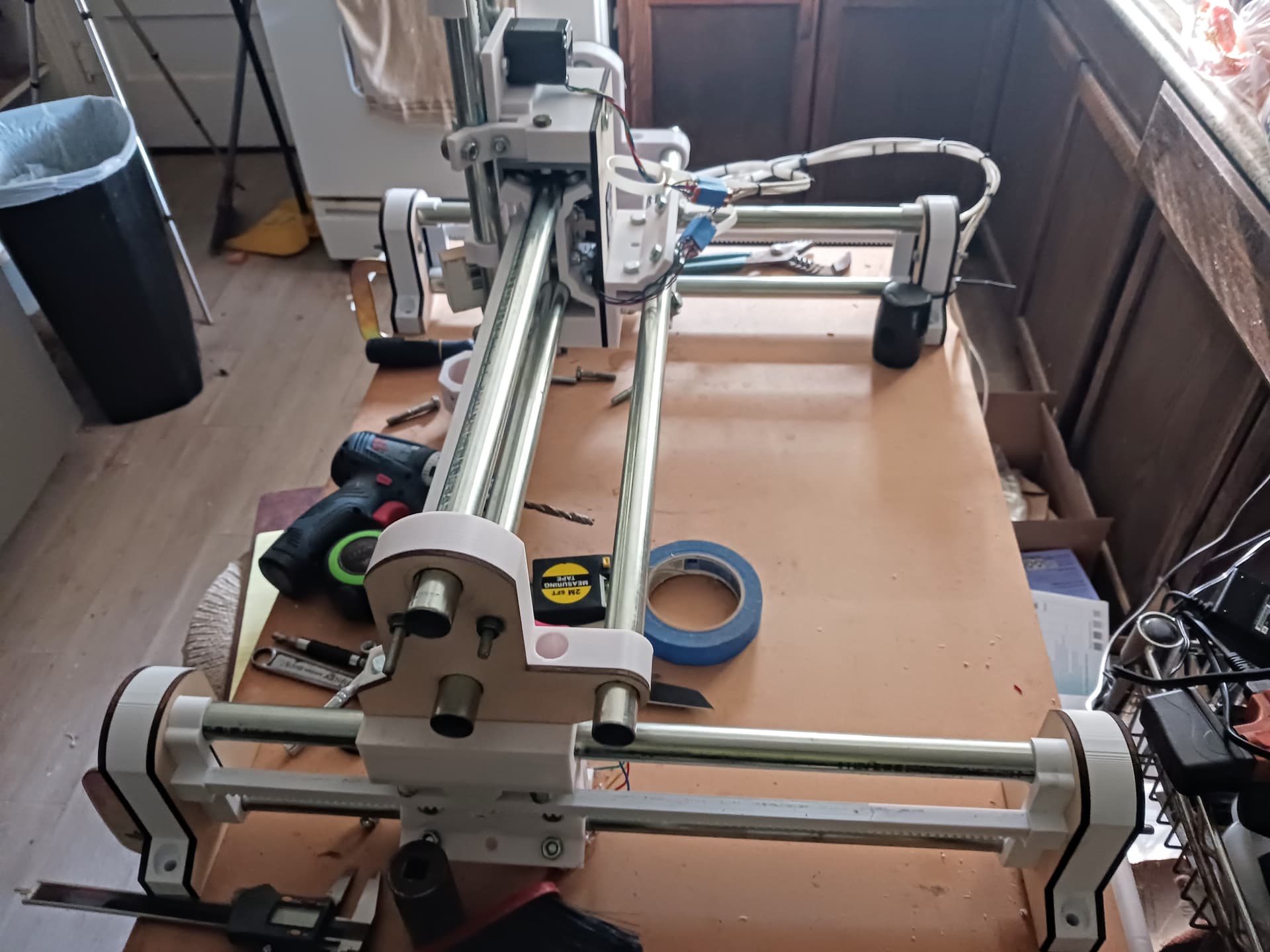
Chasing flex this morning. Last evening I put the 775 motor mount on the Z-rails and found a lot of the flex is in the gantry support pieces atop the two Y-rail assemblies. I think new filler material in the four corners of the gantry supports will help… this is where I see the most movement when I put pressure in the Y direction; i.e. it appears to “rock” on the central support structure.
I also tossed and turned a bit during the night, thinking I also need to add a third rail to the gantry to address flex in the Y direction.
I’m thinking the triangular “truss” formed by the rails would help immensely. A roller assembly could be attached to the Z-backplate to move along with the X-axis and the third rail ends somehow supported by the slotted end support and/or triangular clips. I’m going to mock it up with simple clips first to see if it tends toward the desired effect.
Since I’m working with only one 3d printer, it’s slow going. Hope to get enough pieces printed today to possibly start mocking it up this evening.
Thoughts or ideas?
Left to evolution, things start to resemble a LowRider.
I was flexing my own machine, and triangles are the way you kill the flex. I’ll elaborate a bit more about this later in the evening when I’m not on a lunch break.
I’ll have to defer my discussion till tomorrow, long day today.
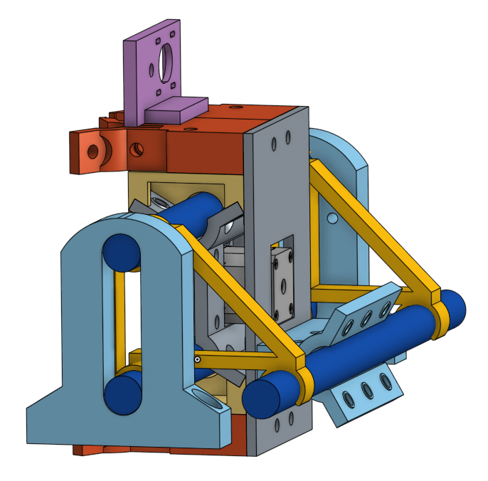
I’ve not yet assembled the rest of the Z axis, but I have done a lot of tugging, twisting and mock motion of the skeleton. For pen, laser, drag knife as-is the design is awesome. Probably even adequate for light routing with a small spindle like the 775.
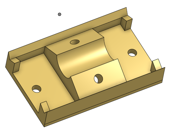
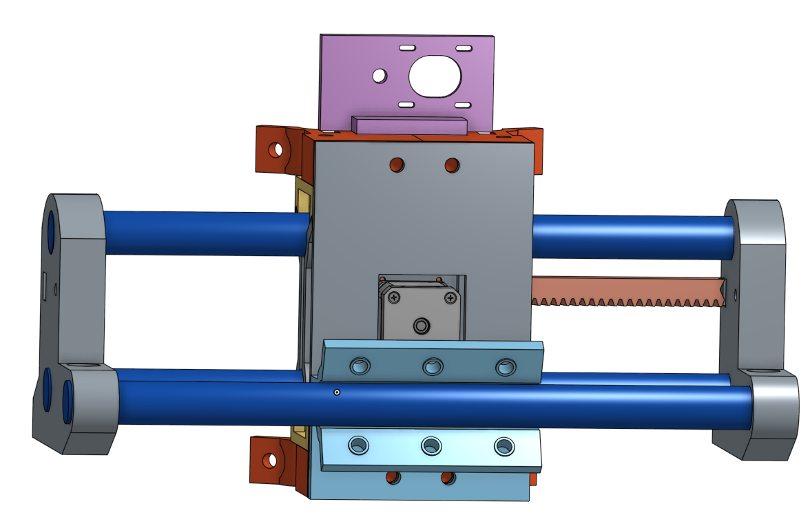
Twist is the challenge, but I’ve also seen some motion that I’m curious about simple design refinements might address. The carriage ends have an oval racetrack the two tubes share, with the tubes retained by a combination of the clip and the carriage ends.
If the carriage end was instead made the same thickness of the cage and clip, with the tubes going through individual holes, that’s an interesting exploration. In fact, you could put the cutout for the rack into that thicker piece, and the through holes for the 1/4-20 threaded rod. Two pairs of each type of hole/recess, mirrored L/R so the part continues to be universal.
Next up, what I call the X axis (short axis) can rock +Y / -Y and could benefit from some kind of triangulation to help resist that (as you note above so clearly). It can also rock at the base of the tool +/- X because the two carriage ends are mounted with two bolts that are in line with the Y rails. Changing the configuration of the monting such that there are 4 mounting holes in an H pattern would still be strong in the +/- Y axis but may add considerably to resisting +/- X rocking.
Heck, just making the carriage ends the same width as the top of the carriage would probably help a ton even with just the 2 existing bolts.
Also, boxing the carriage part with the nubs or other structure that you point out above might be a major improvement.
I noodled a bit more about what a machine might look like with at least 2 sides that are the “triangulated tube configuration”, one for the X axis, and one more for whichever of the Y rails makes sense for the machine. In that respect, low-rider esque (one rail with extra rigidity, one rail needing less because the triangulated rail takes all the flex up)
A few other minor observations: The clips for me are just a bit too tight for the rack. I can trim the clips to bevel their entrance just a bit, and hand chamfer the end of the rack that goes into the clip, then force them in. That tells me that tolerance should be a bit looser on the clip, maybe .1 or .2 mm in both axis of the recess. It potentially adds a bit of slop in the rack when not tightened, but with the 1/4-20 rod tightened up and in tension, that rack is very solid.
I have a few ideas about adding some cable routing/management stuff, but am still working that through. The tubes can really help as places for routing.
Overall, I’m super happy with my build of the 2nd iteration of this machine, and I’m going to keep at it and likely finish this build up and get it running- regardless of any iteration.
This for me has completely validated the question of “can you build a mostly printed rack and pinion in the V1 MPCNC style”? Heck, yes, you can- and I see tremendous potential for evolution of this concept.
I’m having a blast thinking about and assembling this design. Thank you so much for sharing.
I’ll get some more pictures of my parts and assembly as the week goes on. It’s a pretty busy week for me, so again likely slow.
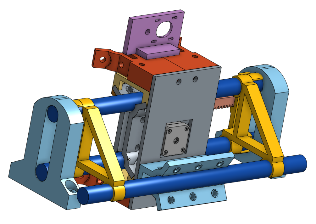
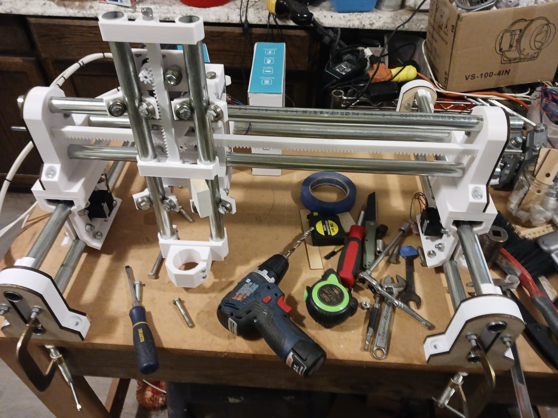
I know we’ve been working toward the idea of an integrated end support that incorporates all the currently layered features provided by “clips”. And now that we’re moving to a “triangulated tube configuration” (I like that terminology…) on at least one axis, the gantry, I’ve started mocking it up in Onshape.
Current “layered features” approach. I feel/know this is incomplete as shown and the conduit end need to be captured by the end supports somehow…
An “integrated features” end support…
Obviously we get a cleaner look and more range for the same footprint – and solidly “fixing” everything in place seems it would be good for rigidity purposes – but I feel I may be missing something. I’ve never built an LR4 or studied it in detail but we seem now to be going – structurally – down a more familiar path (to you and those who have designed and/or built one). Are these “integrated ends” I show above enough to provide the “rigidity” the LR4 has, and we’re now chasing?
I know that pulling everything firmly together with the 1/4" threaded “rack rod” gives a the entire assembly a nice, solid feel… do we need a threaded rod through one or more of the conduits as well? It’d be pretty simple to add a threaded rod through the newly added third conduit (and maybe the bottom one?) and provide a bit more rigidity? I know we want to run wiring through one or both of the others…
I guess I just need to print these integrated end supports and “see what I can see”… and maybe put another roll or two of filament on order.
Later.
I’ve printed the Jeeping Johnny CSM with a bunch of upgrades by Pandel as well. Lots of fun to play with.
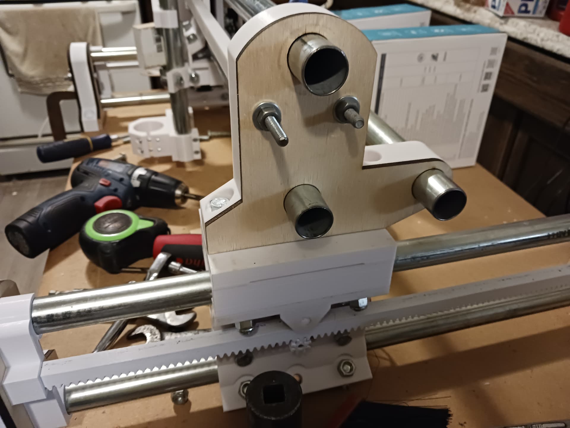
I swapped out all the layered feature parts for the integrated end support and the gantry is greatly improved… much more rigid. There is also now room for another ~2" (10 teeth or so) of rack with the same length conduit and threaded rod. I still have a little flex in the connection between the gantry ends and the Y-axis rail assemblies… but I really need to address the wire management so will live with it for now.
I suspect that the Y-assemblies probably should be turned “motor out” to accommodate the wiring and cable-chain would probably be the way to go. But I suck at wire management so am anxious to see what other folks come up with.
I’m not going to put the integrated gantry ends out on Printables until I hear some more thoughts on what can and should be done to further improve the rigidity. I’ll be happy to share the parts I’ve got here on the forum if anyone is interested in playing with them. I intentionally made everything a pretty tight fit to keep slop to a minimum so assembly of the integrated gantry is a bit more tedious than before. But the machine that is out on Printables now is good enough for pen and laser so I’ll let it ride for now.
– David
DM me the parts and I’ll start printing a set to test with.
These look like a major improvement.
I’m quite looking forward to having some time to work on this again over the weekend.
Are the threaded rods the only things rigidly connected to the gantry end supports in the X direction? It feels, to me from the pictures, like having the conduit (particularly the topmost conduit) clamped in place with something like an M6 or M8 screw would help with rigidity… but could cause over constraint issues if the y rails aren’t parallel.
Hey, Daryl! Welcome to the party!
As this machine is still a work-in-progress, nothing is cast in stone, of course. At this time the 1/4" threaded rod is the only thing drawing the ends together. However, things are intentionally fit so tightly at this point – to avoid slop – that it feels sufficient… especially for light loads like a laser or pen.
The triangulated tube gantry setup dimensions are set in CAD (Onshape) to just a tenth or two millimeters over the 23.5mm OD of the 3/4" EMT and the spacing between them adjusted to add the third tube. My test parts are so thick and tight a fit that I had to drive them together with a rubber mallet… and with the thickness of the end supports being greater than the diameter of the EMT there’s really not much chance I can mis-align them by hand once they are fully engaged. The end supports are identical and printed on a Prusa MK3S printer from the same gcode so I trust the spacing is the same at both ends.
I think that – should this design ever see duplication and refinement – the fits would need to be relaxed so parts slide together and are then held in place with some sort of clamp scheme or set screws. But with the threaded rod through the rack and multiple conduits in each assembly, I should think there would be ample opportunities to draw the end supports together to sturdy the whole thing up if necessary.
Again, welcome to the party.
– David
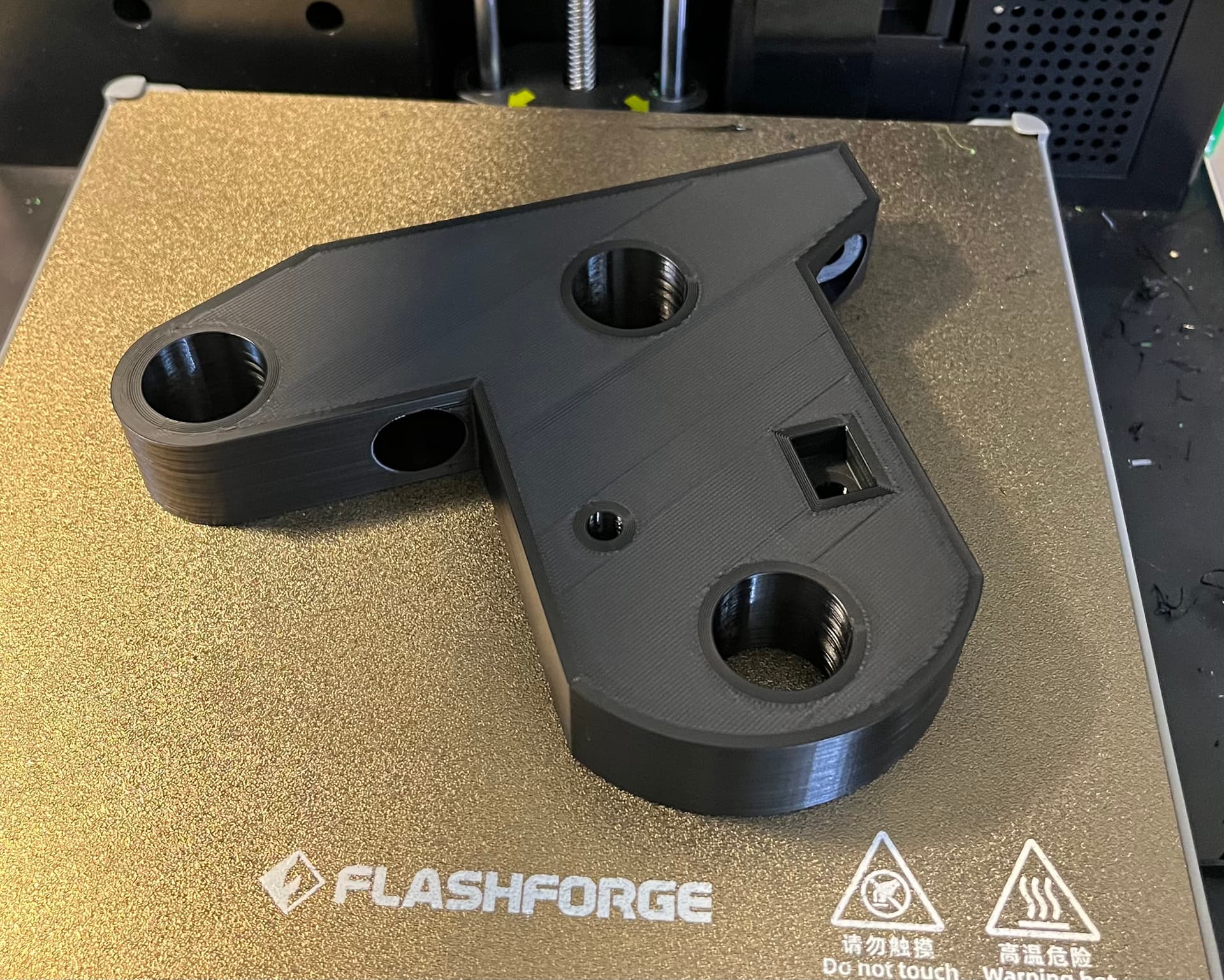
First two big parts are on the printer, next two should start this evening after those finish.
@Code_Pluto have already modified the lr4 Yz plates for longer nema17s
MPR&P range of motion test. Five times around elliptical path 380mm in X and 330mm in Y… approximately 400mm x 350mm, max. Moving at 6000 mm/min…

Woo hoo!
I have parts coming off the printers.
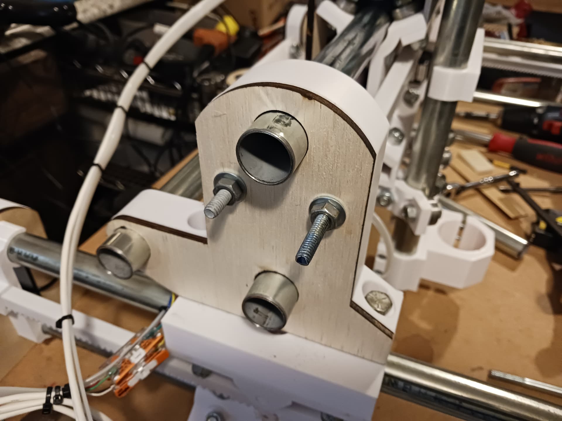
I realized that my back plate can no longer be freeform, I’m going to redesign it- but how thick is your cad for that (you laser cut yours).
back bearing to eventually team with my new back plate
I allowed for 6mm thick backplate in the CAD but the ply I laser-cut actually measures a tad under 5mm thick. I recognized at the time that the backplate thickness might vary a bit and thought that if I keep the CAD at 6mm I can always shim it with cereal box cardboard or printed shims. It turns out that there’s apparently enough “give” in the components involved that mine just snugged up nicely without binding or creating a bunch of drag.
Your parts are looking good… hope to see something moving soon!
![]()
Parts came off the printer. Still working on a backplate design.
Didn’t make much progress, I spent the weekend helping a family member who had their car stolen.