I use a stack of shim washers just slightly bigger than the screw head. Once I know where I want the trigger point, I stack washers to fill the space and finish squaring in software.
Sanding them a bit may improve it even more. I’ve popped a couple early on but since I added the washers I haven’t found myself worrying about it anymore.
Well, I measured using the most precise effort to date, to check both accuracy of travel distances (commanded versus actual traveled) and my diagonals compared to check square, and it was not out as badly as I thought it would be. However, I did make several adjustments and re-ran tests and measurements several times, and my full-size LR4 machine is now very accurately calibrated:
Short-Axis Straight Travel distance: Now spot-on. Programmed target travel of 1140 mm, with actual travel of exactly 1140 mm on both ends of the table.
Long-Axis Straight Travel (Average): Programmed target travel was 2355 mm. The actual travel was slightly different between the near side and the far side, but just barely. Average is \frac{2355.2 + 2355.0}{2} = 2355.1 mm — 0.1 beyond what was commanded, which is \mathbf{0.004\%} error. This is excellent.
Squaring (Diagonals):2625.3 mm vs. 2625.0 mm, a difference of \mathbf{0.3} mm over 2.6 meters. This means my gantry is squared to better than 0.012\%—a fantastic result for a belt-driven DIY machine.
I’m very happy with this.
In fact I made one more tiny tweak to the pulloff that I think will make the diagonals match even more closely.
I haven’t actually done this to test it, but I’ve had the same issues everyone else has. The (to me) obvious fix, move the endstops from the gantry onto the belt holder itself. Redesign the min holders with a slide off cover housing the endstop with the blade poking out, centered so it contacts the big flat section of the gantry. No more flexing, far fewer failures.
That would mean Y2 min would have a 12’ set of wires, and having to wire manage them next to a belt that goes down to zero length, and across the X axis it would be opposite the other set of wires. Wire management nightmare.
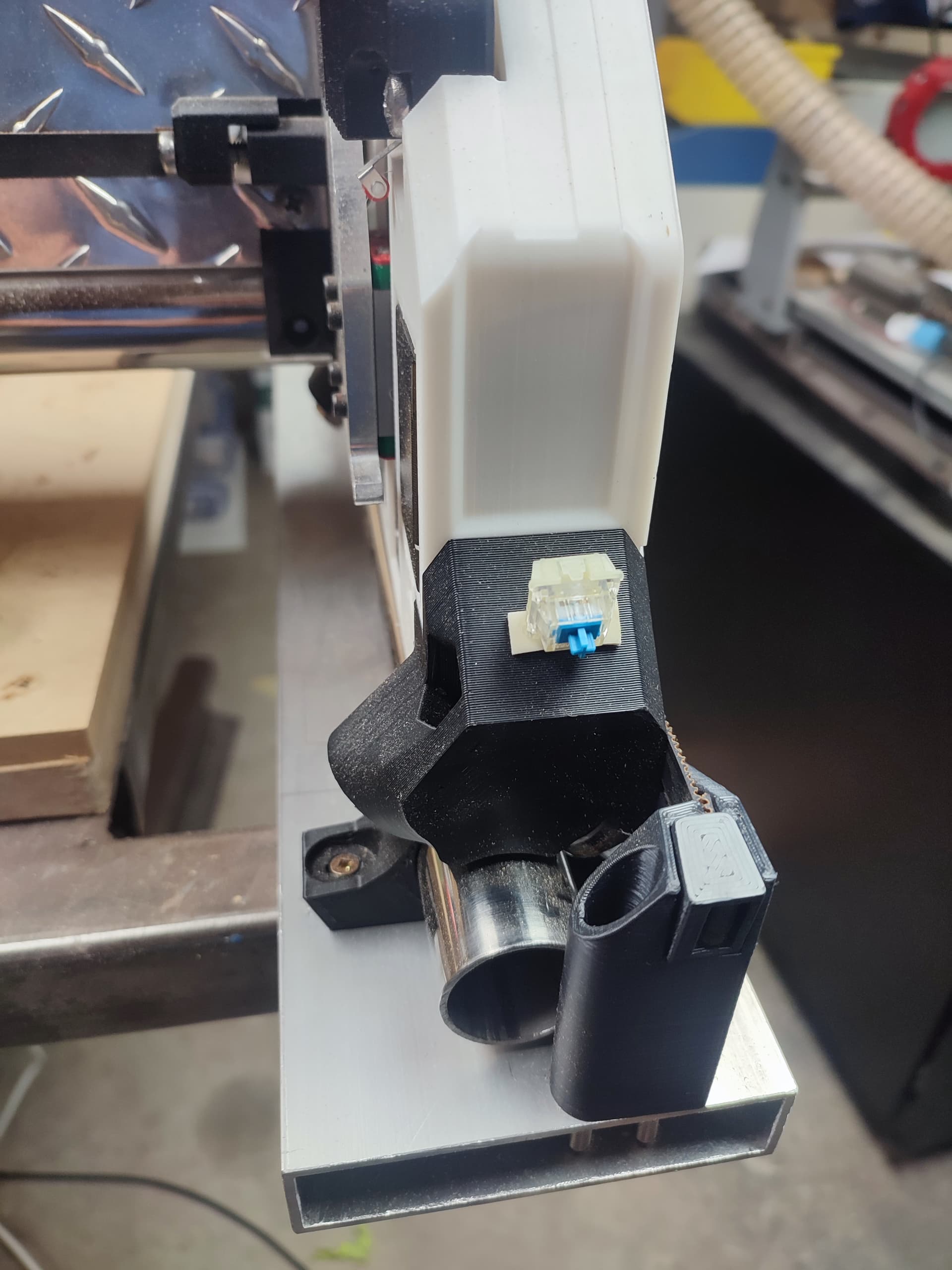
P.S. absolutely great project. aluminum checker plate gantry struts cut on the machine itself with plastic temporary struts. the cut was a lot of passes but surprisingly easy
As mentioned in other posts, I use Hall switches, which are COMPLETELY trouble-free. These go low when a magnet’s South pole comes near. No debounce needed, no levers to break off or catch on things. Repeatability i measured: 15 microns. I pull them up to 5V with 1k, and add a 100nF cap as recommended. They are less than a dollar each. AH3391Q-P-B HALL EFFECT SWITCH, UNIPOLAR, SIP-3, 60 cents each at Farnell.
If you really love micro switches for some reason, just remove the lever and have the screw push the little red button directly. They put that lever on there for things moving or rolling _past_ the switch to trigger them. That is not our situation with endstops.
And, indeed, on my LR4, I occasionally have an issue where the angle of the machine prevents the end-stop switch from triggering, and the machine drives right straight past the end stop, and I would really love a more face to face, direct approach that does not permit that type of mishap.
I really liked this suggestion. With them being able to run at 5v and using an open drain they’re really easy to use in place of the mechanical switches. I’ve looked at adding inductive sensors but with their higher voltage requirements and the way their signaling works (at least the ones I bought) they would require extra components and got more complicated than they were worth pretty quickly.
Anyway I drew up some mounts for SIP-3 hall effect sensors for the y axis, I expect they’d need a 5 minute tweak to use on Z or X. Here’s the onshape document for anyone interested. It’s also a decent example document of making an assembly with existing components then making a part studio in context of the assembly. hall effect sensor mount
Way to go, David! Much nicer than my “blob of glue” approach.
I don’t understand why anyone still uses mechanical switches. They break and wear out, get dust or water in them, need debouncing code, and can too easily be triggered by accident. Hall switches are what the auto industry uses. In case you didn’t watch it yet, here is the part of my MPCNC video about Hall switches. I note that these are not to be confused with Hall sensors, which are analog.
I’m very interested in these mods. I love my lr4 but these little switches drive me crazy. I use my lr4 table as a general assembly table as well and I can unclip the belts and move them out of the way but the screw for the switches stays put and are so easy to bump out of alignment. I’ve broken so many of the little switches from getting caught on the screws wrong (ordered a big bag of extras lol). They are easy to swap but I’d love to just move over to a more reliable setup.
My hall effect sensor switches have arrived, and I’m looking to get them implemented. Couple quick questions:
I’m gathering the “sensitive business end” of the sensors is on their “flat side” as opposed to the “tiny tip”… Is that correct? It seems you have the opening sized to “reveal” the flat, large face on the side.
For wiring them up,
do I connect to the two outside leads/wires, isolating the center lead/wire?
does it matter which lead/wire gets attached to what? Or do I have to be careful, treating the thing like a “one way only” type device?
Sorry for so many questions. I tried to download some type of wiring schematic or specifications diagram from digikey, but did not find it.
For info sake, this is the exact listing I bought from:
I kept searching until I found what claims to be a datasheet for it, which is available here:
one other question:
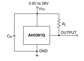
Looking at the schematic, it seems one of the outside leads is for the “voltage,” i.e. power input, while the other outside lead is the “output” i.e. signal — but this raises another question: is that based on having the flat side with lettering on it facing up or down? Sorry to be so naive on this thing.
The place where the switch has numbers etched on it is the sensitive part. You ought to move this discussion over to Tom’s all about Hall switch endstops. There I posted the datasheet.
BlockquoteI’m gathering the “sensitive business end” of the sensors is on their “flat side” as opposed to the “tiny tip”… Is that correct? It seems you have the opening sized to “reveal” the flat, large face on the side.
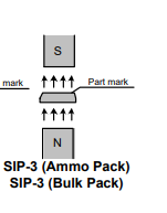
Here’s an image from the datasheet. You can picture poking the 3 prongs into the ground and looking down at the part. The taper points to where the sensor is. So you want the taper pointing to the south side of your magnet.
Blockquote 1. does it matter which lead/wire gets attached to what? Or do I have to be careful, treating the thing like a “one way only” type device?
Yes you can think of it as a one way device. Output and ground cannot be swapped. The device needs the relationship between vdd and gnd established for the switch to work properly and allow output to be pulled down.