A major goal for this build is to experiment with saving time in two ways:
Portable outdoor unit to run unattended in a safe location
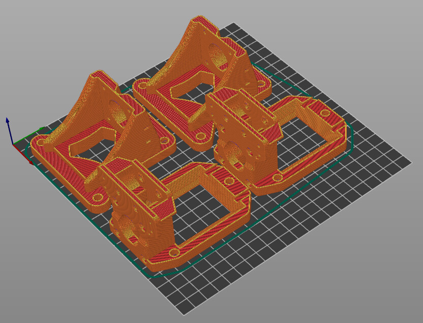
Dual X-carriage for “IDEX” style machine
A low chance of fire is still much too high to run unattended in the garage, but with a long extension cord I can run the machine in the middle of the yard, and the risk of fire puts only the machine at risk, not the house or its residents.
The machine won’t stay outside most of the time. I’ll have to remove the X axis from the table and bring it inside whenever I’m done, and it appears that should be really quick.
With two X carriages, tool changing is simple and reliable. Two tools is a huge step up from one, and there is much less marginal utility in a third tool, at least for what I usually want to do. I am pretty confident I can get existing “idex” (independent dual extruder) firmware to handle the tool change without a lot of extra work.
I’m keeping my double-decker Burly in operation but I’ve taken apart my smallish Primo to reuse the motors, pulleys, bearings, etc.
Dual X will need at least 6 drivers and I’m thinking of the SKR Octopus or similar, for an eventual rotary axis or two.
I’ll post more about the table as it gets more developed.
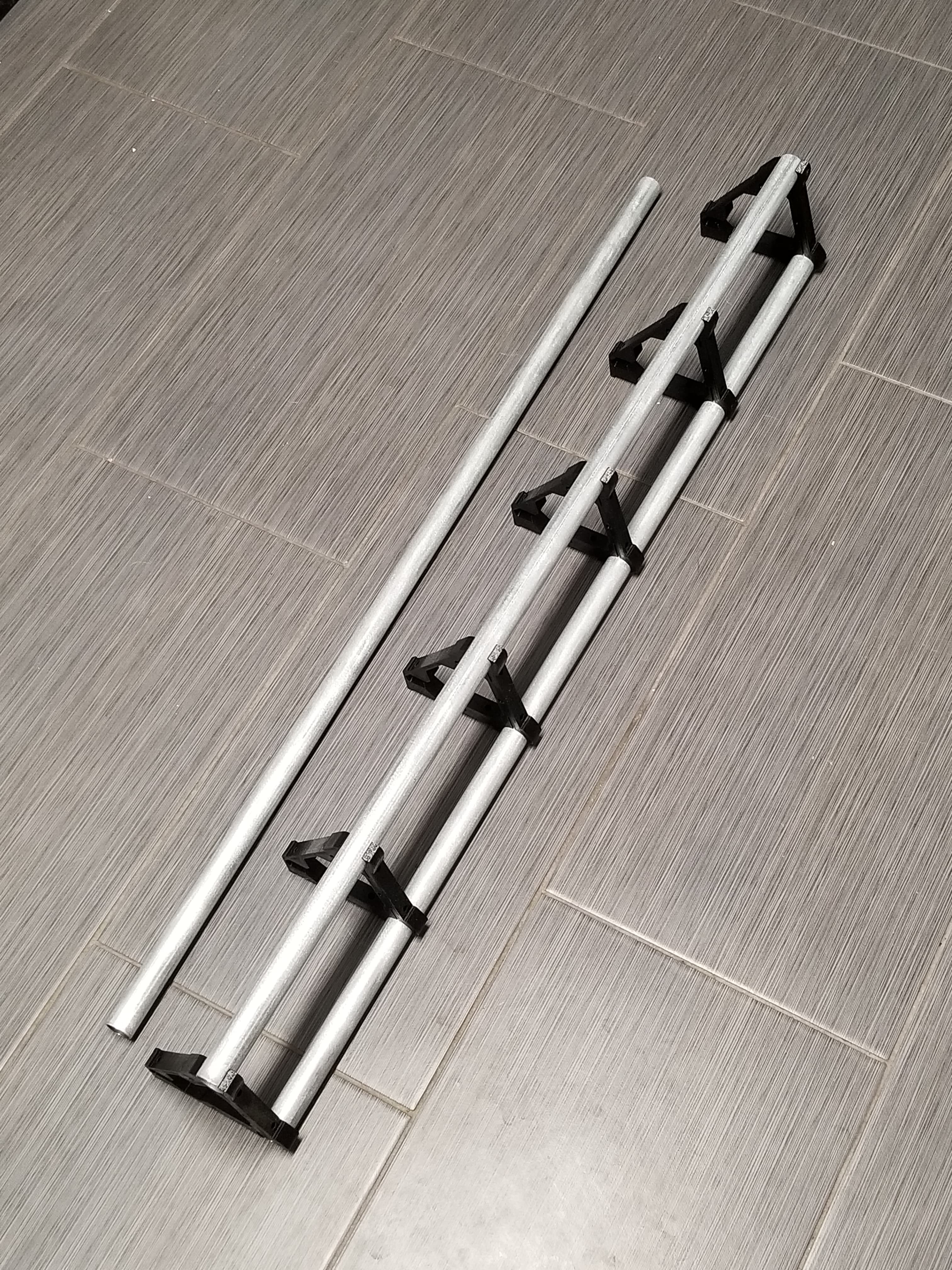
A workpiece size of 24x48 inches is the largest I’m likely to use. The dual X carriage eats up some space on the X axis, and I’m looking at 975 mm rails so each tool can do 24x48 inches, and the ovelapping area for dual-tools is a bit less than 24" but that should be okay.
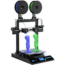
Independent dual extrusion in the world of printers has two print heads on a single X axis rail. They are constrained to the same Y and Z, but are driven along the X axis independently.
Lowrider should be able to do this too with two routers.
Yes! I had a long chat with him. He was excited about a toolchanger as an interesting challenge but lost all interest once I pointed out that dual carriages could be much simpler and easier.
I felt a bit bad for killing his project, but he was satisfied that a dual-carriage approach was a better way to go in the end.
2 Cores on a mostly stock LR3, maybe switching to 2 or 1 start leadscrew? You ‘park’ the Core not being used to the side so as to not hit stock? Both Cores share the same gantry and belt even, they just have their own X Stepper and limit endstops (both wired in series to same limit switch port, or using separate limit switch port?).
With the right surfacing g-code generator , and enough power, you could surface double speed with both cores? Would you go so far as to have reversible rotation router/spindle, with reversed bit for one Core. So 2 active counter rotating spindles negate, or at least reduce overall rotating force on the y-axis? Maybe counter spinning spindles wouldn’t gain much given other lateral forces. Double speed surfacing could be nice though.
Your neat IDEX idea sounds like a fun mod, look forward to seeing your updates.
On an IDEX printer, the Z offset is zero, or configured at some point (firmware or gcode). Your Z offset between the bits is going to change on every tool change. That is one thing I would look out for. Our weird G38.2 probing won’t work to set the offset between the two tools. Hopefully the weight won’t affect the Z calibration.
I’m guessing the difference between where the two cores can reach is probably the width of one core, which is pretty significant. My guess is you will need to build something with about 36x48 work area to be able to keep an overlapped 24x36.
Sounds like fun. What are the two most common tools? A straight cut and a V bit?
Oh man, I think this could be a winner. Making the YZ plates, I switch between 1/16" and 1/8" several times a day. I think the average user could benefit from milling and a chamfering bit, or big mill little mill, or for carves a flat and vbit.
You can skip the Z offset initially but a basic tool setting. Move each head to the same position and set the tool on the surface and tighten it down. That should be pretty easy to get very close. If you are not swapping mid cut that should be fine.
So I wonder if I could make a smaller Core. This could really be worth exploring and really up production and part quality. Dang Jamie, let me know what I can do to help.
Would it be possible for “Compact Core” (holding camera/laser/other low torque parts) to be mounted/unmounted relatively quickly without having to partially disassemble the gantry? With X belt holder being quick releasable like the Y-Axis?
There is a lot of room inside the gantry too (not enough for a nema23). Maybe that is where the X axis should go? But then, you would need two belt paths for an idex.
Not necessarily. Having 2 carriages on the same belt should work, with independent X motors, since they don’t affect the distance from the respective sides. It will put more load on the belt, if that’s an issue, but it should ve manageable.
You would need 2 belt paths with a loop belt, like an I3 X axis, but with the motor moving with the carriage, it shouldn’t be a problem. In the spirit of having the least amount of redesign, I would advise this route, even if beefier Nema 23 motors are desired.
This doesnt work as well, because the length of the belt changes with an extra drive motor. As soon as you remove that drive from the belt, the overall length of the belt changes, and a quick disconnect is no longer feasable… unless you do dual belt paths.
The way I’m estimating it, a single X core has a working space 180 mm narrower than the rail length.
Then two X cores with one just sitting there (taking up space) means the other one has a working space 360 mm narrower than the rail length. And since the reachable working space of X1 is offset from the reachable working space of X2 by 180 mm, so the overlapped region is 540 mm narrower than the rail length.
I’m targeting a size where each one can access 24" width and the overlap is about 17", which is already big enough for everything I anticipate doing, but I want the option of doing full 24" with only one tool (without having to remove the other core). This makes the rails 975 mm (about 38") by my calculation, and with a single X this would mean about 31" of working space. So you lose about 14" going to dual-carriage.
Setting the tool lengths physically is fine, and probably preferable, but I think it’s also possible to use workspace offsets G54 etc for the two tools. A G92 command resets the zero point within the current workspace, so you can retain the Z offsets for two tools. You would want to pay attention to clearance heights to not crash when switching tools.
To optimize for compactness, I’m sure there are a lot of things that are possible. An “L” shaped core and an inverted-L shape could retain the width for stiffness while allowing them to nest nicely. Mounting the motors remotely with belt loops is certainly possible.
Sure, losing some working space is not nothing, but it’s not that big a penalty and some is unavoidable anyway because the routers will collide at some point. Maybe squeezing some width out of the core will be worth it, but maybe not.
That is a well thought out plan, IMO. I agree that making dramatic changes aren’t necessary. If everything goes south, you can always take one off and have a decent sized LR3.
After three years, this is the first time I’ve used the back right corner of my double-decker machine. The working space is about 36" x 24" and my strut plates are a bit more than 38", which fits comfortably at an angle with a couple inches of margin.
Trying to keep this in mind to not oversize “just in case”, if anything dual-tool 17" working space and single-tool 24" width could be more than I need. I could probably get away with dual-tool 12" and single-tool 19" (or single-tool 26" with the second core removed). But the difference is small enough I am okay with it.
These strut plates are a little bit thin and floppy but the stiffness in the plane is what matters. I can replace them easily enough if I suspect they are deflecting.
I’m very tempted with the Z axis height because there is not much penalty to having larger unused Z capacity, but I am going to try to stick to the 150mm Z rail length.