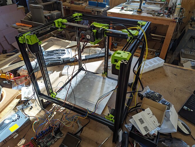
Looking good! And that green is something else. Really pops!
I set up a jig to sand the ends “perfectly square”. I do have a 2x72 belt grinder that made that possible but you could do it with a disc sander pretty easily. I spent a lot of time measuring and sanding until everything was perfect.
Does that mean it is perfectly square? Nope! But it looks good!
ABL doesn’t work if you Z height is taller than your firmware is set to ![]()
Stopped here for the night. Something isn’t right in my firmware.
The first point for ABL worked, but the second point moved so that the bltouch was off the front of the build plate, so it fails.
Figured it out. Some dumb ass wasn’t thinking about what he was doing and didn’t realize his X and Y axis were swapped.
Doh!
ABL is running now
I was trying to figure out how that could possibly happen… ![]()
Well. Now I really am done for the night. I need to print more Z belt ends.
I was working on the bed levelling stuff and one of my Z belts came loose. I went to loosen the belt end and the little M3 bolt stripped. So I tried to drill the head off and broke the 3d printed part.
I’ll work on this more tomorrow, maybe.
Leave it to me to discover new ways of breaking things ![]()
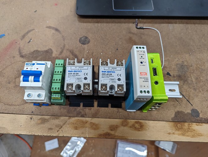
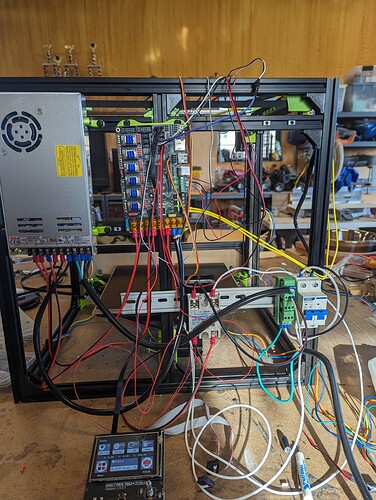
One last picture for the night.
From left to right,
AC circuit breaker
AC distribution
Bed heater ssr
Enclosure heater ssr
5v PS
Raspberry pi
The raspberry pi will control the chamber heater and an exhaust fan for when I have the enclosure done.
I bought 24v fans for the enclosure so I can run them straight off the 24v PS.
I’ll add some more extrusion across the back for this, the skr, and the 24v PS.
I’ll make some type of small enclosure for the electronics and put a cooling fan on it.
I had purchased all of this for the big cnc router I have yet to design ![]()
Today’s progress.
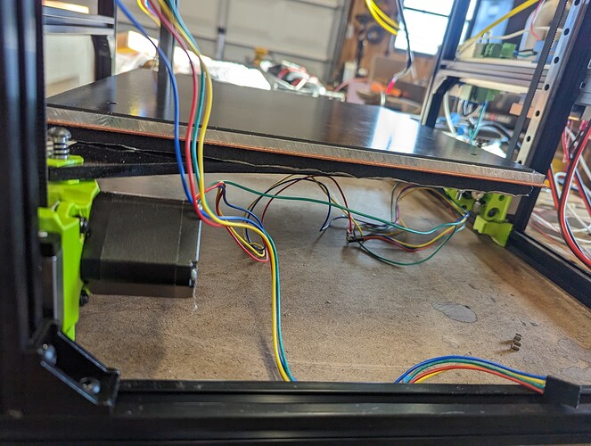
Heated bed installed. This thing heats up insanely fast. I think I need to enable pid control of it. The aluminum plate is a huge heat sink and you can see the temperature cycle pretty wildly for a bit before it heat soaks.
The 12"x12" aluminum plate measured in at 307mm x 307mm, so the heated bed being 310mm wasn’t too bad.
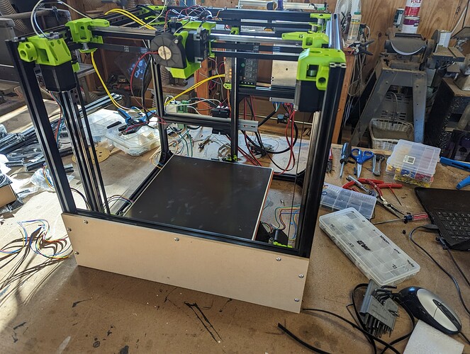
Front panel installed. I think I’m just going to go with MDF. I’ll paint it white.
And I started wiring electronics. I have the heated bed and extruder working. I need to length the wires for the parts fan, some of the steppers, and one of the end stops.
It’s been forever since I’ve set up a new printer, so I had to redo fans and temp probes a few times to get things correct.
I had to order some more hardware.
The M5x8 bolts aren’t quite long enough to go through 1/4" mdf and reach the T-nuts. I only had enough M5x12 to do the front panel for testing.
I also needed to order some more appropriate wire for extending fans and end stops. I have plenty of wire for extending the stepper motors.
Thanks to the magic of Amazon, I should have all of that by Wednesday, so I should get to work on this some more on Thursday.
At some point I have to rip everything back off of the back of the machine in order to install the back panel. That should be fun. The bottom and side panels should be a little easier to install. My plan is to put the T-nuts in place and use a dab of hot glue to hold them where they need to be for the bolts to hit them through the panels.
Something I learned this morning…
Polarity matters on the BL touch black and white wire. After moving the electronics to the back panel of the machine, the BL touch stopped working. I went back and looked at the picture from the first time I wired it up and saw the difference. I guess I just got lucky the first time around.
One thing I’m still not sure of is which Z axis goes with which motor. Z0, Z1, Z2, goes with which ‘left, back, right’ .
I saw this posted in a thread somewhere but was dumb and didn’t bookmark it. Now I’m questioning things.
Right now I have it wired as
Z0 → left
Z1 → back
Z2 → right
Sorry I have it in my notes, I thought I already added it to the page.
*Stepper location
Z1 to Z port
Z2 to E1 port
Z3 to E2 port
|  3  |
|     |
|1   2|
Thank-you!
I’m missing something.
How do you get the G34 command to level all 3 Z axis before doing the mesh level?
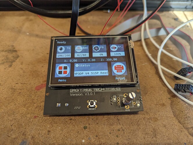
On a positive note, my enclosure temperature probe works and shows up on the temperature graph with the rest of the temps.
Run G28, then G34, then G29. That should do it as long as you do not move or power down in between.
If you put them in order in your gcode it does it right.
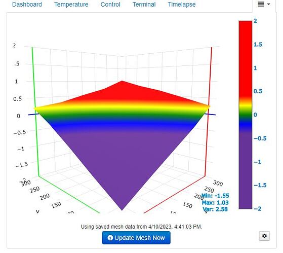
My G34 isn’t doing something right.
The G34 is only testing the center point on the bed.
Here’s my M422, so not sure what’s going on
Send: M422
Recv: M422 S1 X5.0000 Y5.0000
Recv: M422 S2 X295.0000 Y5.0000
Recv: M422 S3 X150.0000 Y264.0000
Recv: ok
That is odd. Are you using the release or the nightly? The nightly is actually broken in terms of the probe. I have been following that for a while now.
It should be the release. I did have to rebuild for my larger printer size.
