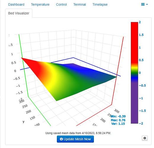
Is the G34 command supposed to be more than just G34 ???
I use this, But I know it also works without the Z move.
G28
G1 Z10 F6000
G34
G29
So G28 and G29 work for you, just not G34?
Correct. G34 only probes one point in the middle of the bed and then stops.
I’m very new to mesh leveling (any auto-leveling, really), Is there something I failed to setup?
I figured it out.
At some point while I was having the ‘other’ XY issues, it looks like I had changed the bed edge value to 15. So the printer couldn’t move to the G34 spots
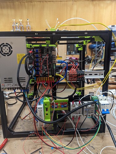
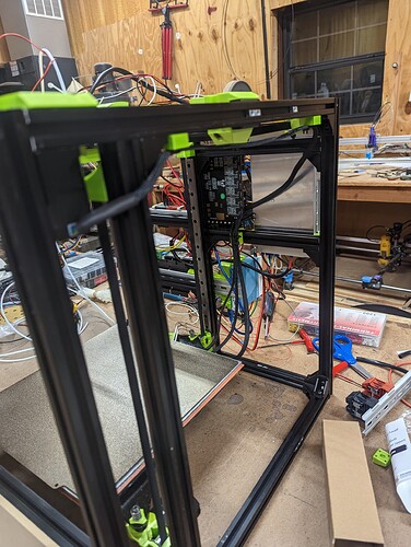
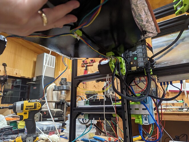
Better. This will do until I’m finished with the cable management. I think I have wires being pulled.
I’m mostly just happy it’s working.
A few notes for other small changes I made since the initial build. I had to move the Z axis on the left side back just a touch. The Z mount would hit the stepper on that side before reaching the top. I only had to move it a few mm.
I also notice that the xy mount on that side hits the back mount at max Y. Maybe another mm or so. Might be easiest to adjust the max y until it clears.
I also still need to do a final squaring of the machine, so it could be related to something being skewed. The plan is to do that when I install the panels. I’d like to see it print something before I go through that, though.
My son has soccer practice on Thursday and my wife is out of town this week, so my next chance to really work on the printer won’t be until Saturday.
Congrats on getting this far!
That is the second time I’m hearing of things hitting.
When you get a chance shoot some pics. Nothing on mine are even close to each other. closest thing on mine is the left top z belt holder to the left X carrier. 6mm or so and I could adjust a bigger gap if needed.
@niget2002 thanks again for sharing your progress. I appreciate being able to follow in yours and others’ footsteps thanks to the info being shared. Noticed this helpful info from @SupraGuy …
Yeah… that was a bit premature, and before I corrected the lower Z belt holders to go on the bottom horizontal rails. The Z axes have to go right to the bottom. I didn’t see that first.
Heh… You did that too, huh ![]()
I did it also. I mounted the lower z belt mount on the upright instead of the lower horizontal.
@azab2c the part I’m talking about hitting is the left xy carriage with the left idler block at the back. And the left z carriage with the left motor mount.
If my belt was a little longer so that the left stepper mount was pulled farther forward, I don’t think they would hit.
Another thing to look out for is making sure the left/right steppers are turned so that the wires exit out the sides instead of towards the back. I had to turn mine after installing them as the Z carriages were hitting the wires.
@vicious1 I’ll get some pictures later today.
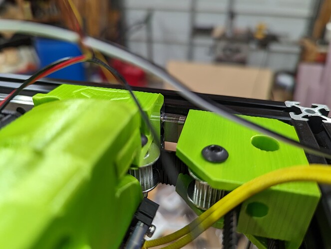
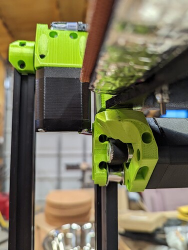
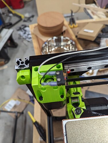
Here’s the pictures I promised.
The xy hitting the idlers was because I still had the metal clips on the bearing rails. The carriage was hitting the clips, not the idler block.
You can just see the clip next to the XY idler block in this picture:
This shows the minimal clearance I have between the left Z axis and the left stepper. This is after I bumped the Z rail towards the back a touch.
From this angle, you can see the size of the gap between the stepper block and the tensioner.
I don’t think any of my issues have been design related. But hopefully they are points you can call out in your documentation.
I tried to track my bolt/nut/brace count while building my machine. This does not include mounting panels or any of the extra stuff I used for mounting electronic gear on the back.
This is what I’ve currently used to build the bare-bones machine.
| M3x8 | M3x10 | M5x8 | M5x30 | M5 lock nuts | M5 slide nuts | M3 slide nuts | extrusion angle | |
|---|---|---|---|---|---|---|---|---|
| Total | 36 | 61 | 35 | 17 | 17 | 35 | 49 | 22 |
I just noticed this does leave off the 4 @ 2.5mm bolts used for the two endstop switches.
And while I’m dumping spreadsheets… Here’s the one where I tracked the parts:
| All prints printed with adaptive tool height, 40% gyroid infill | |||||
|---|---|---|---|---|---|
| 462.46 | 39.5 | 32:05:20 | |||
| Part Name | Quantity | Estimated filament (g) | Estimate Print Time (h) | Actual Print Time | |
| Back Corner Left | 1 | 33.34 | 2.5 | 2:12:43 | |
| Back Corner Right | 1 | 33.34 | 2.5 | 2:00:01 | |
| Bed Washer | 3 | 47.75 | 5.75 | * | 3:16:48 |
| Fan Shroud | 1 | 28.91 | 2.75 | 2:32:20 | |
| Left Stepper | 1 | 28.48 | 2.5 | 1:54:27 | |
| Right Stepper | 1 | 33.84 | 2.5 | 2:08:59 | |
| Tension Block XY | 2 | 8.62 | 1 | 0:48:44 | |
| X Carrier | 1 | 67.11 | 5 | 4:18:37 | |
| XY Left | 1 | 37.32 | 3 | 2:25:46 | |
| XY Right | 1 | 38.57 | 3 | 2:28:55 | |
| Z Belt Holder | 6 | * | |||
| Z Post M | 1 | 35.07 | 3 | 2:40:23 | |
| Z Post | 2 | 70.11 | 6 | 5:17:37 |
And here’s the one where I tracked the extrusion pieces I needed to cut trying to ball park how many 1m sticks I would need.
This ended up being for a 300x300x350 build
| Total | 7 | ||
|---|---|---|---|
| Qty | Length | Description | # of Extrusions |
| Main Chamber | |||
| 4 | 495 | Box Vertical | 2 |
| 4 | 445 | Box Left/Right | 1.8 |
| 3 | 470 | Box Front/Back | 1.5 |
| 3 | 445 | Z Rails | 1.4 |
Okay, That clarifies it perfectly. I would have to check the CAD that is a “tight” zone if the XY belt is tensioned at the max. The tensioning gap on the XY steppers is 5mm max giving an adjustment of 10mm of belt. So if you loosen the belt one or two teeth it will give you a lot more room.
I think the gap should be at least 5 mm with a max of 10. I have one stepper that is close and it is because it is sitting crooked from me tensioning the belts. That also solved my issue with a squeaking belt. Crooked stepper= squeaking belt.
Yeah… no offense, but the whole ‘belt teeth against belt teeth’ wedge thingy was a royal pain for me to get into the extruder carriage. I’m not adjusting the belts ![]()
Having the Z rail bumped back a bit is working well enough for me.
I’ll measure the gap between the stepper and the tensioner in a little bit to see how big mine is.
I use needle nosed pliers and they drop in pretty easy for me. It must be a print thing. I will change those next time around.
I used needle nose pliers too. The belts on the bottom weren’t too bad. The ones on the inside were more difficult. The one on the inside left was most difficult. My printer might print a little tight, but it always measures out accurate.
