I second this ![]() Even using needle nose pliers I was struggling to get the belts in all the way. I still dont think they are pushed in all the way but they are holding so I left it.
Even using needle nose pliers I was struggling to get the belts in all the way. I still dont think they are pushed in all the way but they are holding so I left it.
I think this is a YMMV thing.
Some prints this goes very amoothly, but I found that if you are overextruding at all these are really tight. Also if your extrusion width is greater than your nozzle size it can be very tight even with no overextrusion.
I did a print the other day thst needed sandpaper just to get a belt through the opening.
At least you know that once you get that lock piece in, it isn’t going to let go.
My old printer still prints a small elephant’s foot. The Z belt mounts had to be filed inside the slots for me to get the belts through.
If those parts had a small chamfer on where the belts go into the flat part of the print, it would help mitigate the effects of the elephant’s foot. I almost made the change and then reprinted all of them, but the file worked well.
I put a chamfer on most all parts that touch the bed, but it is fairly small. One or two layers.
I will definitely take a look at the parts if I make any edits to see if I can quickly and easily make it better. If I go too deep I end up with a full redesign.
1 Like
Most modern slicers have some kind of elephant’s foot compensation as well.
Out of curiosity, which side of the Z belt brackets are supposed to be touching the bed when printed? Maybe I’m printing mine in the wrong orientation. I pulled the parts from F360.
True. I haven’t poked around in S3D lately to see if that’s in there and I’ve missed it. I know I can change the amount to print on first layer, but it’s been a while since I’ve played with that.
Wednesdays are my meetings day at work. I won’t be home tonight to work on the printer, so I brought some sub-assemblies to my desk to work on during my meetings.
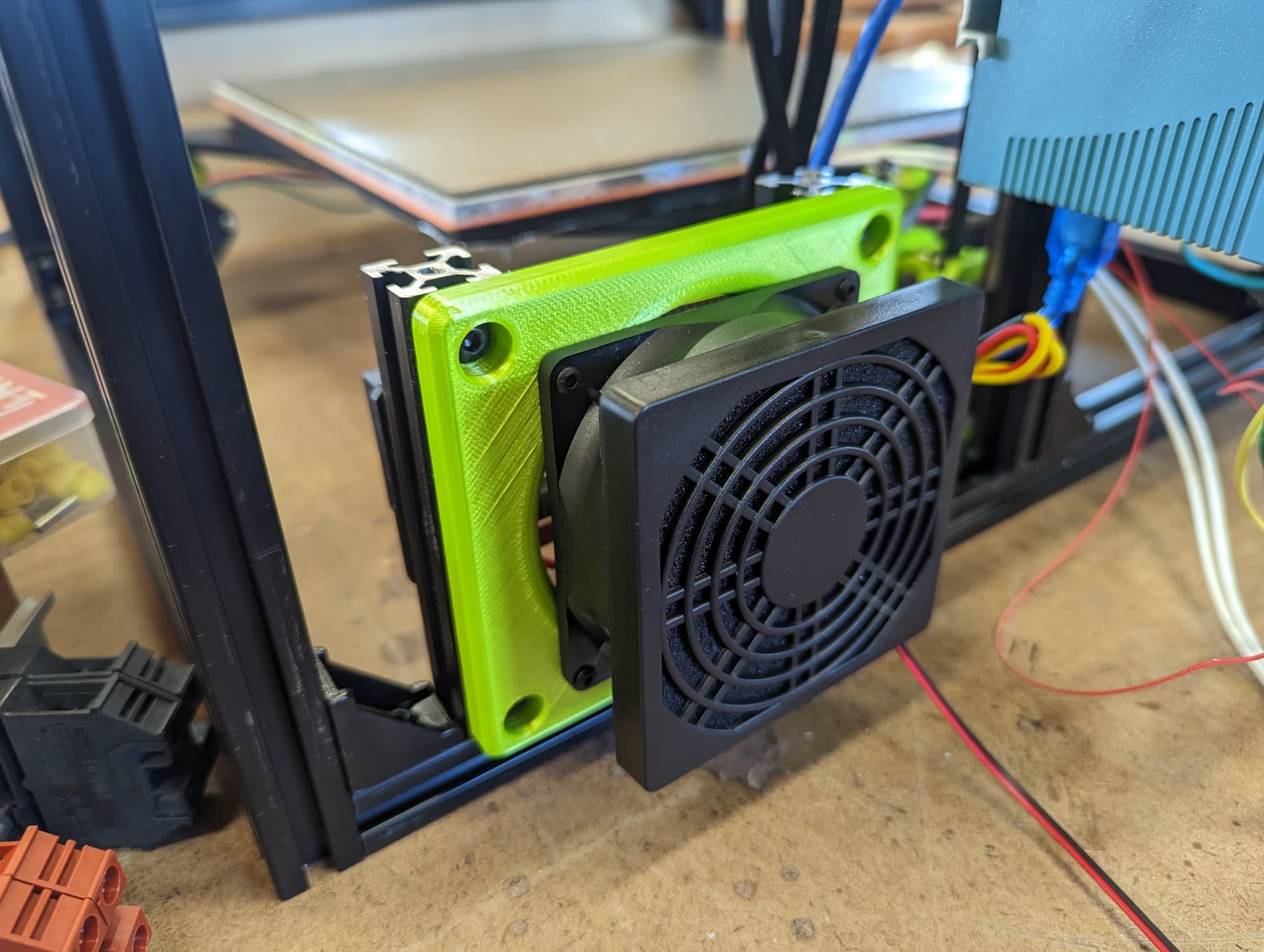
At lunch, I went and threw the chamber heater onto the machine. This will mostly be used in the winter to help keep the printer warm, but I may use it to help print ASA and ABS. I’d like to play with some higher temperature material too, but the parts being printed in PLA will keep me from raising the chamber temperature above 55C or so in fear of the parts starting to melt.
The fan will draw air from inside the electronics enclosure that will get added on the back. The electronics closure itself will have a 120mm fan blowing air across the components keeping everything cool. I’ll have the electronics enclosure exhaust out through the printer. The fan on the heater will only run when the heater itself is on. I may need to put vents in the electronics enclosure, but we’ll see how this works first.
The chamber will also have an exhaust fan in the lid to pull hot air out if it gets too hot inside.
This is all ‘in theory’. I haven’t messed with heated chambers before. I was able to write my own Octopus plugin for the chamber heating/cooling, so if it doesn’t work how I think it should, I can modify it myself ![]()

I think I did the math right and that my AC distribution plug should be able to keep up with all this wattage without melting.
The AC distribution is rated at 10A@300v.
I have the following devices running through it:
24v power supply
5v power supply
750w bed heater
300w chamber heater
Never even thought about separate chamber heater. Have been hoping that heater bed plus insulated enclosure would avoid need for separate chamber heat?
Fan to exhaust fumes/heat is a nice idea, adding my list. Cheers!
I think I mentioned it further up in this thread, but I have an exhaust fan on my current enclosed printer. It works really well to keep the temps down for PLA and it helps to cool the heated bed faster when the print is done.
The current printer has a gap around the door where the exhaust fan pulls air from. The air gets pulled directly across the heated bed.
I might end up putting 2 fans on this build for exhaust. The chamber is larger.
1 Like
I did the same thing! Glad it wasnt just me! LOL
My son’s soccer practice got canceled, so instead of mowing the lawn like I should, I worked on the printer.
I got one side plate installed. I got the other side plate and back cut out.
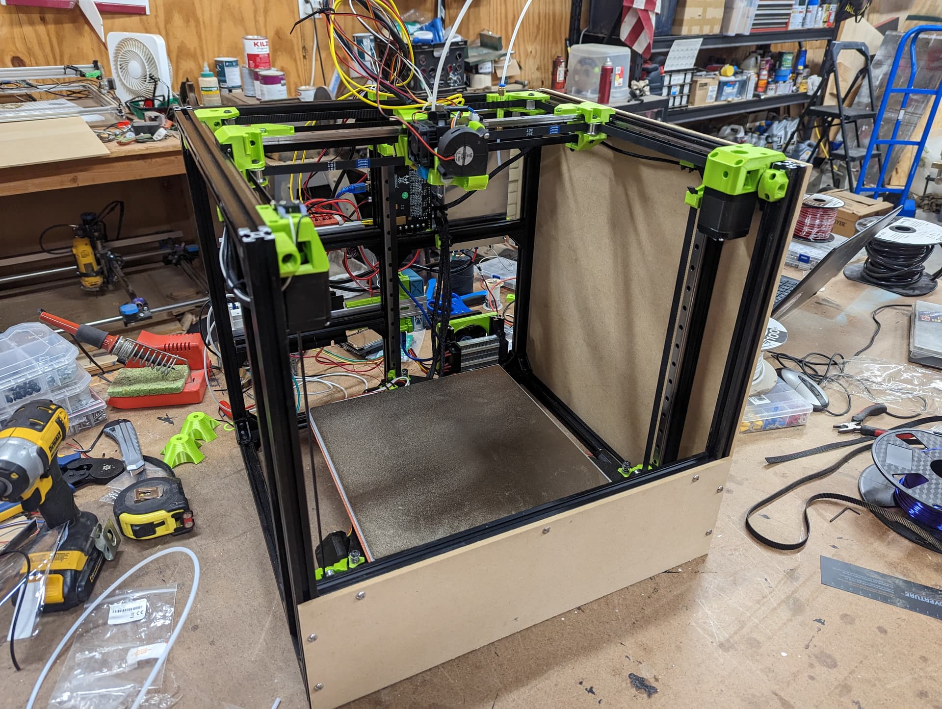
I extended the last servo and endstop. Then I tried my hand at cable lacing.
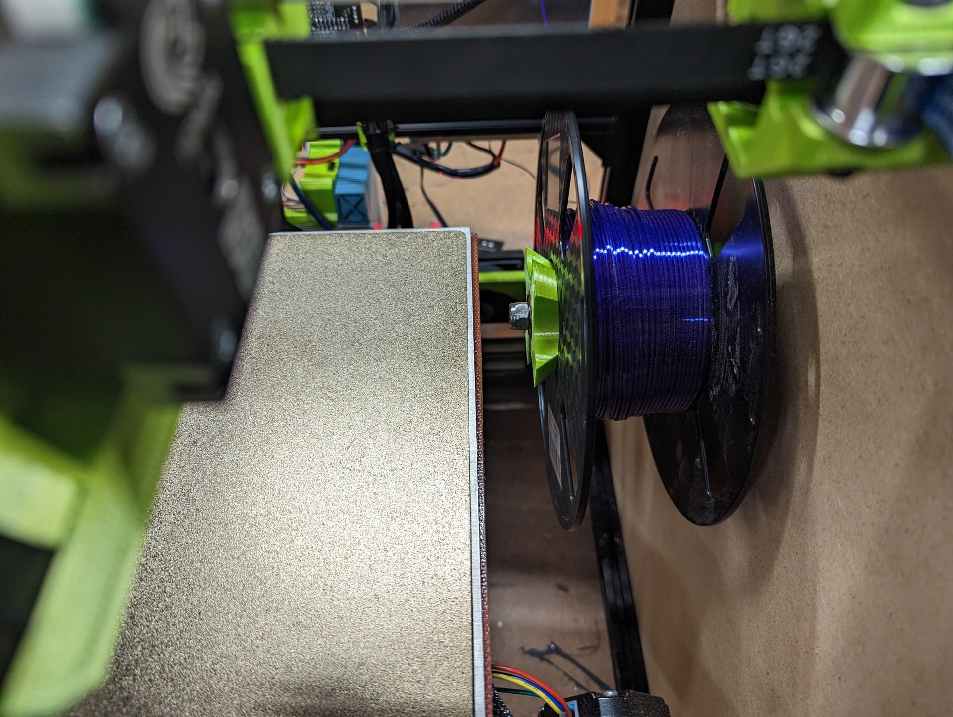
For those not following other threads, it was discovered that you can fit a roll of filament inside the printer, so I designed and printed a reverse boden mount to go in the back corner of the printer.
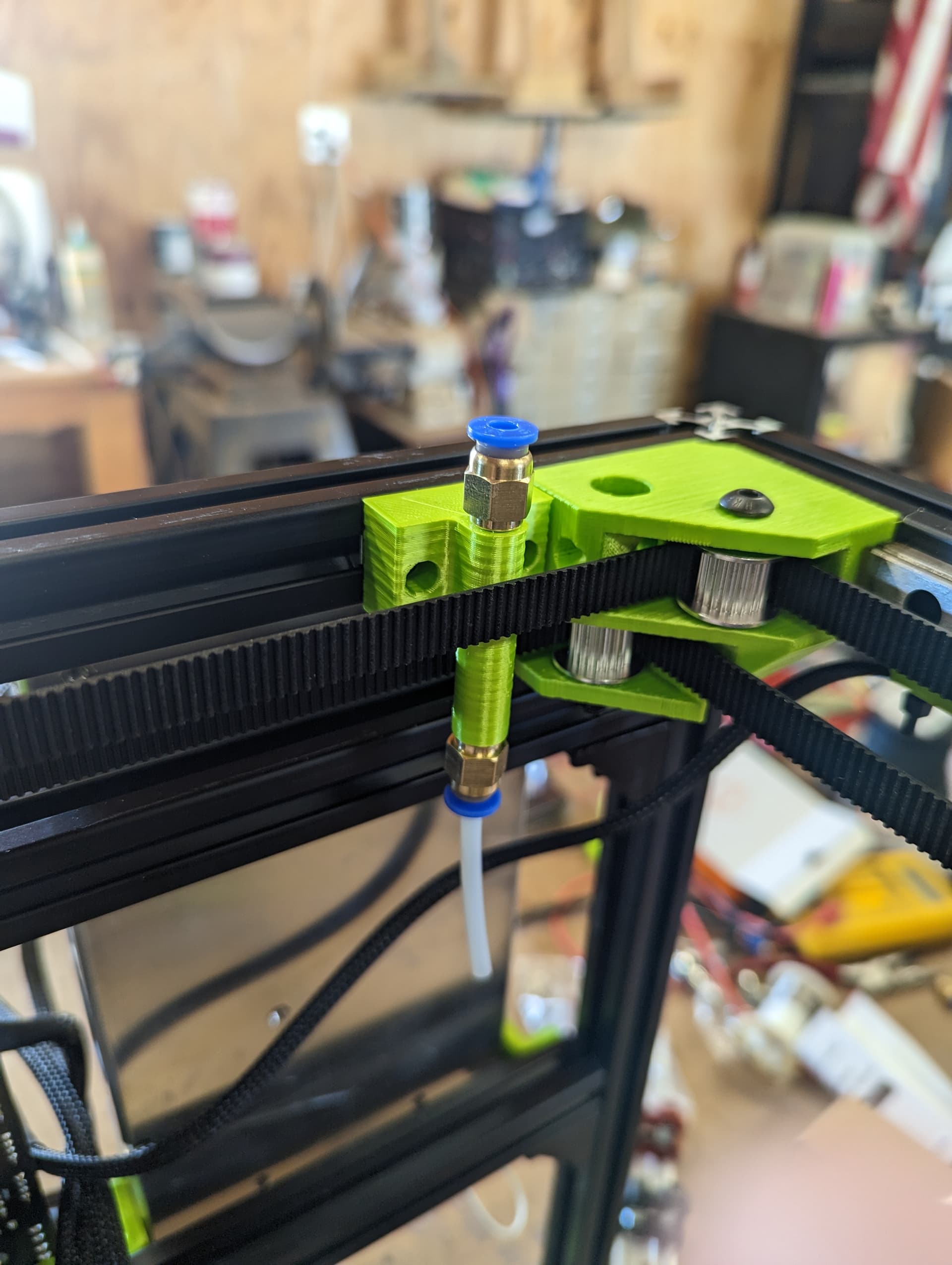
Here’s the part on thingiverse
4 Likes
Mental note… When extending wires, make them stupid long.
I extended the parts fan wires to what I thought was more than adequate. By the time I finished cleaning up the wire bundle, they’re about 3" too short ![]()
2 Likes
Every time I break out the DuPont crimper that works 90% and still needs some persuasion with pliers to make it work. I think I rather just get a USB soldering iron, so I can just cut to length somewhere in the middle. Some sort of tiny terminal block might be okay but the right length wires look so good.
As much as I love the plugs on the boards, I rather have some sort of screw or push terminal. Then we could very easily run wires. Like on the stepper side and the board side. I love clean wiring, and this is very annoying to me.
- I wonder if we could come up with some sort of dupont to manual terminal…
1 Like
The fan doesn’t use dupont connectors on the SKR. But I am using the little terminal crimps on the ends of the wires. I can easily solder on a few more inches to the existing wires. It’ll be hidden inside the enclosure.
I need to extend the x-axis endstop too. It reached prior to wrapping the wires, but it was more of a stretch than I thought it was.
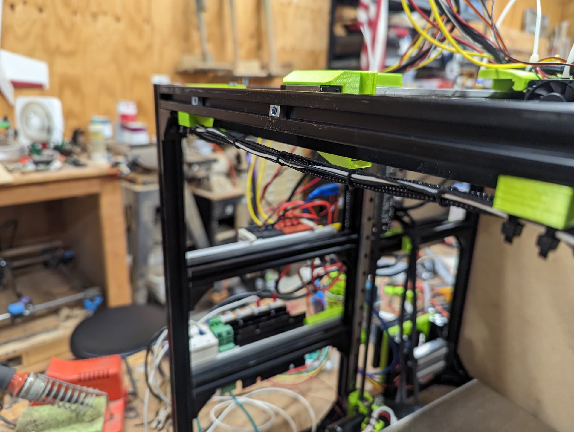
I cable laced the wires going to the extruder to try it out. It looks pretty good, but I think I’m still going to slide a wire sleeve over the entire length. I’m not a fan of seeing all the different colored wires.
2 Likes
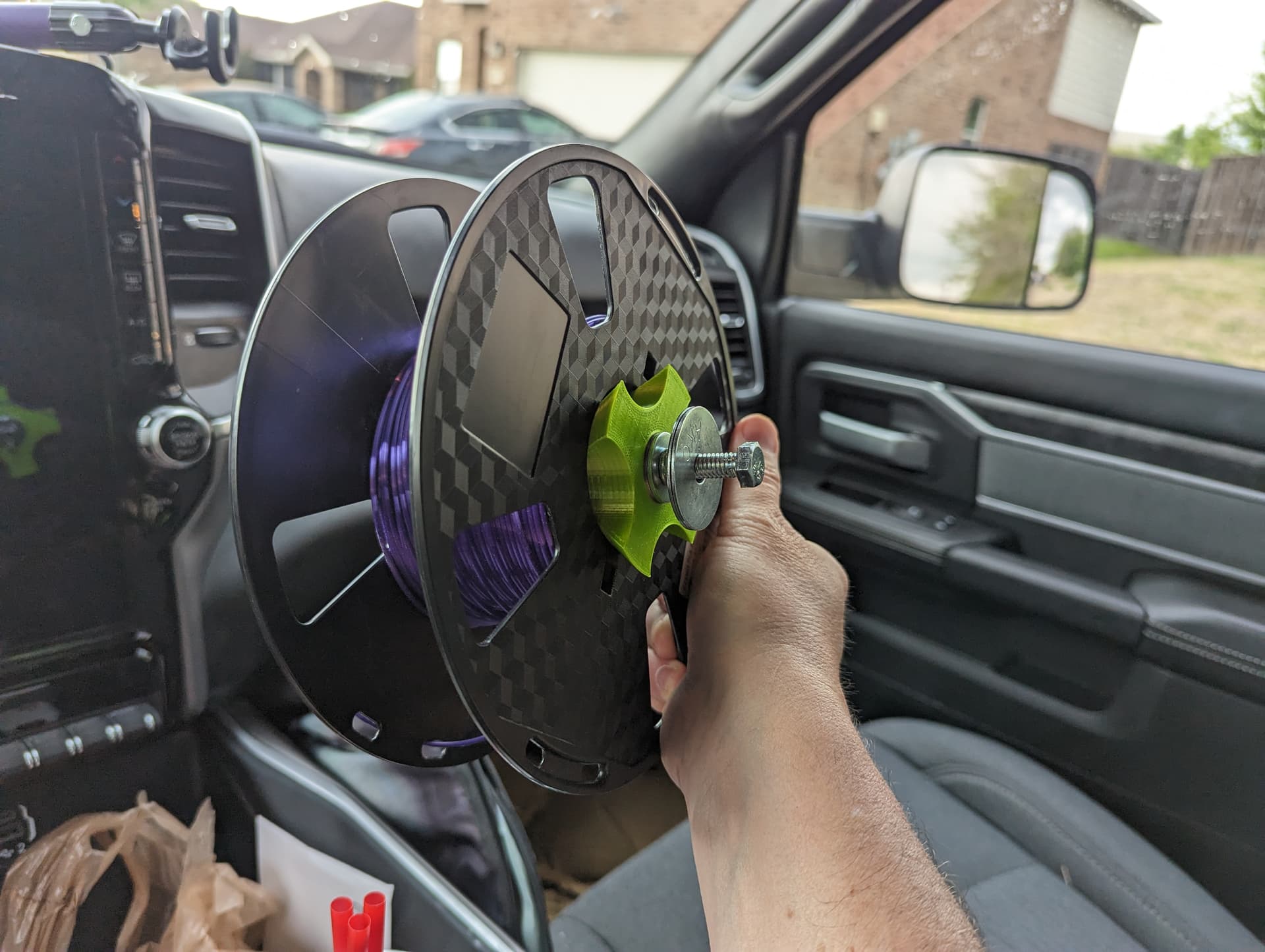
This is my plan for hanging the spool inside the enclosure. I’ll run the bolt through the side panel. I’ll use fender washers to spread the load and a locknut to keep the bolt on the wall. Then the spool will be between two regular washers and a wing nut loosely used to keep it on. If the wing nut doesn’t work, I have a second locknut I’ll 3d print a large gear to use to turn by hand.
Looking at mine I am concerned about the bolt sticking out too far and impacting the bed. Thinking about literally putting one of the bearing ones on the bottom plate and seeing what happens.
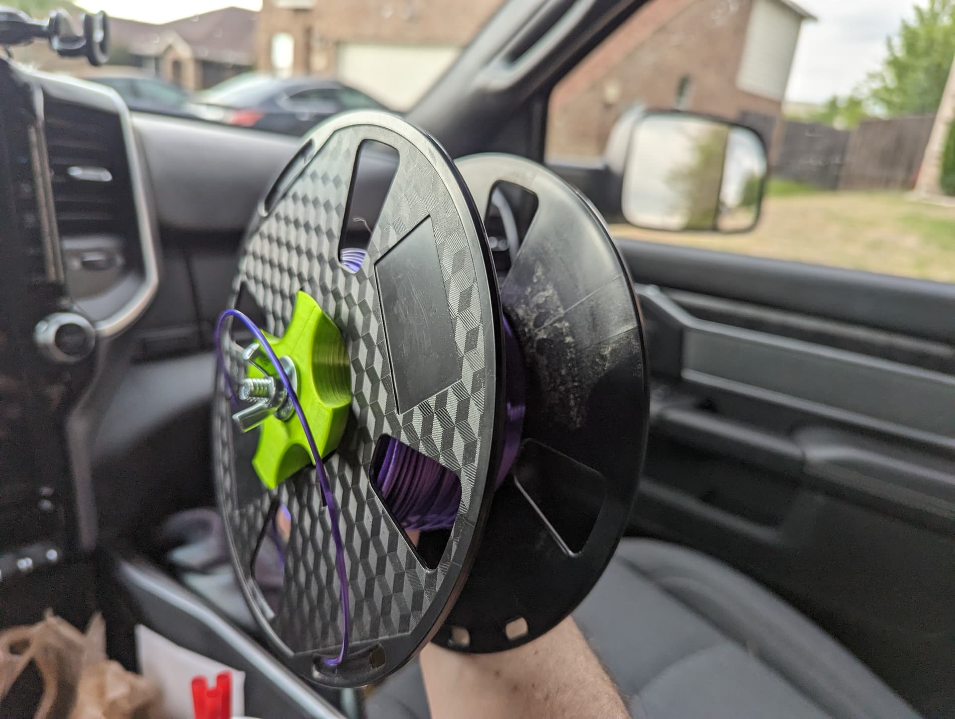
Yeah. So… about that.
The bolt I bought was too long and the bed would hit it. But, I bought a really long bolt. So I chopped some off.
Problem is. I chopped too much off.
I had to remove the lock nut that was up against the side wall. So it goes, bolt, fender washer, side plate, fender wash, regular washer, filmanent holder, lock nut.
It looks like it will still work. I can get another long bolt and this time only cut off enough to clear the plate. I have nearly another half inch between the end of the bolt and the bed now.
1 Like
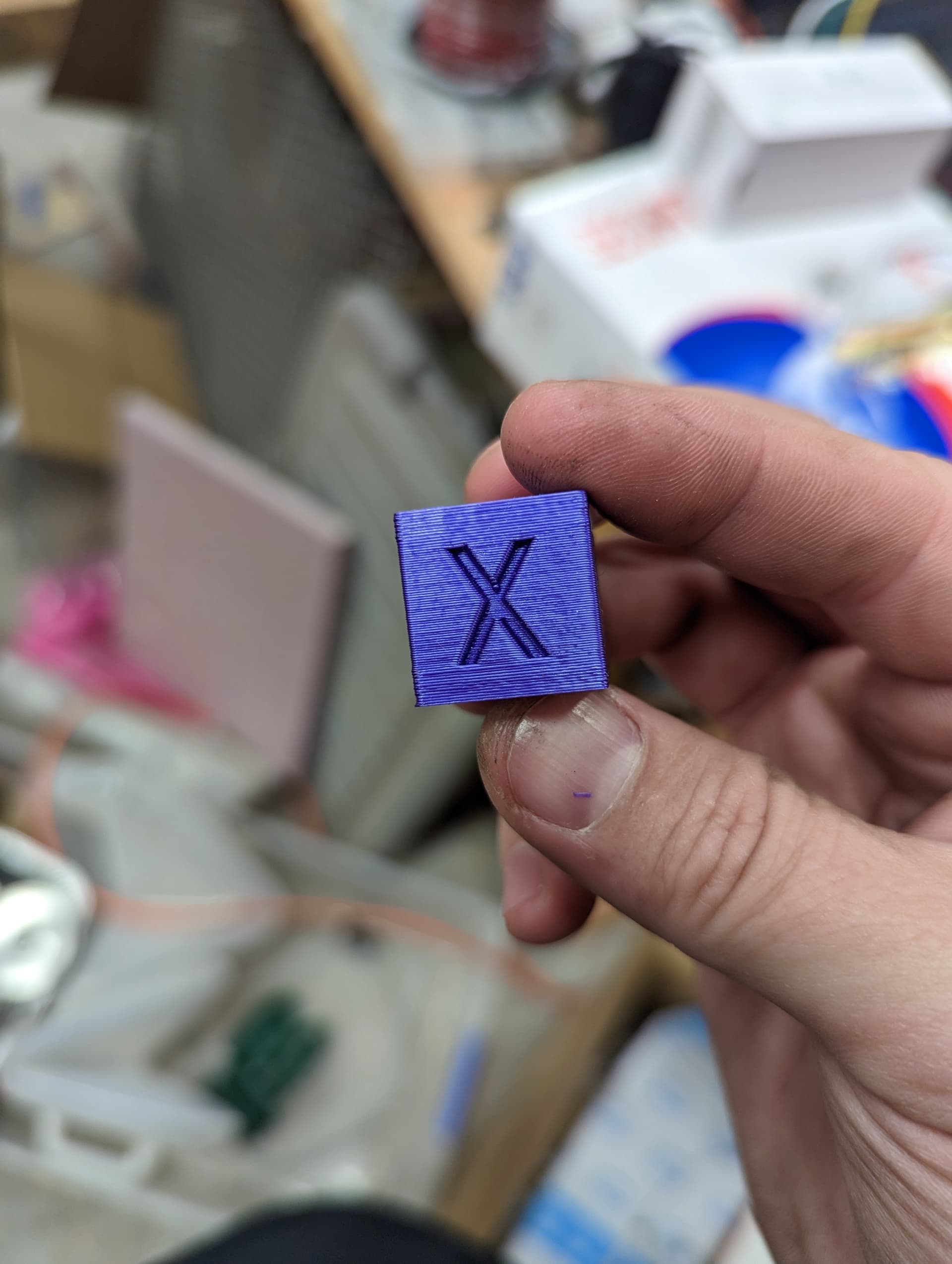
It’s alive! Best first print I’ve ever had.
Completely untuned in s3d. I took my existing printer profile and just changed the startup commands to do the bed leveling.
The calipers show the dimensions are just about perfect. I did not test for squareness.
I have a video uploading to youtube complete with a bed drop at the end when the steppers shut off.
Here’s the first print pictures. I’m really excited to get the printer finished now, calibrate it, and get appropriate speeds configured in my slicer.


5 Likes