This is my first venture in CNC. I started 3D printing with an Ender 3 about 3 years ago. I dabble in woodworking and electronics (ESP 01/8266/32, Arduino, etc) among other things. Professionally, I’m a software engineer. So, I have some useful related experience. If you ask my wife, my hobby is collecting hobbies.
Overall, this has been a lot of fun. Sure there’s some frustration mixed in there, but it’s wild that a person can have a machine with this kind of capability at this price.
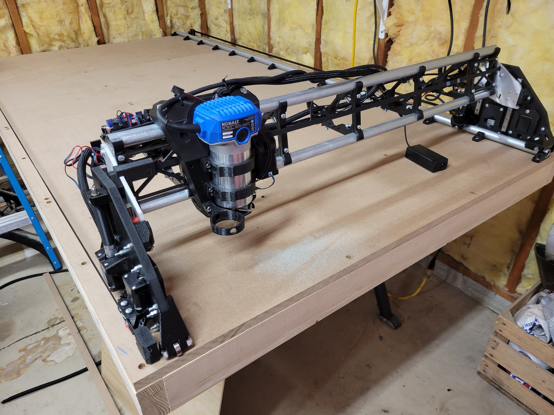
Specs
Working Area: 34.5" x 75"
Table Size: 49" x 90"
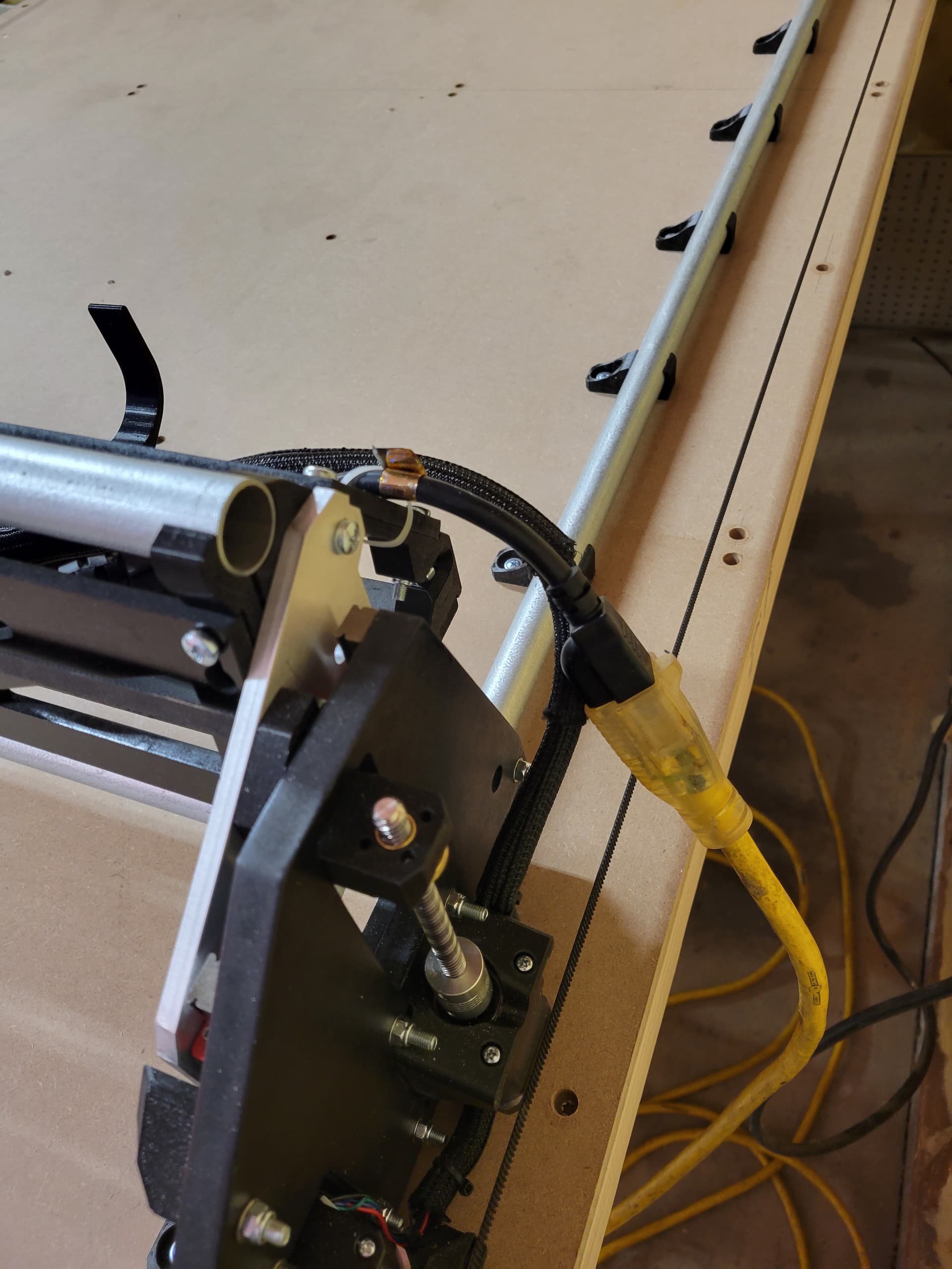
Rails: 3/4" EMT
Board: Jackpot v1.1
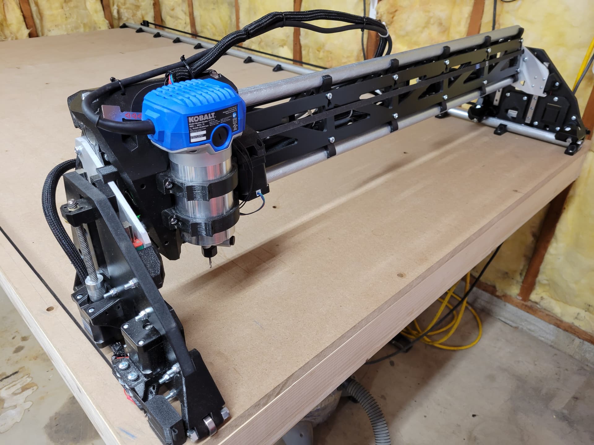
Router: Kobalt
Parts: All sourced from V1 store (including printed parts)
Table Details
Status
- Table Built
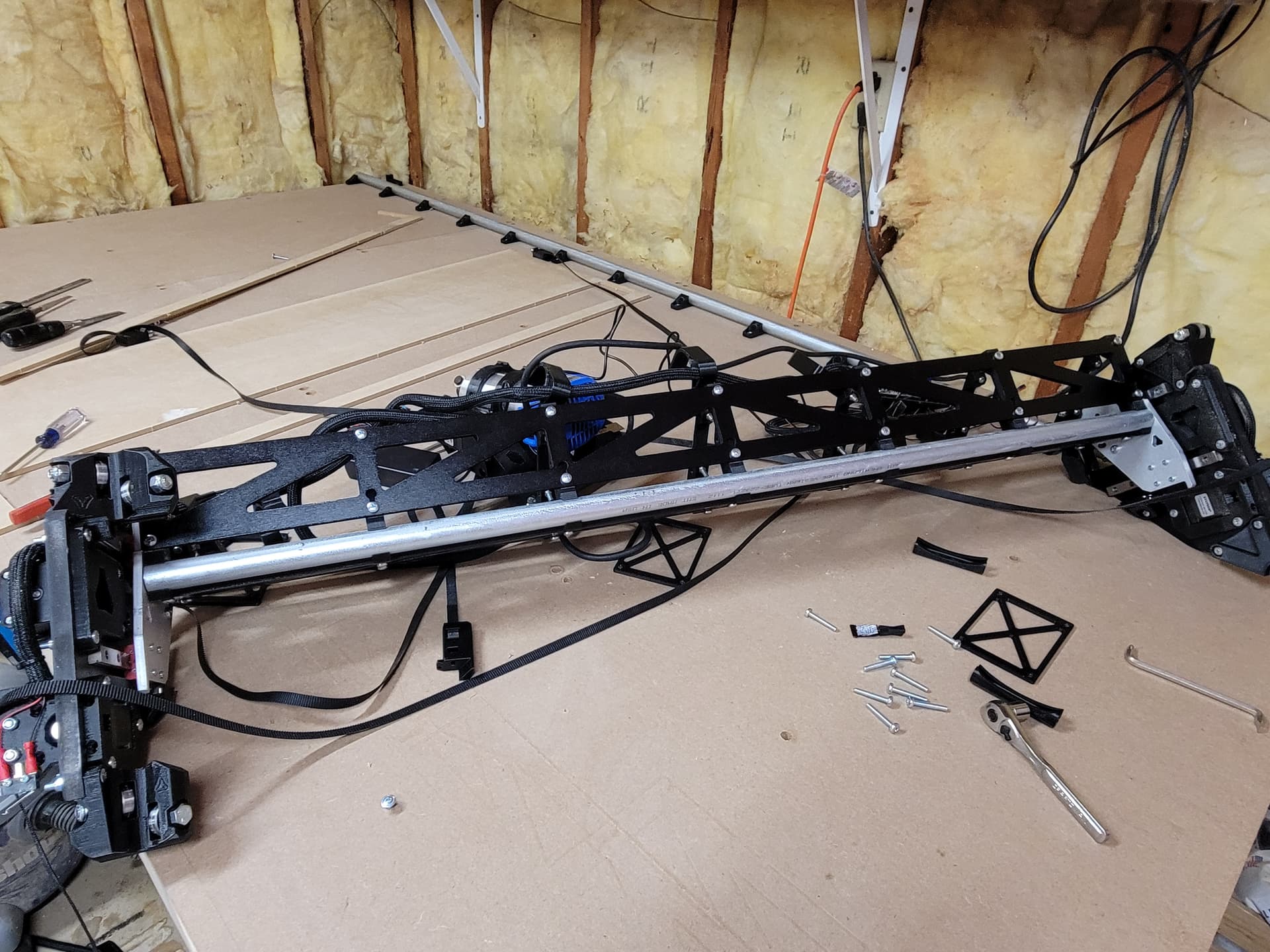
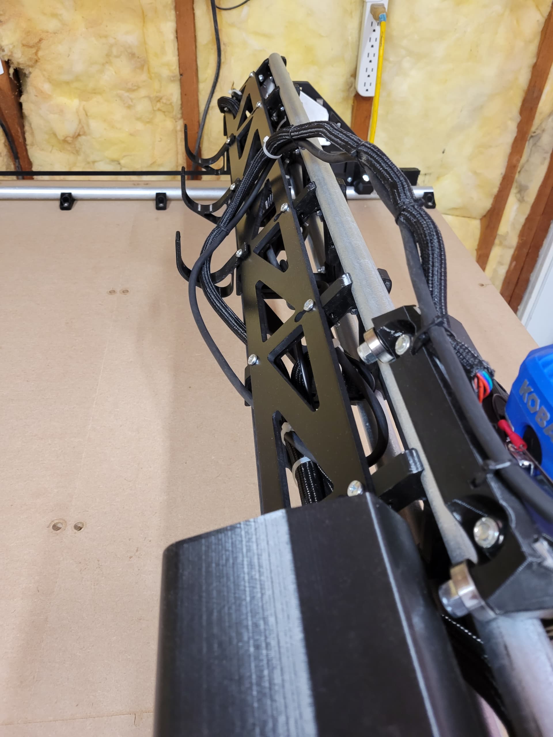
- Gantry Assembled
- Wired
- Crown
- Router Mounted
- Squaring and Z Leveling
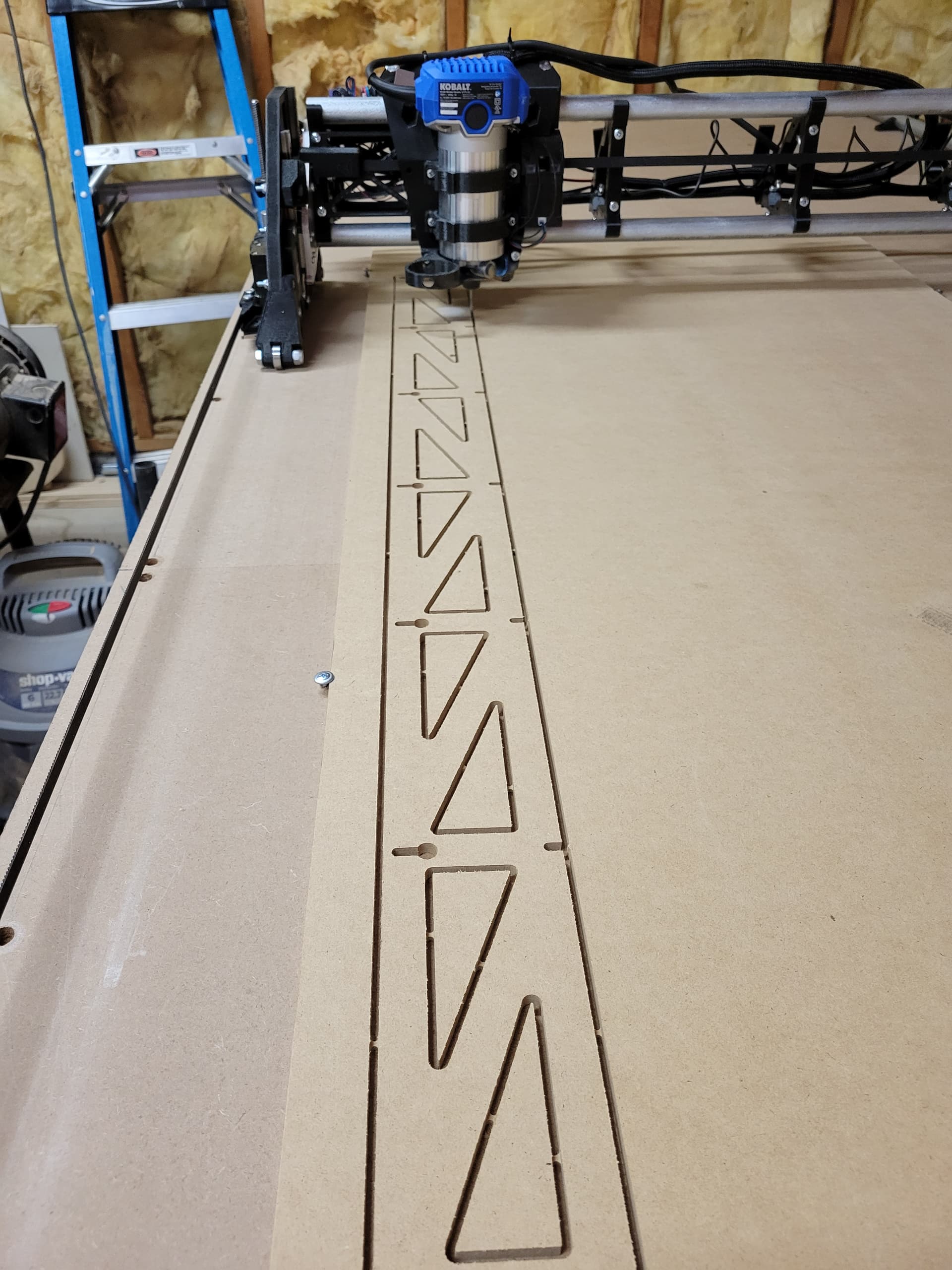
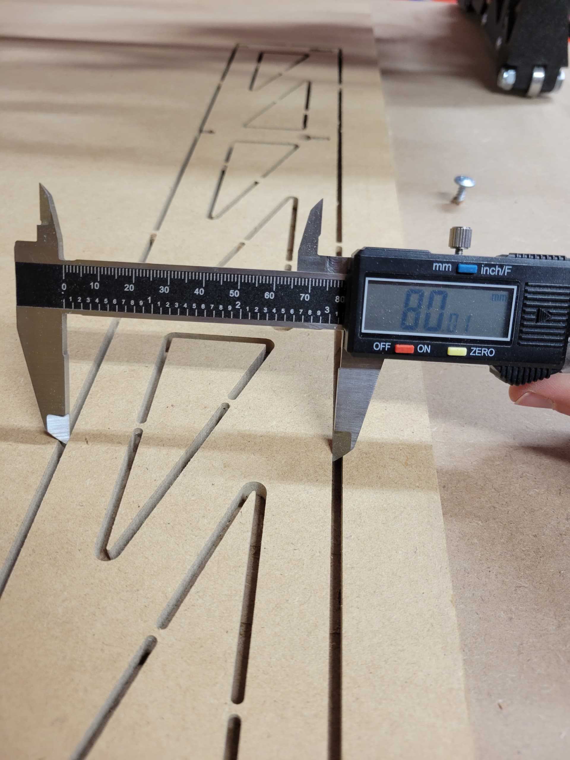
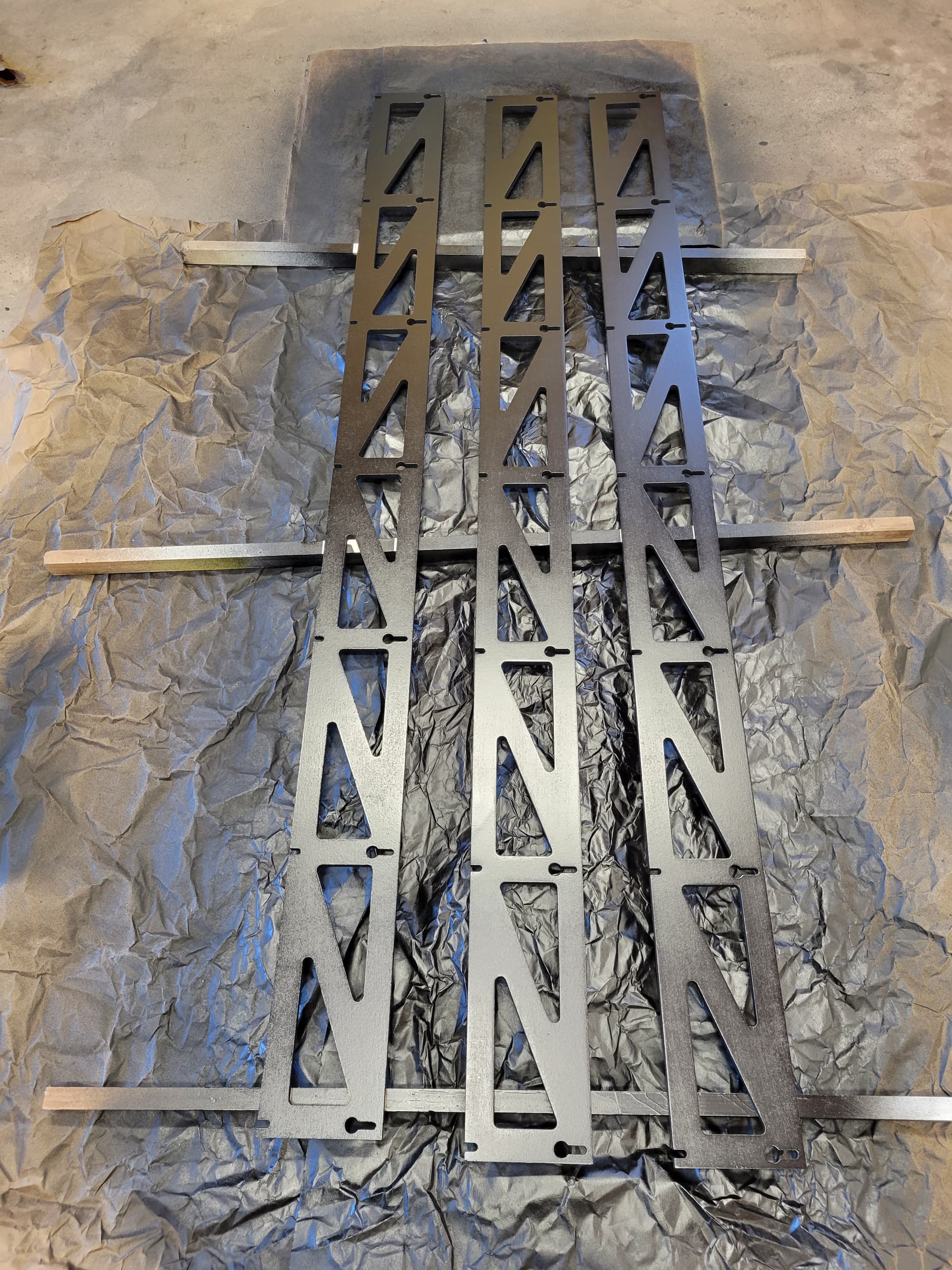
- Strut Plates Cut
- Strut Plates Installed
- Wiring
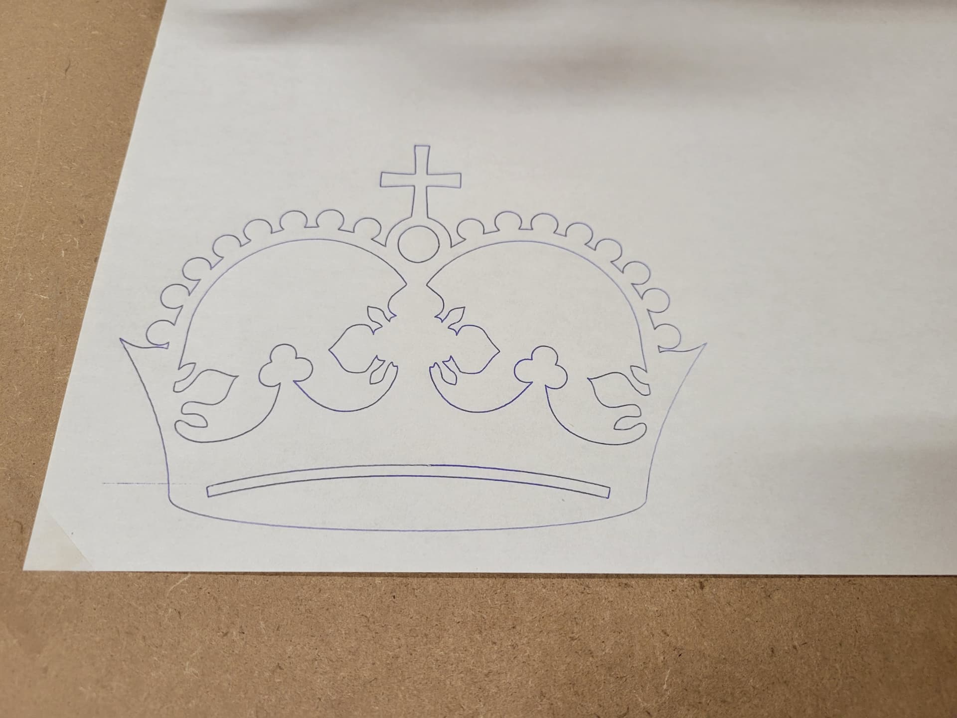
I did the crown before Z leveling so I expect it would be better now (the right side is a bit light).
I was super excited that after squaring, I can’t even detect a difference between the diagonal differences with a tape measure. Surely less than half a mm.
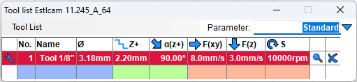
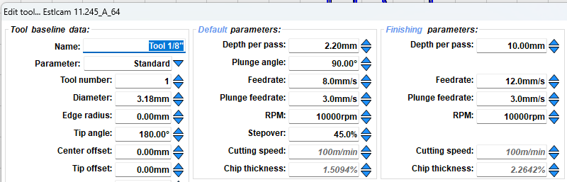
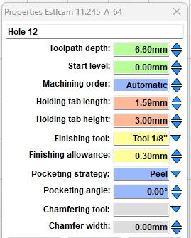
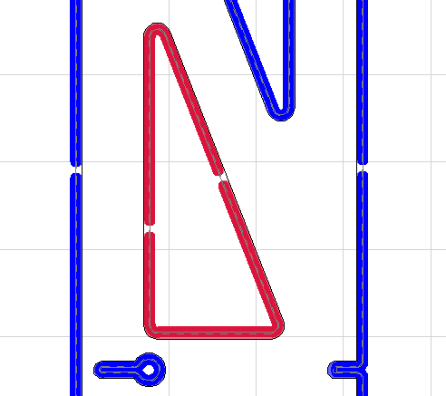
I was playing in foam. I created the letter Y in Inkscape and created the gcode in Estlcam. After I play around a bit more, I’ll cut the strut plates.
My Kobalt router seems to have an issue where the RPMs don’t stay consistent. They’re ok at setting 1 but they seem to waver at other speeds. It seems that it will stop doing that after a bit until you change the speed again. We’ll see if that resolves itself, otherwise I’ll swap it for a new one. I saw someone else had the same issue.
I need to sort out some wiring organization but I’m waiting until I get the strut plates cut before going too crazy. I’m curious how others are handling the power cables. At some point, I’ll setup a vacuum, but not ready for that yet. I want all the power cables and eventually the vacuum hose at the back (Y rail side).
I do think the instructions need to be updated to better document the Jackpot. Some of it is answered on the Jackpot specific page, but the main instructions don’t reference it and things like squaring and Z leveling work differently than how they’re defined in the main instructions. Commands like M114 and M666 don’t work on the Jackpot.
It took about 3 weeks working on and off to get to where I am now (playing in foam). I was pleasantly surprised at how quickly it came together. I have about 2 weeks off work around the holidays, so I’m looking forward to diving deeper into this.