New LR3 Build end stops, probe and homing issues

Hi All,

I have been searching the forums and the docs for info on how to get my system running. It’s all assembled and I have basic movement and have done a drawing with cncjs connected by USB.

I am using the skr pro v1.2 (idk if it has the wireless) see attached photos for the firmware, 2.1.1 I think. 24volt power supply.

I have the dual end stops/limit switches and a touch plate connected. LED lights on the board light up when I depress the limit switches.

I have only wired the resistor pigtail to x-axis which I thought I wired incorrectly at first and then corrected as I thought I might have damaged the board.

There is definitely weird stuff going on with the end stops as sometimes they show as triggered and other times not when sending M119. Even now the z-probe is saying it’s triggered but it is not in contact. Even after board reset. See photo.

Are the issues I am having related to firmware or the board and the low voltage for the board logic, (i.e. I have to make the 1.5k resistor pigtails for all end stops)?

This is the main issue I am experiencing which means I cannot home the machine.

The other issue which we could address later is z-probe function in cncjs raises the z-axis instead of lowering.

If anyone has any answers on how I can resolve the endstop/homing issues I would really appreciate it. Thanks

Hello Geoff.

Don’t worry, we’ll get you sorted out.

You haven’t told us what machine you have. I’m going to guess from the picture that you have an LR3 (or LR4) and not an MPCNC. My comments below may or may not be correct for the MPCNC, but should be correct for the Lowrider.

Edit - Duh - it’s in the title, sorry

This is a good sign

There’s two issues that can cause intermittent end stop problems.

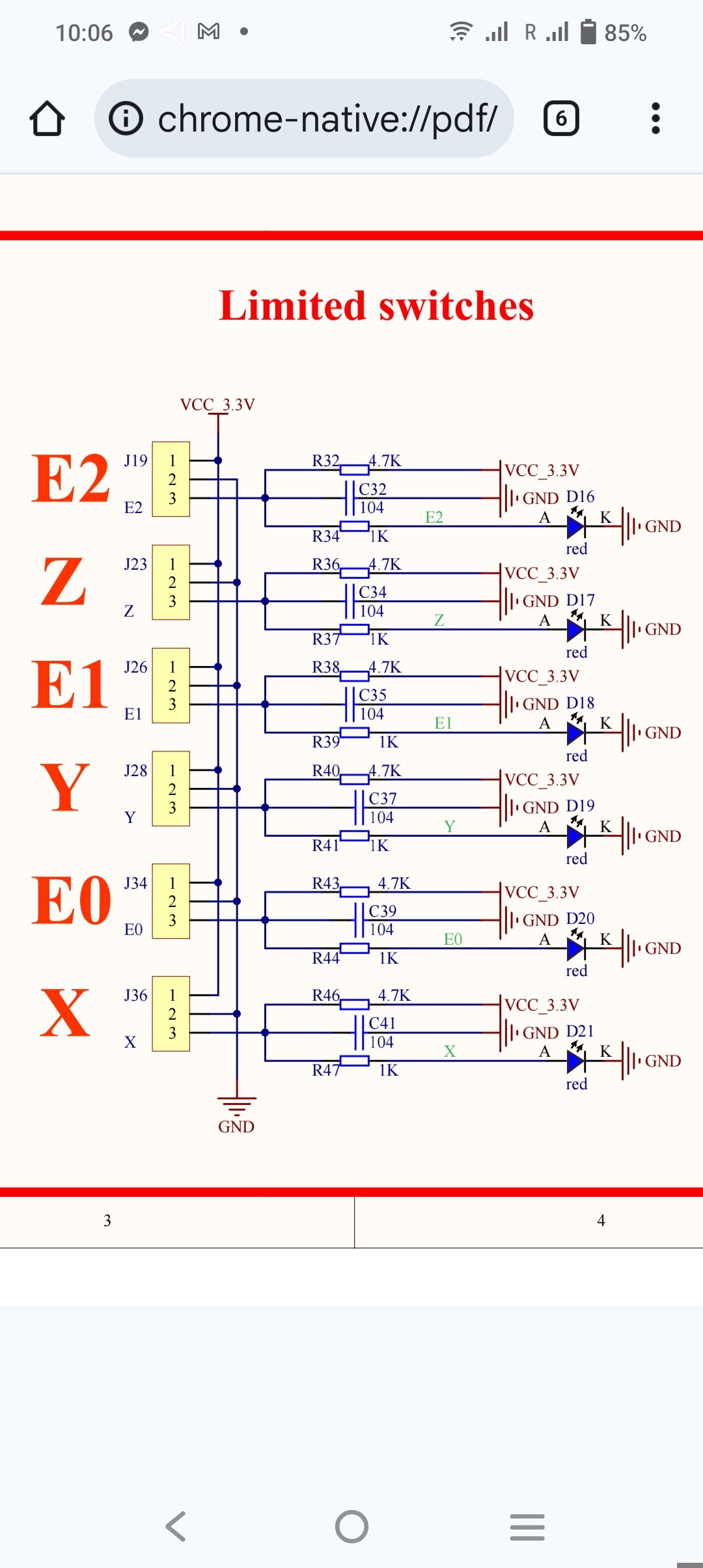
The first you have identified - the infamous SKR Pro v1.2 end stop circuit design, which can usually be corrected by either adding pigtail resistors, or by cutting out the LEDs.

The symptoms are the LEDs will show as triggered when the switches are asserted, but the M119 won’t detect the triggered state. This often results in the motion not stopping when it should, with skipping steps and a grinding noise. If this is happening, it is usually best to add resistors to all 5 end stop circuits, but you may get by with just adding them to the circuits affected.

This issue can be affected by such factors as the length of the circuit (and hence resistance) to the end stop in question. I had a board that worked fine with a shorter gantry, but when I lengthened the gantry and soldered in an extension cable, the issue started happening regularly.

I don’t think that this is your issue.

The second issue is an intermittent open circuit, usually at the connection of an extension cable, but sometimes at the switch itself (especially with spade connectors) or at the Dupont connector on the control board.

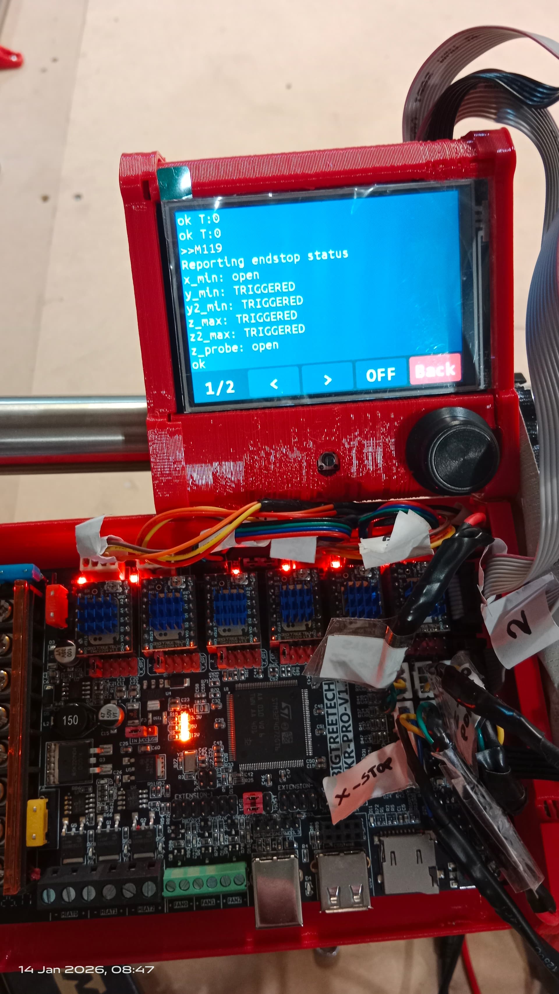
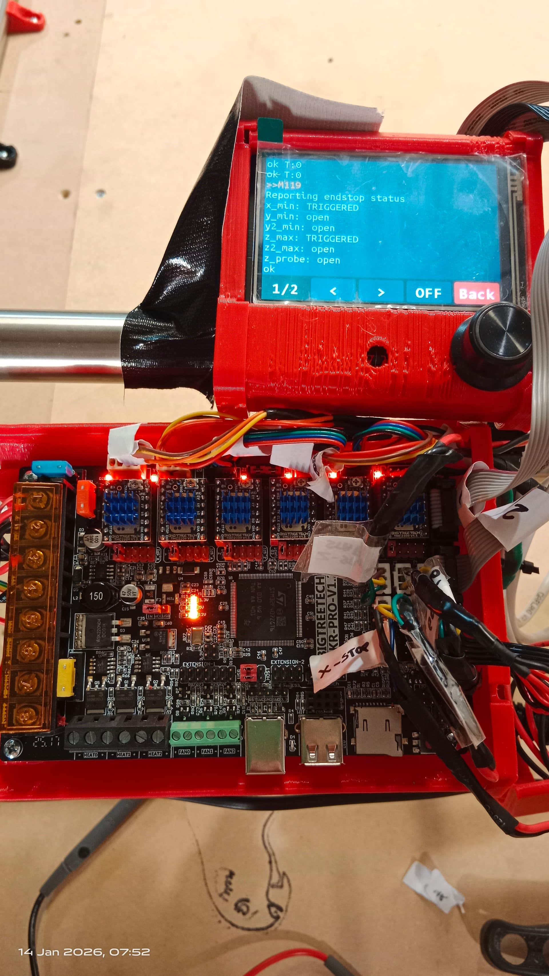
The symptoms are very different than the first issue. In this case the switch will sometimes show open (LED Off, M119 Open), and will work properly when asserted (LED On, M119 Triggered). On other occasions, it will show as asserted (LED On, M119 Triggered) even when the switch is not asserted.

This sounds like possibly the second issue. If an end stop is showing triggered when not asserted, it is usually an open circuit in the wiring. An intermittent open is usually a bad connection somewhere.

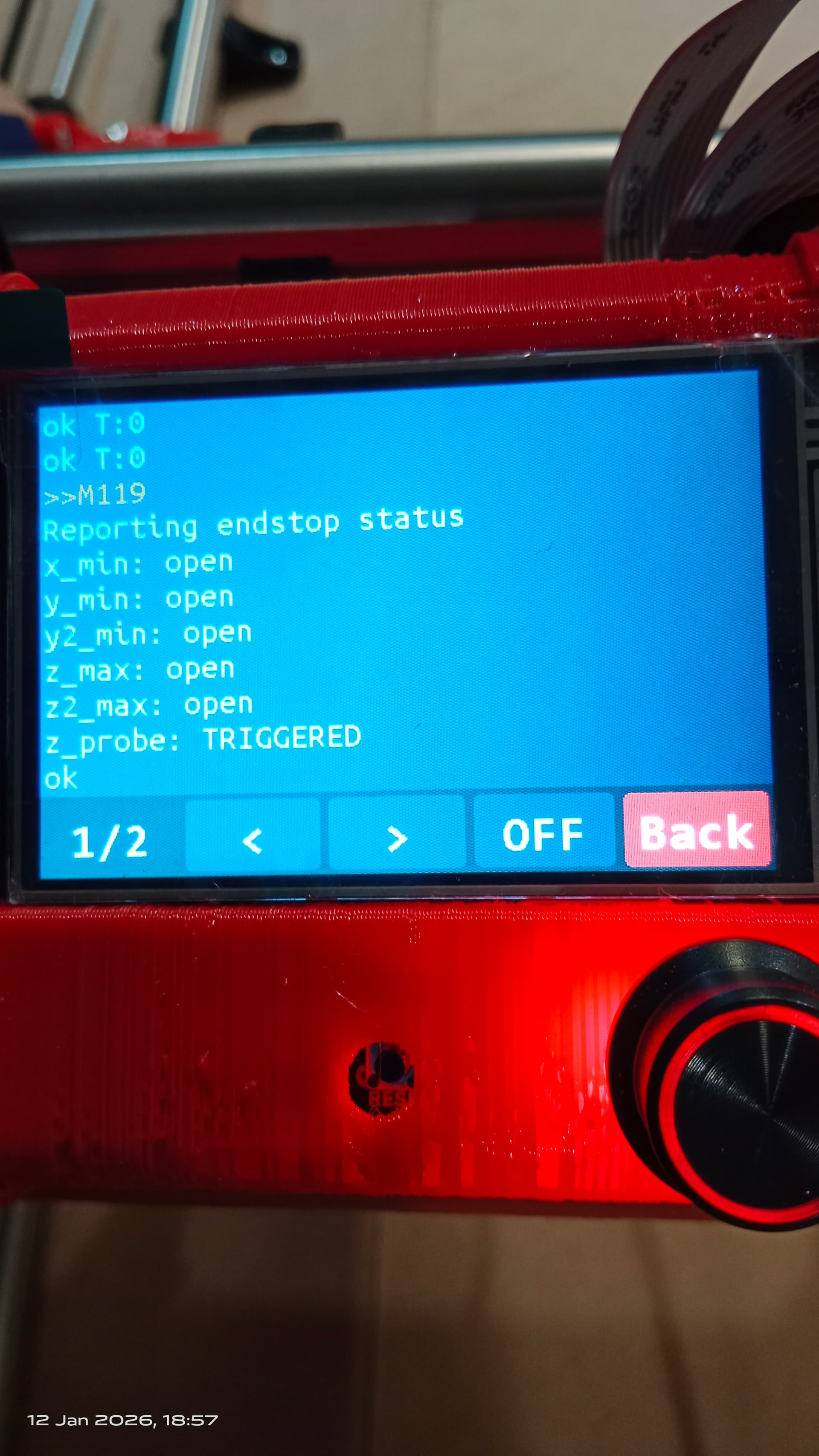
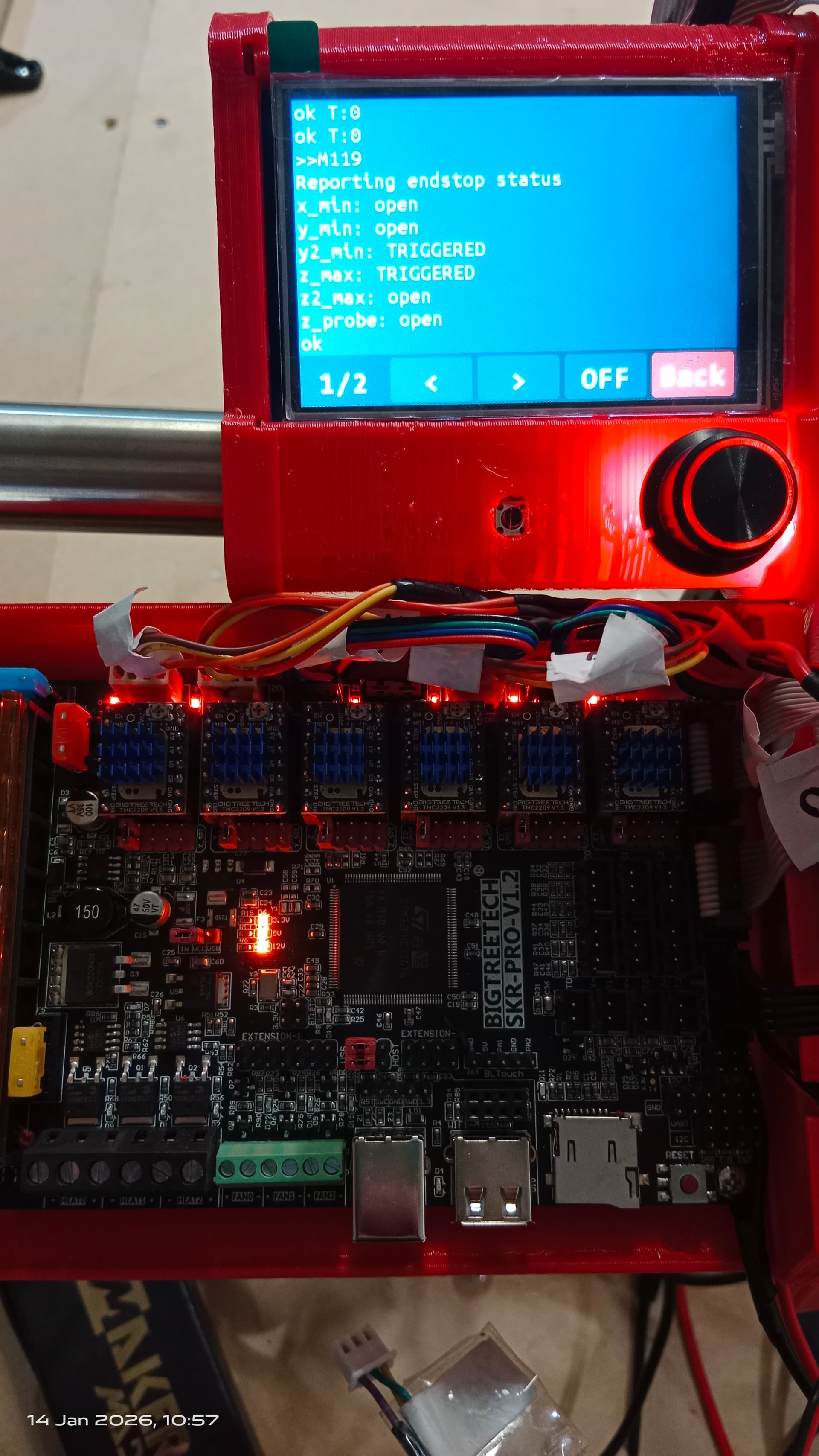
That shows all 5 end stop switches (X, Y0, Y1, Z0, Z1) as open (not asserted) and the Z Probe as Triggered. It may be possible that you have the alligator clip contacting the touch plate when you are sending the M119 command. Or it may be possible that your Marlin config is incorrect. The Z probe triggers on Closed, while all the end stops trigger on Open.

Run the M119 command with the alligator clip attached to the probe, and then again when it is not attached. If it shows Triggered when attached, everything is working fine. If it shows triggered when not attached, the config is probably wrong. If it always shows triggered (in both states), then there is something else happening that will require further investigation.

With all 5 endstops showing as open, you should be able to home all three axis. The Z probe is used later for setting the Z height at 0 at the top of your stock.

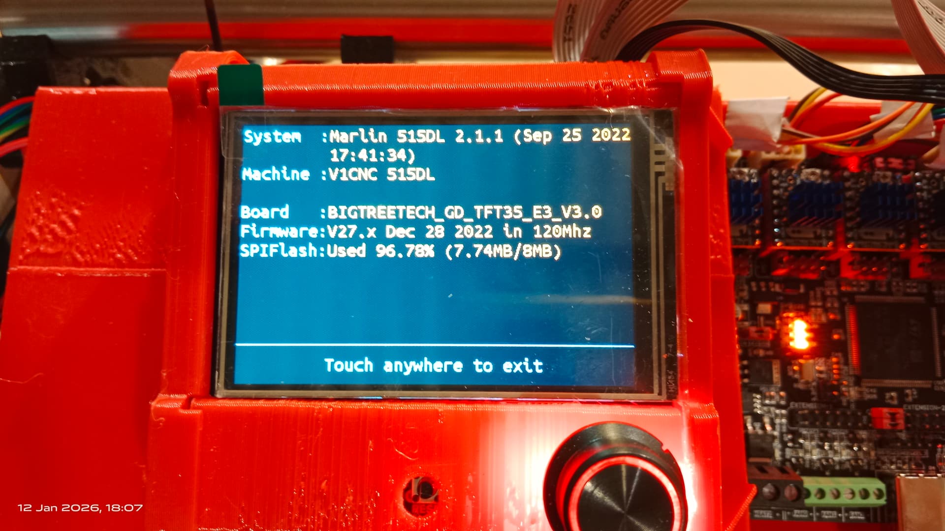
Not sure what you mean by CNCjs. The photo shows you are using Marlin.

A Z probe (G38.2 Z0) should lower the Z axis. If you have not homed Z yet, that may be the problem.

When you start the machine, Z=0 at whatever location you are at. When you home the machine, it should set Z=200 at the top of the travel.

The G38.2 Z0 command will move toward 0 from wherever it is. So if you are at the top of the travel and Z=200, it should move down. If not, there is a configuration issue in Marlin. HOWEVER, if you haven’t homed, and the gantry was at near the top of the travel when you started the machine, and later moved the gantry lower (Z=-n), then the G38.2 Z0 command will attempt to move upwards toward 0.

Let me know if that helps.

1 Like

Ok, I missed that in my earlier comments.

I suggest that you use the touch screen for all troubleshooting purposes and homing/Z Probe commands, and that you run any gcode from the SD card before you introduce a web GUI/USB interface. At least for the first several uses.

Once you have everything working 100% with a stock build, then add the interface. That way, any issues that arise will probably be with the interface, and not with the controller or wiring.

2 Likes

Thank you Bartman for your assistance and a very comprehensive reply.

Yes this happens when i ran the homing program and just running out the axes to the endstop. However, I read a post somewhere that “the firmware only cares about the end stops when running the homing program”. Does that mean the endstop function will only kick in and stop the motors when running the homing program?

I can do that and report back.

I have 3-pin JST connectors, with only two pins installed on G&S (will add the third for the pigtail solution) but not dupont. Except for the touch plate, i have two of the arduino-project-type over the G&S pins.

I figured if the LED’s illuminate, assume continuity.

Ok so, on the Y axis I depress/assert both endstops and send M119; only one comes back as triggered, yet both LED’s are illuminated on the board.

And so is there a correct/approved diagram for wiring said pigtails? My first post was in relation to navigating that information in search for diagram that correctly shows the wiring in documentation, rather than a referenced discussion containing both correct and incorrect wiring diagrams, which may or may not be confusing to a new reader like myself.

I’d rather not modify the board for warranty reasons but now having wired the first pigtail incorrectly (potentially damaging the board) that maybe irrelevant.

Thanks again.

Yes, that is the case.

Not if the SKR resistor issue is happening

That is a classic example of the SKR resistor issue

Yes, there’s several threads that show how to wire it correctly. Unfortunately I am on my phone at the moment, and can’t search for a link easily.

If you can wait until tomorrow morning to I’ll post some links and some more information

There are two ways to add a resistor to the circuit.

One way is to solder a resistor directly between the the leads on the underside of the board. If you are confident in your soldering skills, this is an ok way to go, but as noted in one of the linked posts below, it will void your warranty.

The other way is to fabricate a pigtail. If you don’t feel comfortable with your soldering skills, then the pigtail is a good choice. Plus it won’t void your warranty.

There is a third option of breaking the LED, but you lose the visual indication and it definitely voids your warranty.

Here is a post that links to some background information

In either case you want to connect a resistor between the two outside terminals (5V VCC and SIG)

Here is a post of mine where I summarize the options

It links to another thread that has a hand drawn schematic of how to electrically make the pigtail

Here’s another post of mine in the same thread that has a bit more info.

From a different post in the same thread:

“MAKE SURE that the 3 pin connector is attached so that only the resistor (and not the resistor and wire) is touching the VCC pin on the board, or you can permanently damage it”

Here is a post that shows how to physically make the pigtail.

There’s a way that you can check if the board is working or not. Firstly check that all 3 VCC LEDS (orange) are on. Then jumper the two pins on the 2 pigtail 2 pin connector (the side that connects to your end stop switches), or simply connect the endstop wiring to the pigtail and assert the switches.. If the LED asserts and the M119 shows Triggered on every end stop circuit, then it should be okay.

Hope this helps

1 Like

Ok, reporting back after installing 1k5 (1.5k) resistors across 5v (x) AND SIGNAL on all endstops at the board end.

There is something really screwy with the board or firmware. I will try and document all that I did and the results.

All resistors installed across 5v (x) and signal.
Removed z-probe.
Ran out the x-axis to trigger the X limit-switch, LED on the board illuminates. (did NOT run Home program).
Send M119: result = ALL endstops OPEN.
Run Home Z program: results = Left side Z continues to grind after endstop reached, Right side Z reaches endstop and drops suddenly. Ran Emergency Kill function.
Reset board and/or power off/on.
Send M119: results = X endstop=triggered (nothing for either Z-axis endstops)
Jogged Z axis until both were nearly level
Jogged X-axis away from X endstop switch
Ran X Home Program: results= both Z-axes lowers. (??)
Reset power and/or power off/on
Repeat Z Home program: results same as before
Send M119: result Z-probe=triggered all others open.

This is truly bizarre which makes me think it’s something with the firmware or board. Nothing is consistent.

Wait… Z positive is UP, Negative DOWN?

3 Likes

Yes it is.

Machine homes up to top of travel. You the. Probe down to set z0 or jog down and manually zero.

2 Likes

That is unexpected. Try removing all of the endstop wiring from the pigtails, and do another M119. All endstops should show Triggered, except Z Probe, which should show Open.

That can happen when the Z Stub reaches the top of travel and hits against the top of the YZ Plate. It will either skip steps (the grinding you observed), or will lose power and drop, then start to lift again. Mine does the same thing if the end stop switches aren’t adjusted correctly, or if I send a move command that is too large for the available travel.

That seems really unusual. The only thing that I can think of is that there was a power bump (did the Z axis lower by the motors, or did the gantry fall as if no power?)

I did have some strange behaviour on my SKR at one time. It seemed that the controller got scrambled. I unplugged everything, waited 10 minutes, and restarted it, and everything returned to normal (ghosts in the machine).

I’m wondering about the power supply. What size (Volts and Watts) are you using? What voltage level do you have at the terminal?

Also, can you provide some pictures of your board with the power on (to show the power LEDs).

Okay, so after a series of tests involving asserting all switches and trying resets and power off/on, which I won’t bore you with yet, I unplugged all the endstop wires from ALL the limit switches and send M119. All except the X-axis come back as triggered.

The reason why I think X does not is because that is the one I wired the pigtail wrongly in the first instance. I wired it like the paper plate diagram and when I connected the power I thought I heard a pop and the tiniest bit of smoke. But I could have also been hallucinating.

So I re-wired the X to the correct way as you showed in the image above. But it still does not show as triggered. Could it be that the pigtail resistor is fried or the voltage regulator or some other component related to X is fried?

In a previous test this morning it shows as triggered when asserted.

When you hooked power to the signal wire I bet you fried that pin on the board.

Yeah, you connected the 5V terminal directly to ground (through the closed switch contacts)

I’m guessing that you damaged the board. I’m not sure what, if anything, you can do about that. You MIGHT be able to reprogram things to use the Z Probe input as the X end stop, but then you wouldn’t be able to use the Z Probe function.

You might have to replace the controller. I’m a die hard SKR user (one of the last holdouts), but I wonder if a Jackpot board might be a better choice for you. There’s nothing preventing a replacement SKR board from having the same resistor issue (ask me how I know), and given that you want to use a GUI interface rather than the touch screen, the built-in WiFi of the Jackpot might be preferable.

Sorry that you are experiencing this. Frustrating, for sure.

1 Like

One thought - before you throw the board in the trash, power cycle the board a few times, and remove all of the pigtails, then run a M119. If you still get an Open (on anything other than Z Probe) with no pigtail or switches connected , then the board is probably gone. If they all show Triggered, then maybe the board could be salvaged. (Maybe)

So what from this might I be able to check to see what I might be able to fix?

All endstops removed.

Someone go find that post, and NUKE the image. This isn’t the first time someone let the smoke out for following a bogus post.

Replace the board. Having exposed 5V on the SKR pro headers is a design failure and a blown board begging to happen.

You might be able to recompile the firmware to work on different IO pins, but I wouldn’t trust that board to be reliable at this point. I’ve tried (and failed) to fix a bunch of different busted SKR pros.

2 Likes

I flagged the post in the thread Problem with x not stopping when homing - #32 by bms231, and asked the moderator to remove the picture. Hopefully nobody else will have to suffer a toasted board because of it.

I should take some responsibility for not reading carefully. On the other hand, from an instructional design point of view (and thats where I work) documentation should be idiot proof. Just happens that the paper plate diagram comes just after the pigtail wiring images. I should have looked further down the discussion for the correct wiring on the napkin :winking_face_with_tongue:. But in my (not very professional) opinion, there should be a dedicated page in the documentation for this how to, not a link to discussions and contradictions of posts in the discussion. Perhaps that will be my contribution to this community.

I bought JD’s garage plasma cutter plans, and their documentation had errors, so i let them know and they corrected them, but fair enough, i had to pay for them, so they should.

After having a Maslow which was my intro to CNC, i went with the LR3 mainly because the documentation was good, and all the drawings/files were there.

Anyway, new boards ordered, two weeks away. C’est la vie.

OK, you have three ports showing Open. Take one of the pigtails and connect it (carefully and correctly) to the board at but not to the end stop wiring. Do this on a port that was showing Open (but not X, which you suspect may be damaged. If the M119 now shows Triggered, you know that the pigtail is doing its job.

Then take that known working pigtail and attach it to the other ports that are showing Open one at a time (again without connecting it to the switches). Run a M199 on each port, and see if any ports still show Open. If so, trash the board.