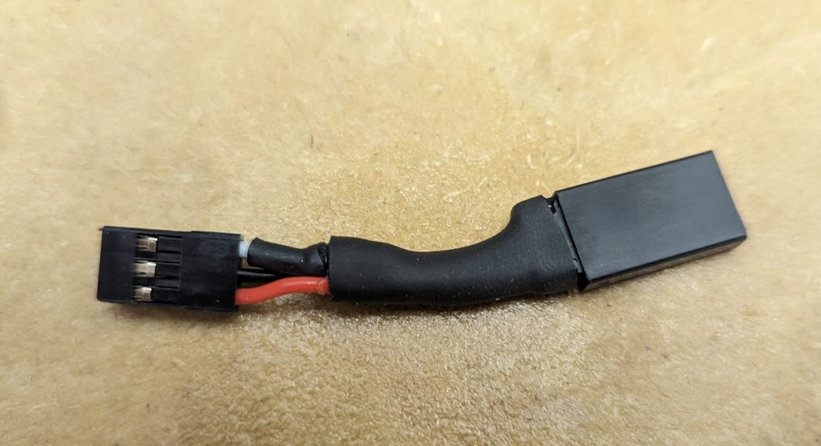
Below are photos of how to make a pigtail to solve the pullup problem without soldering to your board or do anything overly complex.
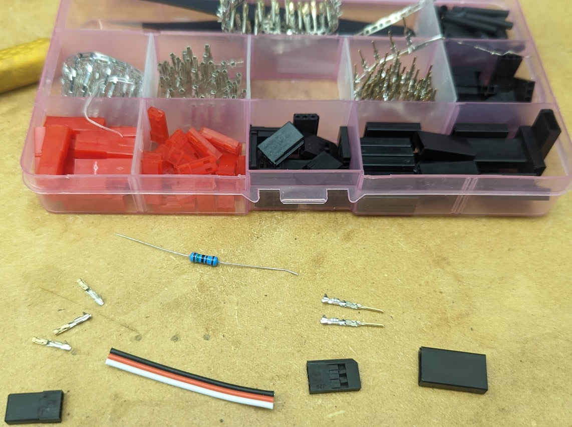
Items required:
1.5k resistors
HiTec Servo Terminal Kit
Crimp Tool
Heat Shrink Tube
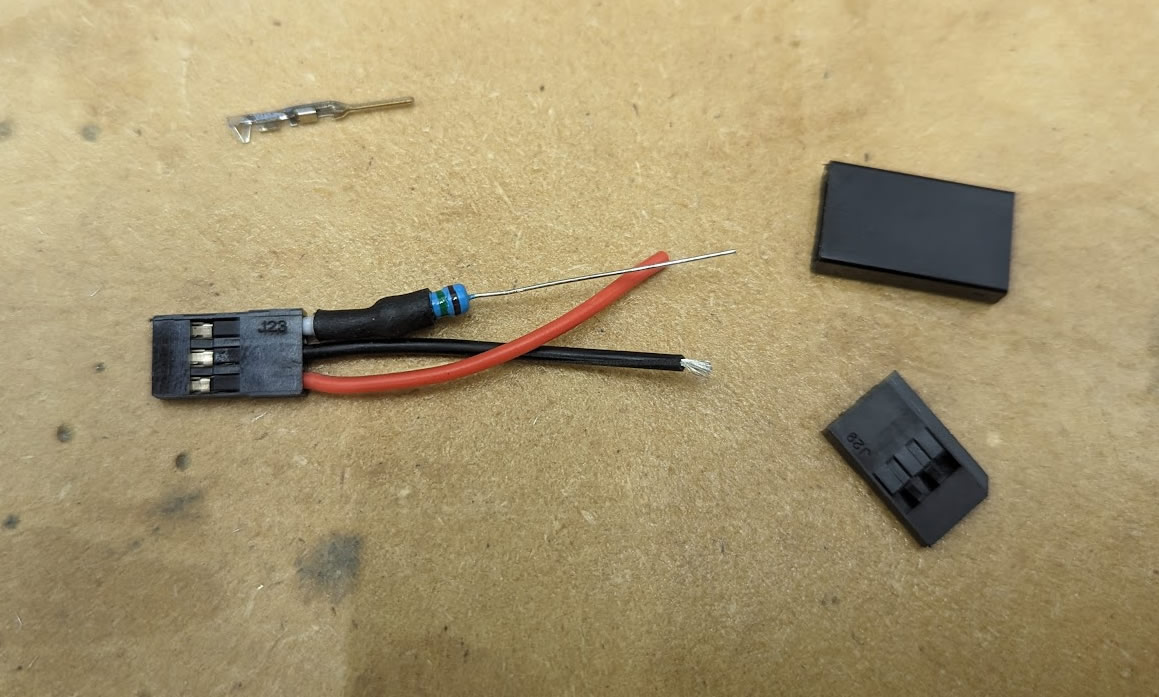
Process in photos:
I make the smallest little white wire possible so it can go into the connector and also be flexible so it can fold over in your case. I then solder the resistor wire (shortened of course) to the white wire.
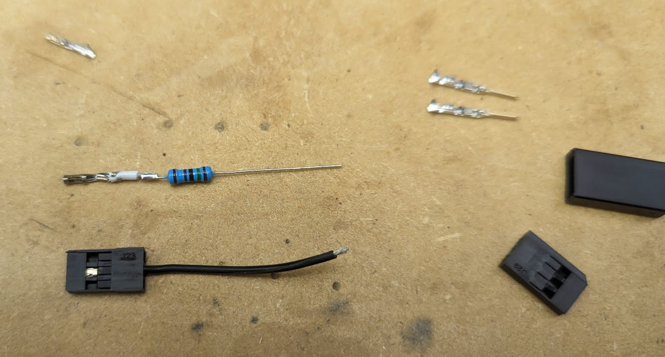
The crimp to the resistor wire was strong, however, i added a dab of solder as reassurance and for a solid connection.

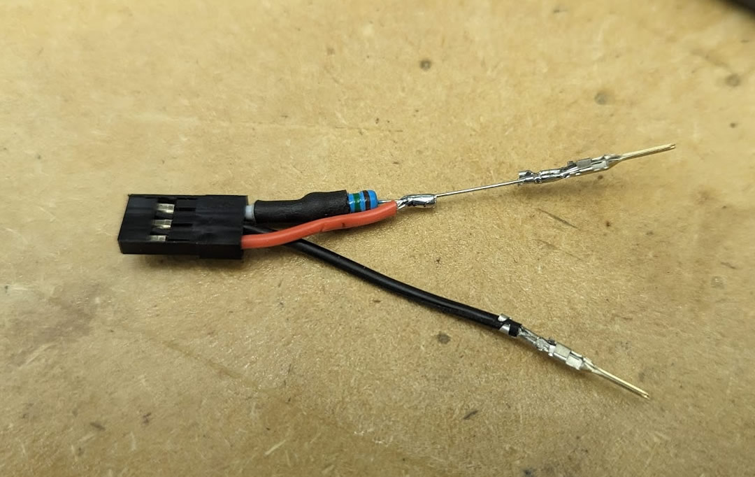


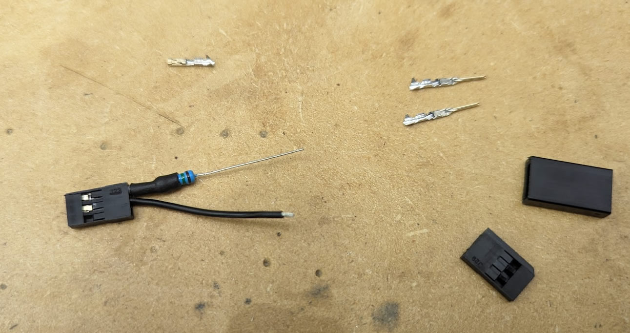
I use heat shrink tube that already has hot melt glue on the inside. It is the best kind IMO unless you need things to remain flexible.