Problem with x not stopping when homing

See solution below.

If M119 returns open/triggered correctly AND your LED on the board comes ON when you trigger an endstop, however, the servo doesn’t stop, you have a pullup issue and should make the pigtail in this thread.

Ok few of the basics…

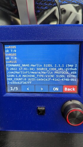
Firmware is right version:
V1CNC_SkrPro_DualLR_2209-2.1.1.zip

It is wired properly according to:

The motion of X is correct per:
X positive (Right arrow) should move Right, X negative should move Left
(so are the Y and Z)

Y2/Z2 and Y/Z stops are both on the same sides so no criss crossing.

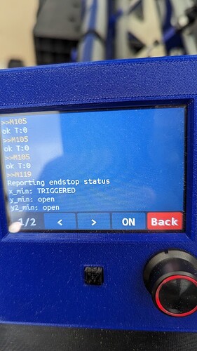
I have tested the end stop via M119. Open when not depressed, and shows TRIGGERED when I close it with my finger.


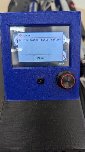
First time around it rammed into the side, ground on the belt a little, then threw this code.

Next time I moved it over and let it hit my finger and held it in and the carriage kept on coming.

Board: SKR Pro v1.2
Screen: TFT35 E3 V3.0.1

Brand new to this. Any ideas would be appreciated.

Oh my build is 4ft x 7ft. Standard 1220mm setup that the firmware should already have preconfigured as max by ryan.

Random note, this morning I actually wound up testing the xmin switch continuity with a meter before installing it. I also tested the line continuity of signal and ground. So I know the switch is good and I know the firmware can see it.

Steps to reproduce press…

  1. Motion
  2. Home
  3. X

I tested Z and it worked just fine.

I don’t have Y belts installed on table yet so I couldn’t test that other than with my finger.

1 Like

Is it reproducible, ie does it happen every time you home the x axis? Or are there instances when it works just fine? Assuming your problem occurs when homing X …

So far every time i have tried it has done that. i have hit the reset button or unplugged the power to quickly stop it. then fresh boot, try again, does the same thing.

i am starting the home anywhere from 1/4 to 1/2 way so 1ft to 2ft away from the stop.

Hmm, that is strange. For whatever reason the software can‘t see the triggered end stop. I understand that you flashed the correct firmware.

We have seen some phenomena with respect to a design flaw in the SKR Pro 1.2 regarding the end stops. There is a hack using a resistor you need to solder onto the board. Unless anyone else jumps in, my advise would be to apply this fix to remove this potential root cause. Will try to find and post the link to the respective thread

https://forum.v1e.com/t/z-axis-homing-1-side-dropping/35155/8

oh man, that would really stink because I’m not about to solder or something to a new board. I assume if it’s a resistor can be soldered in line. I’m hoping not the case though because clearly other people have built this thing and why would I be the one with this issue.

Yeah, I understand your frustration, it is a brand new board and we don‘t want to solder on new boards. It happened to me, I soldered the resistors and since then it has worked flawlessly.

BUT, it may well be a different root cause. Suggest you wait until others jump in as my knowledge may well be limited.

The difference to known cases is that in your case homing always fails.

1 Like

https://amzn.to/3KOTMkp

if it matters, these are the limit switch I used. they were linked from Ryan

Your hardware seems ok, you used a meter to test the end switch. You wired it normally closed, and the software can see it when you manually trigger it, right?

I’m not about to solder or something to a new board.

First you need to verify that the board has the issue requiring resistors. Start by verifying that the X endstop is plugged into the right place on the control board and have verified the endstops with M119.
Unplug everything but the X endstop when you run your test so you know X endstop is wired correctly.

Next start a homing sequence and during the homing sequence, trigger the switch by hand. If the LED on the control board comes on, but the motor does not stop, then you have the SKR Pro board issue. If the LED does not come on, then there is some sort of switch or wiring issue. If it stops when you trigger it by hand but does not stop when fully homing, then you likely have some issue with the placement or triggering of the switch during homing.

It is possible to add a resistor non-destructively (to the control board). You would have to add the resistor as part of the wires connecting to the board. If it turns out you have the SKR Pro board issue, and if you want to try this, post back and I can give you more details.

ground on the belt a little

While the sound is horrible and reminds one of gears grinding, the noise is created by the stepper motor being stalled, and is non-destructive. You are not damaging your belts.

1 Like

yes to all.

I even hot glued the connectors to the board. taped the extension.

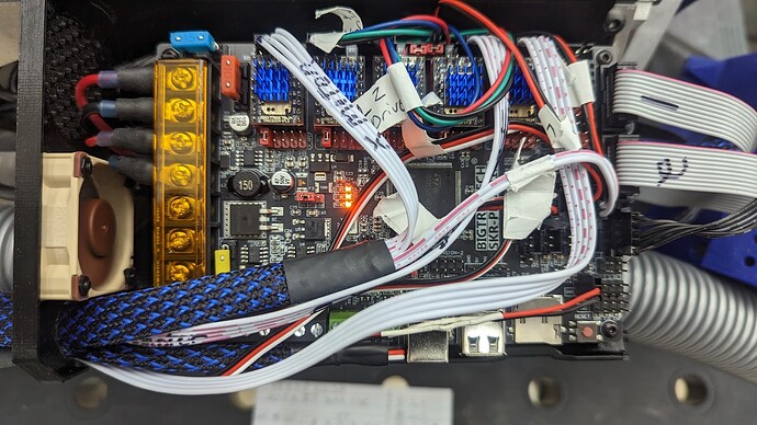
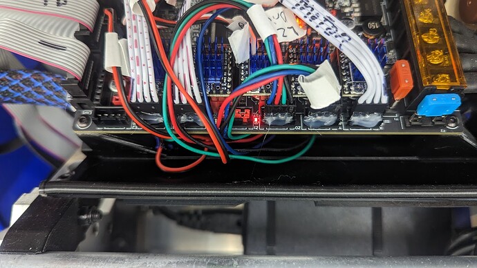
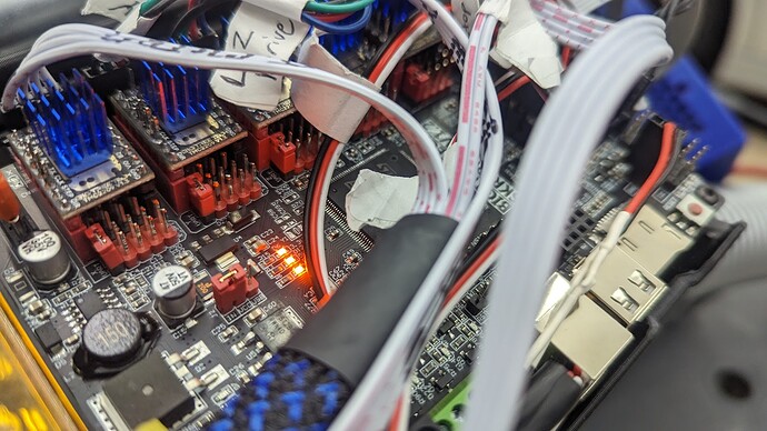
I will have to upload a picture of the board on just in case anyone sees anything.

I have bent the pins on the controller too.

The big indication is that the LED lights up on the X axis endstop on the control board, but the motor does not stop moving. If this is what is going on, it is a very strong indication of the problem we’ve seen on the forum with a few SKR Pro boards. The fix is either a pullup resistor connecting the signal pin to the VCC pin, or to disconnect the LED.

The resistor connection between the signal pin and VCC can be done by modifying the wiring. You don’t have to solder the resistors to the bottom of the board. If you want specifics on how you might modify the wiring, let me know.

1 Like

@robertbu that is funny you say that check out this video. the LED lights up when i hit the endstop but the X doesn’t stop. lucky me… a few skr pro boards.

i suck at circuit boards. wiring cool, soldering to a board nope. when you say “disconnect the LED” can you please tell me how. I am assuming with a soldering iron?

i like the idea of modifying the wiring. i would definitely like specifics. i actually have 3 pin connectors in the stop holes, i just removed the white wire from the plug.

i am going to guess… replacing the board wont necessarily solve my issue correct. seems like it is luck of the draw. i am still within the return period.

as promised a few more photos proving instructions were followed.

i have a fan wired in that’s about the only non stock thing. from what i read on here though i can put it on the two pins in the photo.


i am going to guess… replacing the board wont necessarily solve my issue correct. seems like it is luck of the draw. i am still within the return period.

On the forum, we saw several boards with this problem in a short period of time. After that, only an occasional topic that turned out to be this issue. My theory is there is a bad batch of boards, and that occasionally one of those boards ends up on an MPCNC.

The problem is related to a design issue with the SKR Pro. The microprocessor on the SKR Pro is reading the signal pin of the endstop to determine if it is HIGH or LOW. The LED uses the signal pin as power. This results in a lower HIGH voltage. With an out-of-spec resistor or LED, the voltage never gets to the point where the microprocessor sees the pin as HIGH. Adding a resistor or disabling the LED results in a higher HIGH voltage, solving the problem.

It is highly likely that, if you return your board for a refund and purchased a board from another place, you would not have the issue. If my theory of a bad batch is correct, getting a replacement board from the same supplier might result in just getting another board from the bad batch.

when you say “disconnect the LED” can you please tell me how.

Anything that disconnects the LED will work. Taking a sharp knife and cutting the traces to the LED will work. Unsoldering the LED will work. From personal experience, I would advise against trying to pull the LED off the board. For me (not on a SKR Pro), this resulted in pulling the traces off the board. Note that while the suggestion of disconnecting the LED has been made on the forum a number of times, I don’t remember anyone posting back that this is how they solved their problem. Everyone seems to use the resistor solution.

For the resistor, a value of 1.5K has been suggested, and resistors of values around 1.5K have solved the problem. It needs to go from the signal pin of the endstop plug to the VCC pin. In your picture, you have SGX listed. The ‘X’ pin is VCC…3.3V. Since you already have a third plug, it is just a matter of splicing into the signal wire to span the two. Personally, I’d carefully peel back a bit of the insulation on the signal pin (without cutting the conductor), wrapping the resistor lead around the conductor, and soldering it (probably optional). In this wiring, you do want to be careful not to short the VCC pin to the G pin.
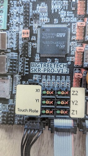
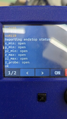
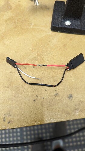
It would almost be better to make a little adapter pigtail that has male and female ends and adds the resistor in the pigtail itelf.

Then a person with a suspect board could test by just putting the pigtail in line, and if that fixes the problem then it could be left in place.

1 Like

what wattage resistor? they make 1.5k in 1/4 all the way up to 2 watts.

so basically I am going solder in the resistor to the jst, put the just back in the plug in the vcc position, then peel back some insulation on the S and solder on the other side of the resistor. does it matter which way the resistor faces?

@robertbu pls see above question plus double check this photo. I am making a pig tail. once I get the resistor you can see where it wires in. is that right? two exposed wires are connected with the resistor.

this is just to test then I will make it pretty