Whenever I have ideas, I tend to want to create a fully functioning instance on my own before revealing it to the community here. However, this time I think the idea is not only potentially quite beneficial to those with their LR3 riding on superstrut, but also potentially stands to benefit from input/collaboration.
Here’s my idea: Instead of having my LR3’s long belt (usually Y, although I have my axes swapped) riding up above the table, I could design and install both a quick-release belt tensioning system for inside the superstrut, and also design a new Y motor mount replacement that would move the Y motor to make use of the protected, hidden belt in the new location.
Benefits include:
Belt is protected from having tools, materials, and hands catching on it, dragging it, pulling it, etc.
For those who, like me, due to room and LR3 orientation, do their material loading and unloading via the long side of the table, the belt would not be in the way.
Belt gains great protection from dust, debri, potential sources of cut or burn, etc.
Coolness factor x10.
I welcome your input and collaboration. I’m pretty intent on pursuing it!
I jokingly considered labelling it the LOW-LowRider v3. LOL.
UPDATE, Saturday, Feb.11, 2023:
This is working flawlessly over the course of many, many cut jobs. I’m super super pleased. It’s exactly what I was hoping for!
I will be making the files for this available publicly. I had given early access to my Patreon supporters. However, I later made an administrative decision to delete my Patreon account.
Starting sometime soon, the details and files will be available for download from my Printables page here.
Please consider a couple of things:
Even if you are not running your LR3 on superstrut metal, you could still do this, by simply remixing how the new tensioners attach underneath whatever table edge or “lip” you are wanting to hide the long belt under.
Even if your LR3 is running farther away from your table edge than mine is, you can still do this by simply increasing the length of the printable “standoff” file, via a remix.
This would ve better suited to a LR2, I think, which already had the belt below table-top height. In fact, it’s probably not even a large deviation from the existing LR2 build, just changing the roller offsets from the Y motors.
To me, the LR3 being entirely above table is one of its big advantages, and a primary reason to go to this design from the previous LR2. also, having the table long edge against the wall made it more shop space friendly to me. As soon as the belt moves inside the strut, that’s no longer possible.
If you have a strut build, the inside of the build is extra room for something. Might as well be a belt. I am not sure how you get the Y way down there though. My brain just can’t see it. But it sounds neat.
What else could you use that space for? Clamps? Power cords? LEDs? Vac hose? Extra pencils? Bit storage?
@SupraGuy — I completely understand. This mod would surely not be for everyone. For me, one of the things about LR2 that I really liked, compared to LR3, is that the belt was below the table. Since my room space limits me to loading and unloading material only on the long side, I’m always having to detach and reattach the belt (thankfully not hard to do) and “otherwise” deal with the belt being in the way for many other tasks I do on the table. I’m seldom bothered by the far side belt (where my EMT conduit is that the far side rolls on). If I got this mod done only on my near side it would be enough for me. I’m spoiled I guess. I know the continual removal of the belt and reattaching it not hard. I’d just like to get to where that component of the system was hidden away, out of the way.
So what you need here is something that extends the Y axis drive past and below the table edge. I can picture a solution, but I’m less sure about appropriate materials to make it with. Its a pretty long moment arm to depend on printed plastic.
Would love to see what you come up with. Ideally I could change the way i have my table and free up some space in the shed. (would be great to load long ways)
Can’t you just modify the drive the guy with the the idiot’s tale made? His belts are driven on the bottom, if you lower them a bit it should be doable, right?
Alas, I don’t think that’s an option, at least not in and of itself. His belts are still on top of the table, which in my case would mean, on top of my superstrut. The opening for the superstrut is facing outward to the side, and so the placement I’m pondering is to keep the stepper motor in the same orientation, but move it outward and downward. It may or may not be a “feasible” thing, but I’m just exploring it in the hope I can find an approach that not too “un-elegant.”
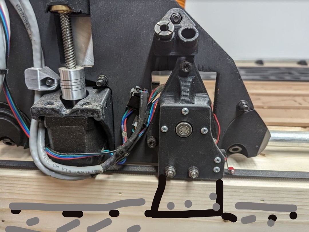
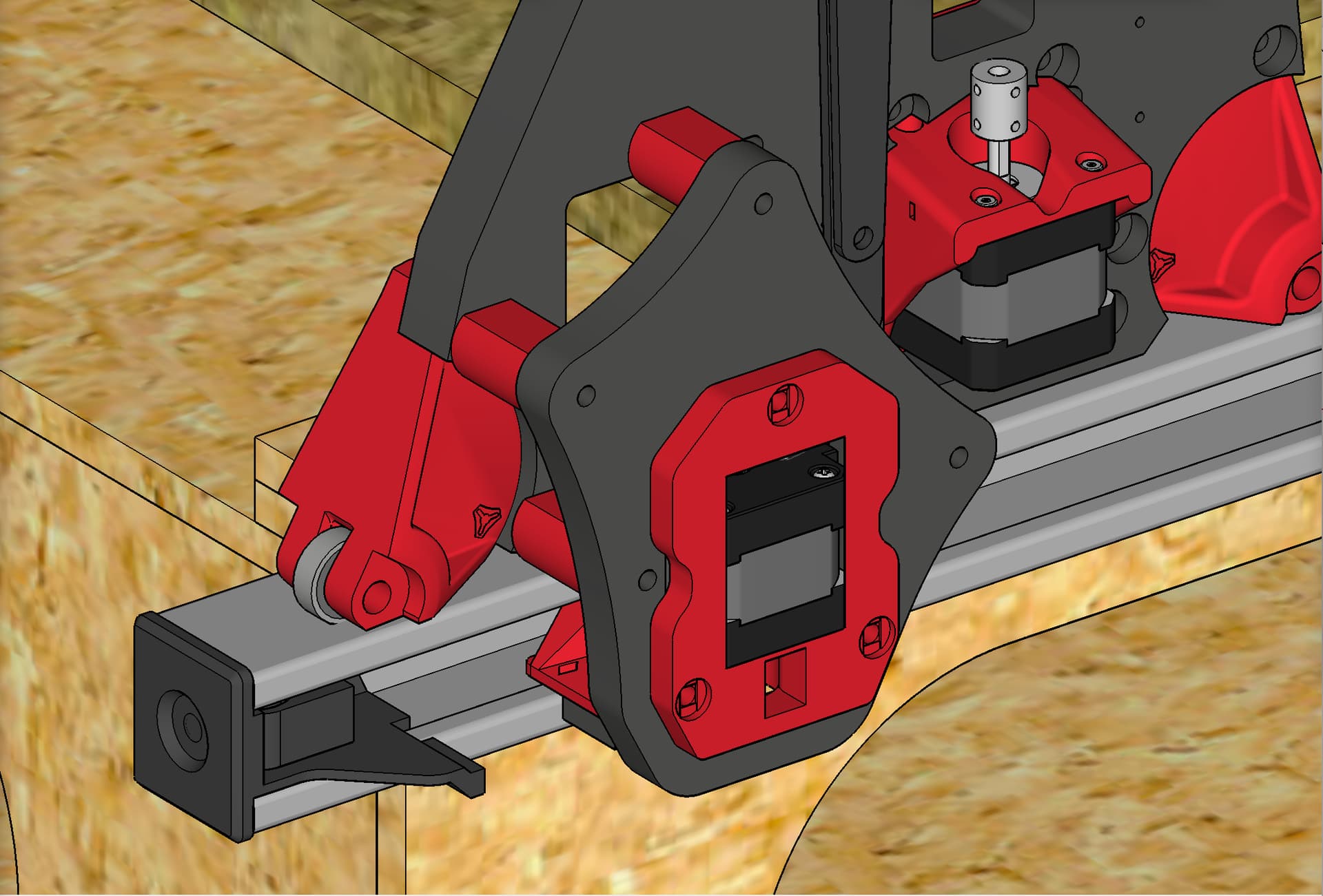
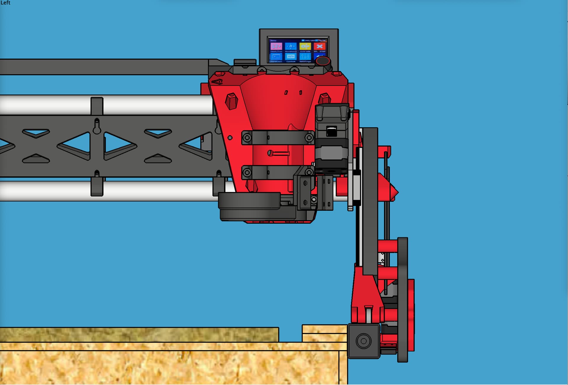
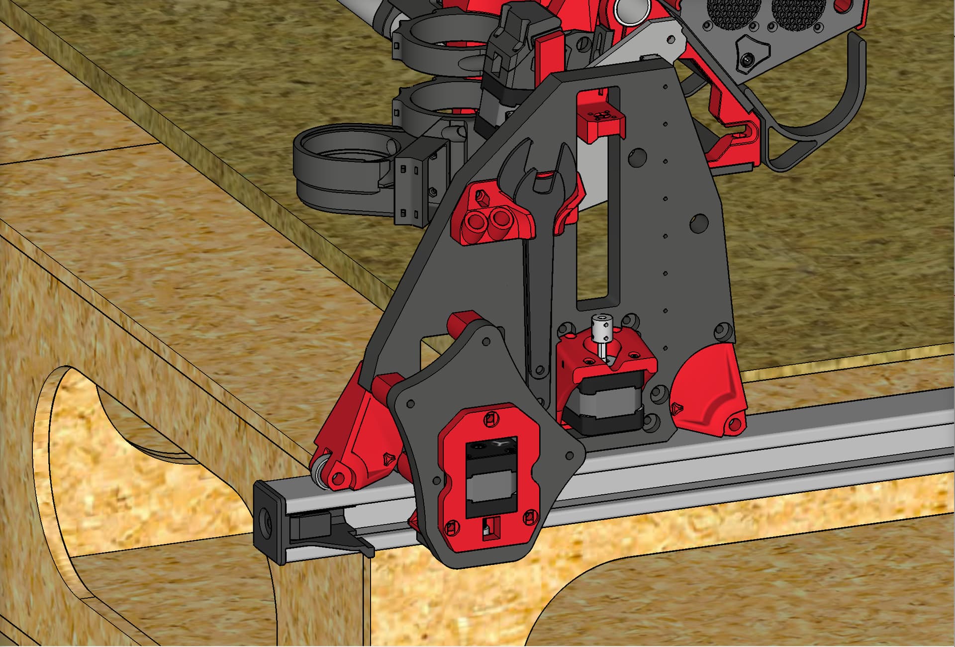
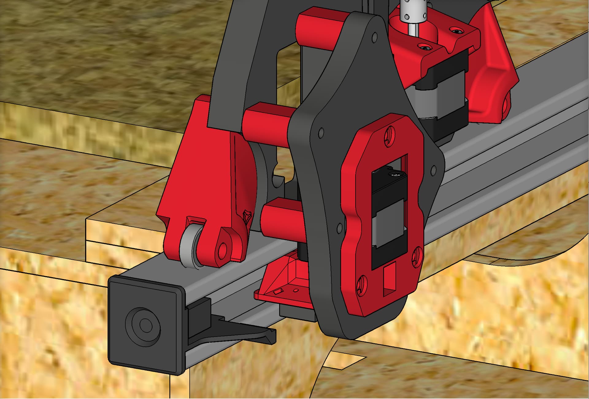
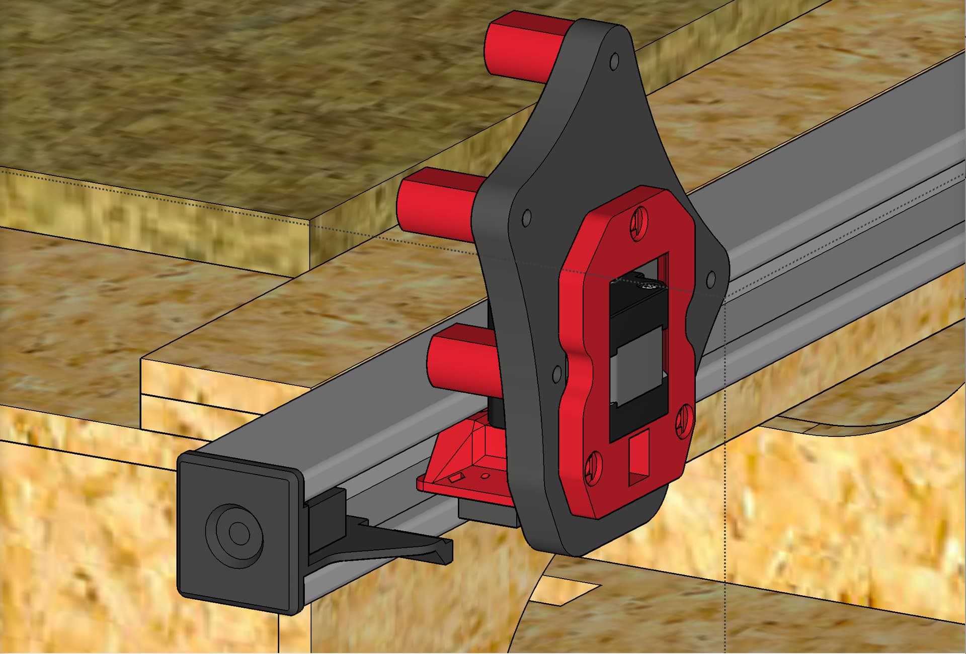
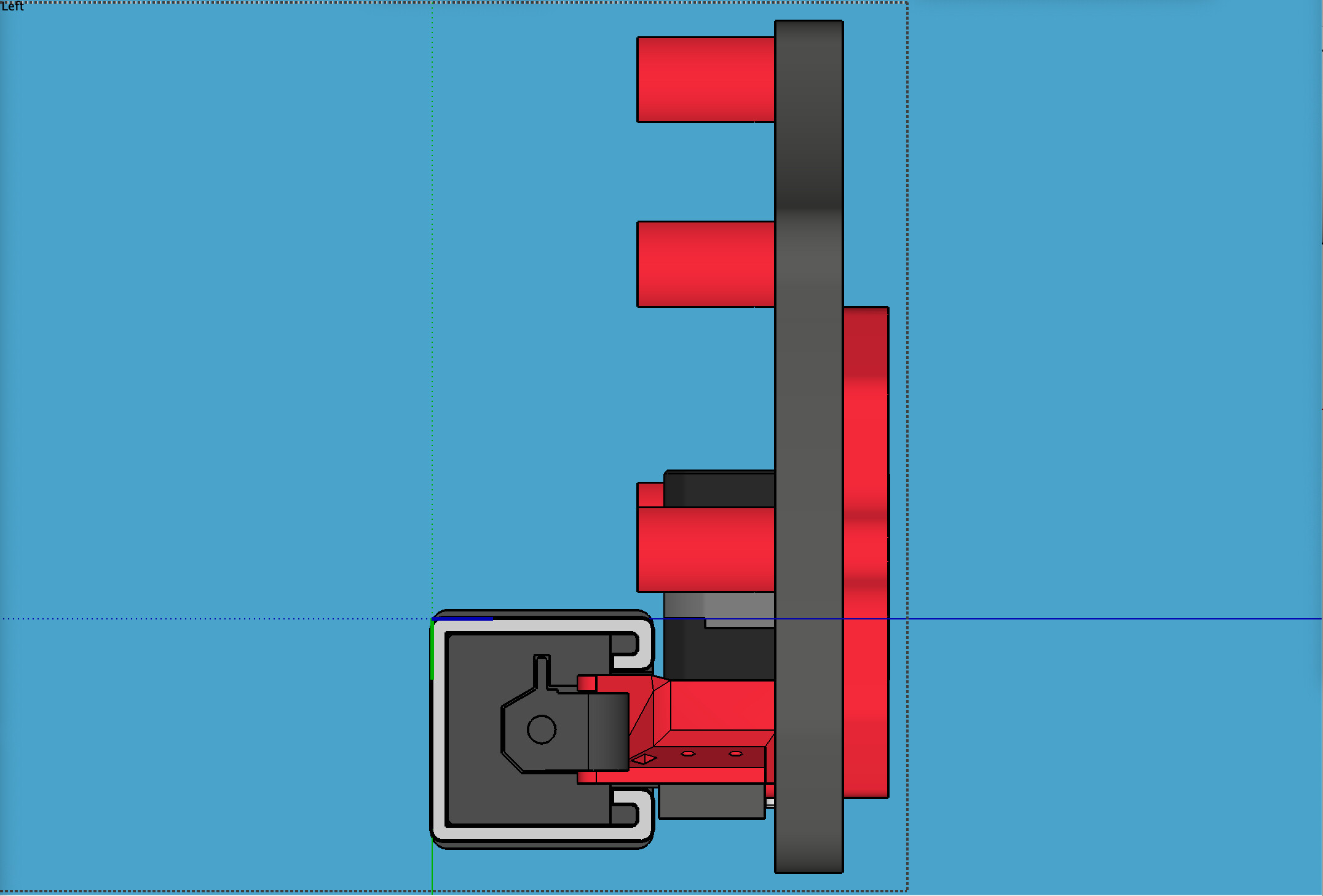
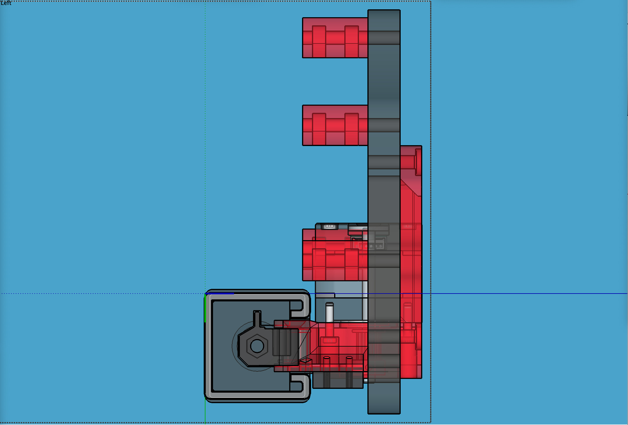
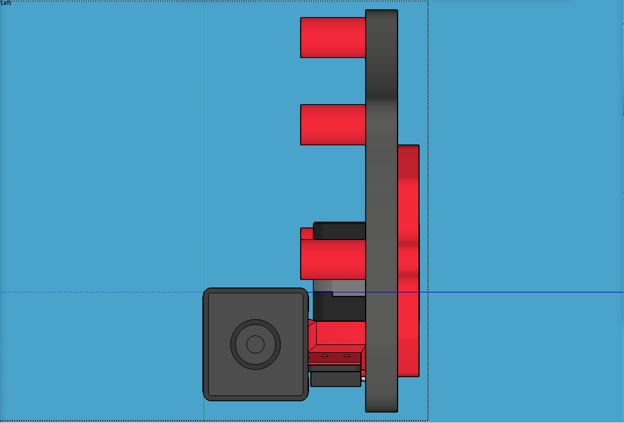
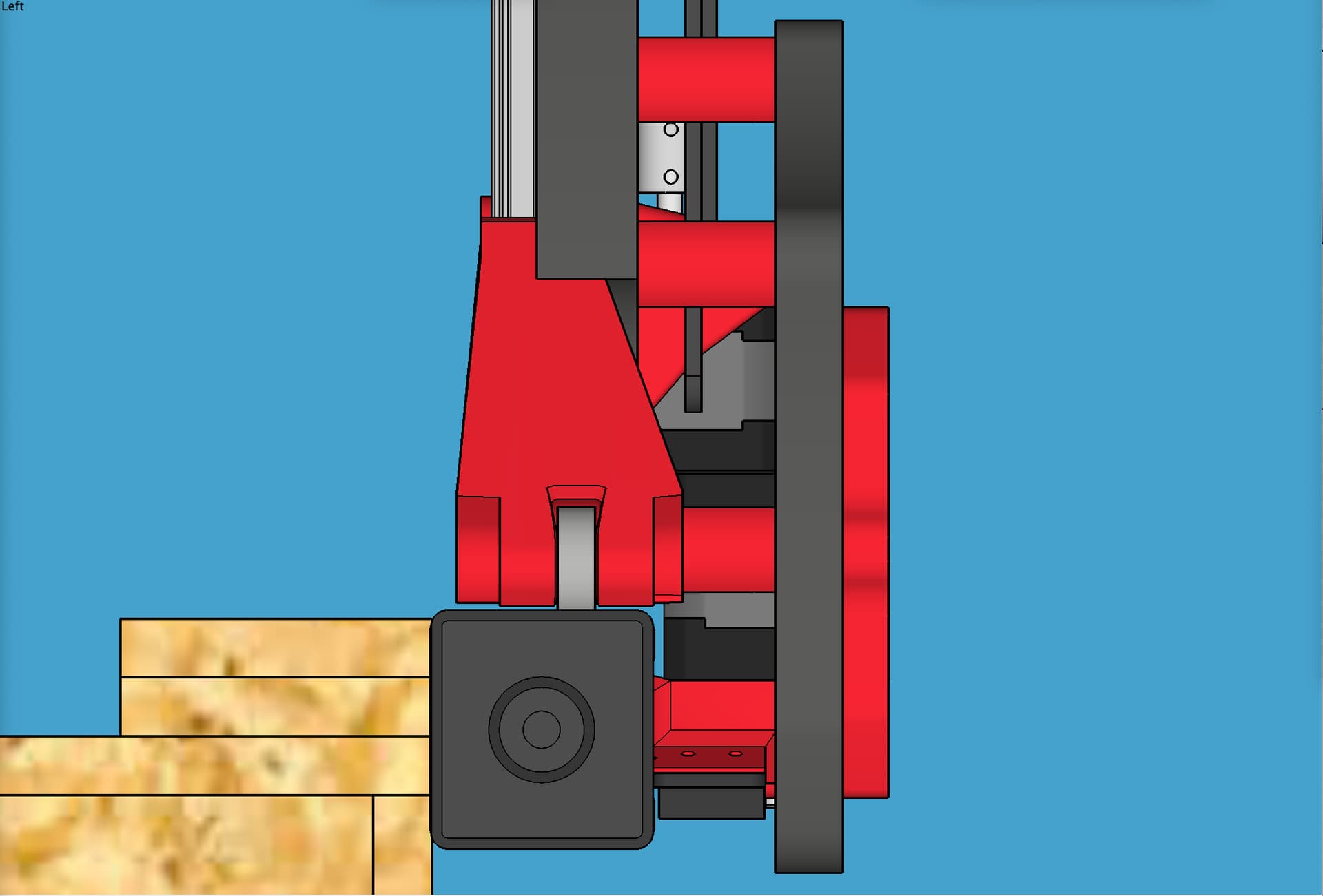
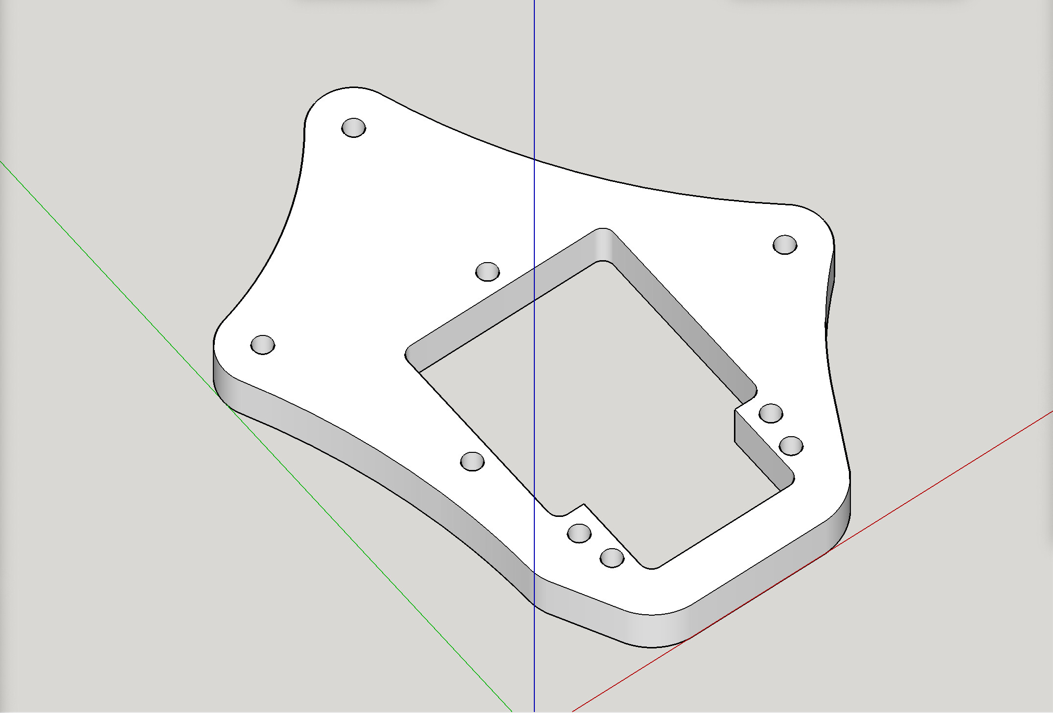
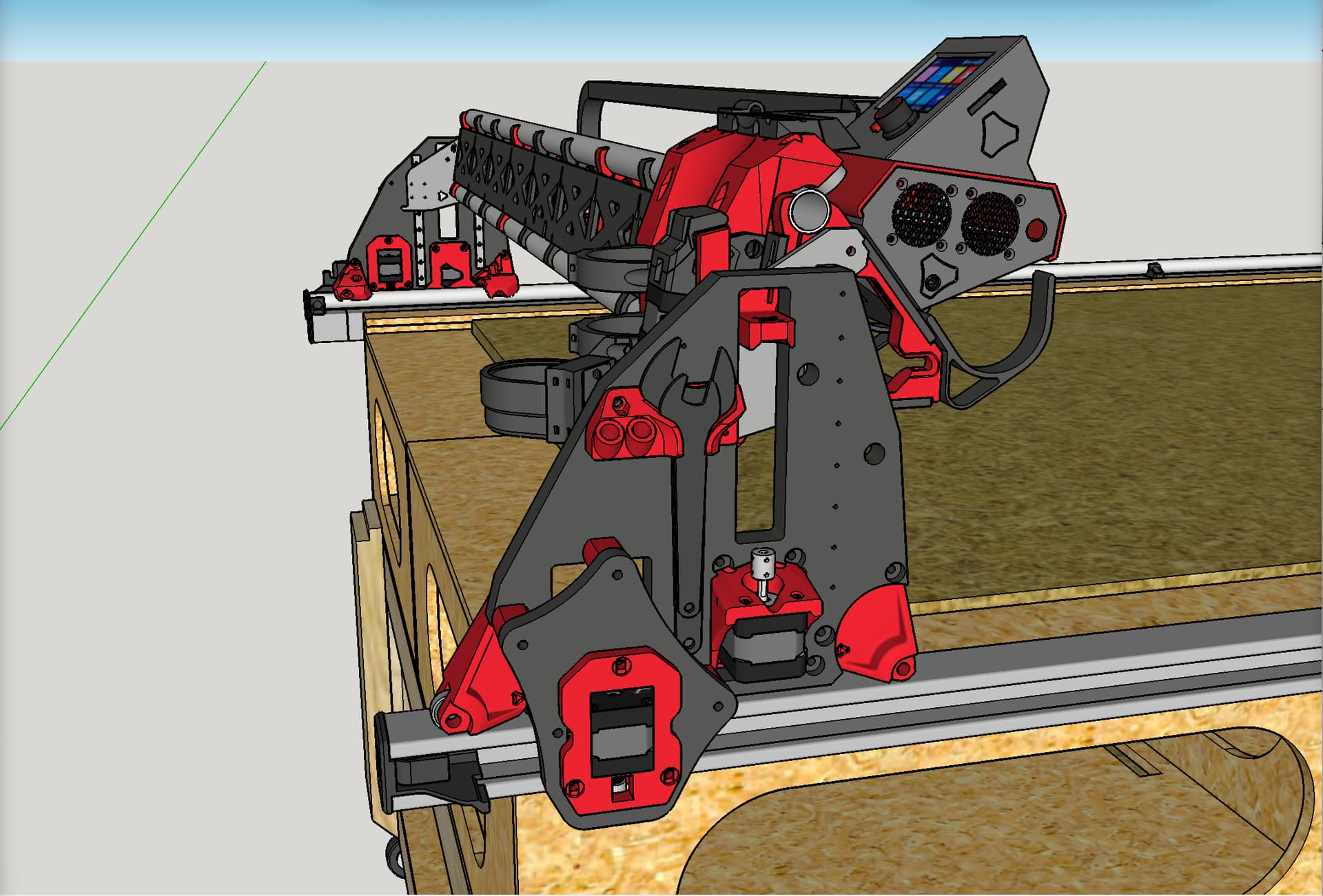
OK, so here is what I am planning at this point. This involves a cut MDF plate (a secondary Y plate) that is spaced off from, yet also attached to, an existing, stock YZ plate, using spacers (or perhaps coupler nuts), and to that secondary Y plate, a custom new remix of the original LR3 Y mount will be inserted, positioning both the endstop switch and the long belt in a new position, with the belt being hidden and protected inside the super strut.
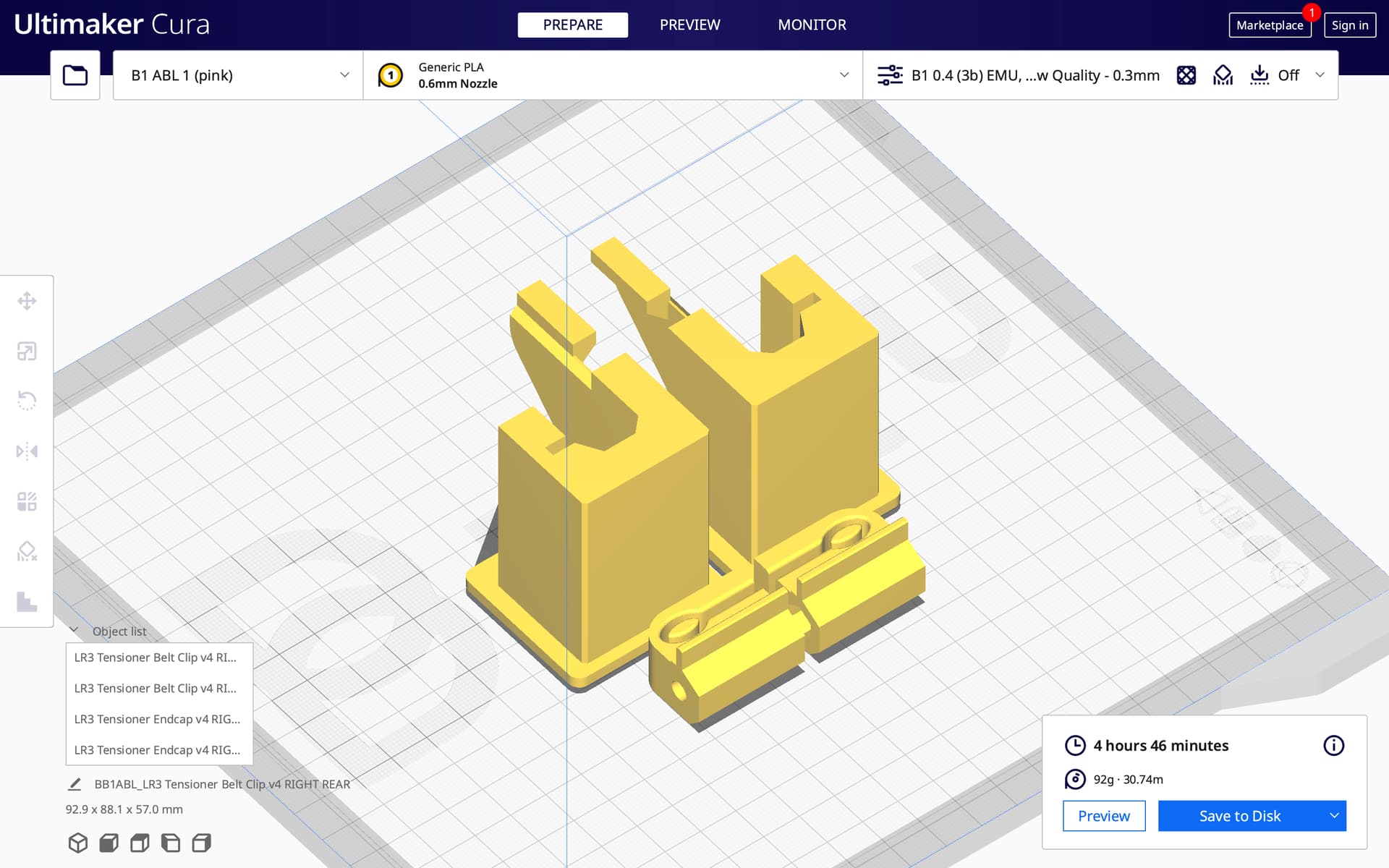
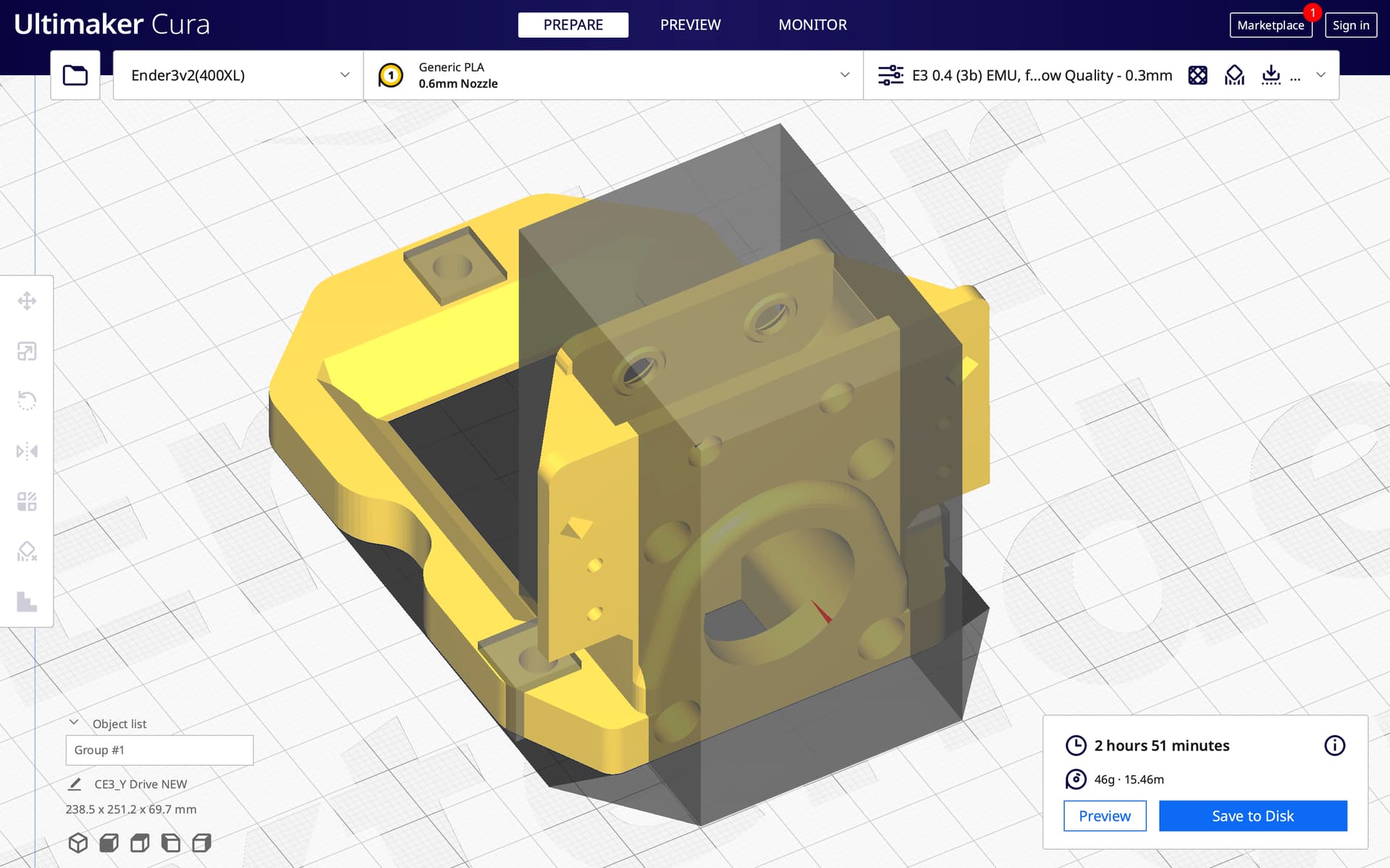
In my desire to keep the placement tight, due to a necessity, the new Y mount does need a little bit of supports during printing. I am using support blockers to minimize the amount of supports. It’s adding only a very few minutes extra print time.
Four of the existing screw holes on the stock YZ plate will be used as anchor points to attach the new secondary plate.
Curious to see how this turns out. Thanks for sharing your thinking and journey @DougJoseph.
Is it worth using this opportunity to also reduce impact of belt slack? Would be especially helpful for longer table lengths. Previously seen one piece of belt glued to a substrate, then another belt piece fastened such that it mostly meshes with the fixed belt, except for the small portion of idler tensioned belt that wraps around teethed pulley driven by (typically) y-axis steppers?
Looks like some folks (@claytonisbob, @tgm022861, maybe others?) experimented with using a glued/adhered ‘fixed belt’ for the tensioned belt to be meshed with. Goal being to reduce effect of belt slack, especially for longer belt runs. No idea what difference this’ll make to performance? Was considering positioning belt teeth facing/oriented same as today, somehow housing/protecting using cheap shallow L or C channel profiles available from big box store, but honestly haven’t spent much time thinking through this one.
My machine has one 6’ belt (X-axis) and two 10’ belts (Y-axis).
If I move my spindle to the midpoint of the gantry I have even belt tension on both sides of the spindle. However, when I move the spindle to 1/4 the span of the gantry the tension on the longer belt length decreases while the tension on the shorter belt length increases.
The effect is more dramatic for moving the gantry along the Y-axis.
By capturing the belt in a rail the tension remains even across the full length.
My rail is not a length of belt adhered to something. The meshed profiles are not precise enough. My rail is like the teeth of a belt pulley arranged in a linear fashion for a precise fit.
So, the images / plan I showed above, are for the “near side” long belt, (Y for most LR3’s), but I’m also looking into a plan for the far side as well (the side with the conduit guide).
I just took a look at my far side arrangement, and it’s going to be (arguably) easier on that side, or at least more direct. A modified YZ plate and modified mount could do it, strongly, with no need of a secondary plate like on the near side.
I‘d fear that the whole construction was going to be ripped apart when one driver fails or skeps are skipped and the gantry twists. Now it does not matter much, but if the parts are constrained, they could snap, couldn‘t they?
I should mention, I did not have any 1/2" MDF, only some 3/4", and so I decided to make the secondary Y plate out of 1/2" plywood (the hard strong stuff).