I love the idea as it means the Y steppers and belts are not removed from the rail.
What we do need is a quick-release from the Y-Z plate and a way to make sure the Y steppers don’t fall off the rail when they are disconnected from the Y-Z plate.
You do fantastic designs; I hope you can make this work!! I want to put it on my LR3, which already has a set of rails with your parts. One of the concerns I have is ensuring the Y belts/stops are not changed much when I remove the machine from the work surface.
My current concept for its quick disconnect is perhaps not what you are thinking of. This current plan would have a secondary Y plate with the Y drive mount and it would be rigidly attached to the main YZ plate. To disconnect, which I would very seldom need to do, loosen the tensioner screw, pop the belt out of the tensioner (near end, Y-min, presumably) and slide the gantry out by sliding the new Y drive out of the end of the superstrut. That’s a little more involved than the current plan, but I would prefer it. With the belt hidden away and protected, I would almost never need to disconnect it.
Well, I’ll be moving the rails fore and aft on the sides of the worktable and would like them to always be keyed to the stop blocks. I have plans to put alignment pins into the sides of the worktable to resister the rails when I do change their position.
Some additional bits of info on this as I’ve worked through it.
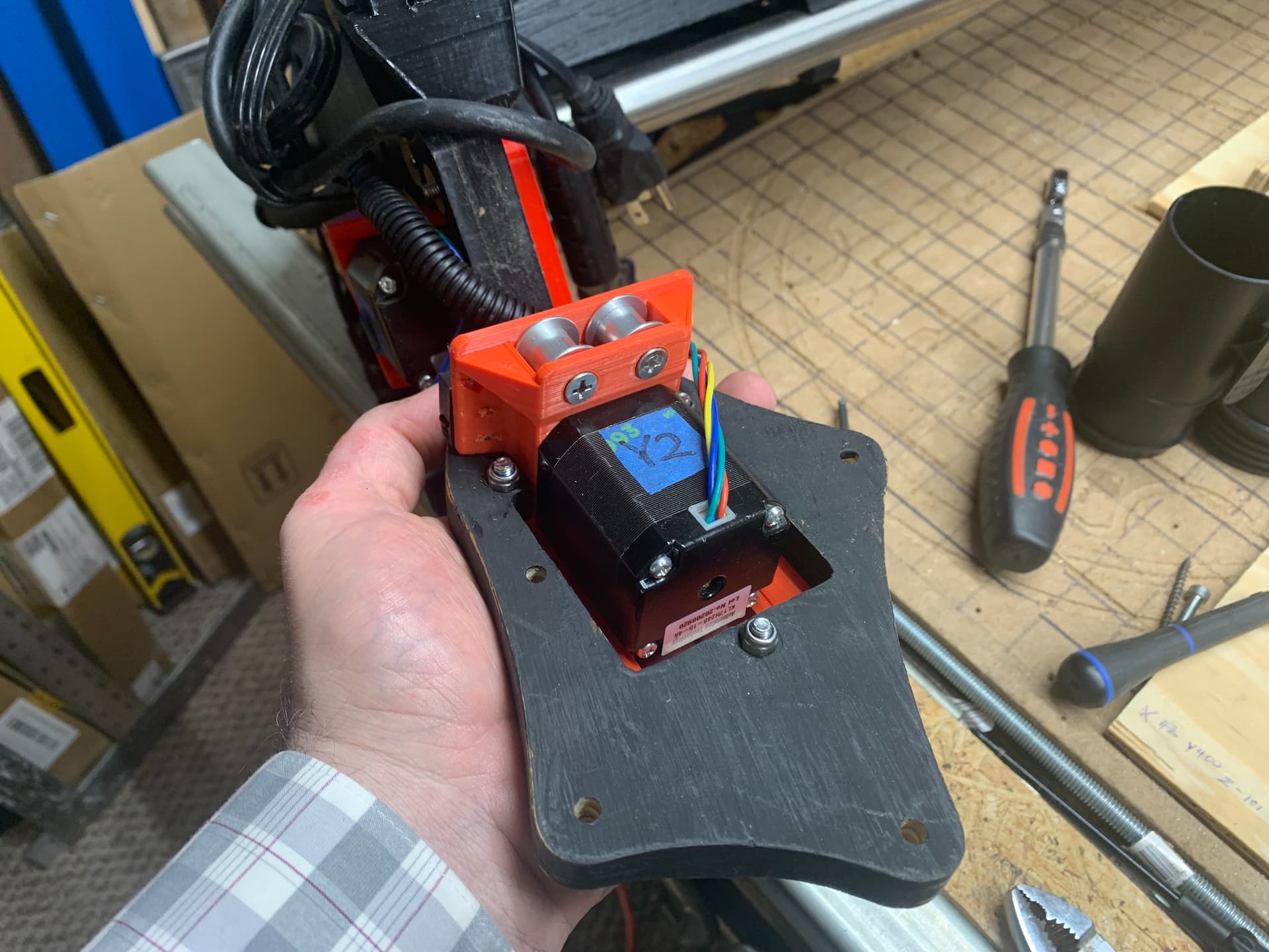
New Y Drive orientation - direction change
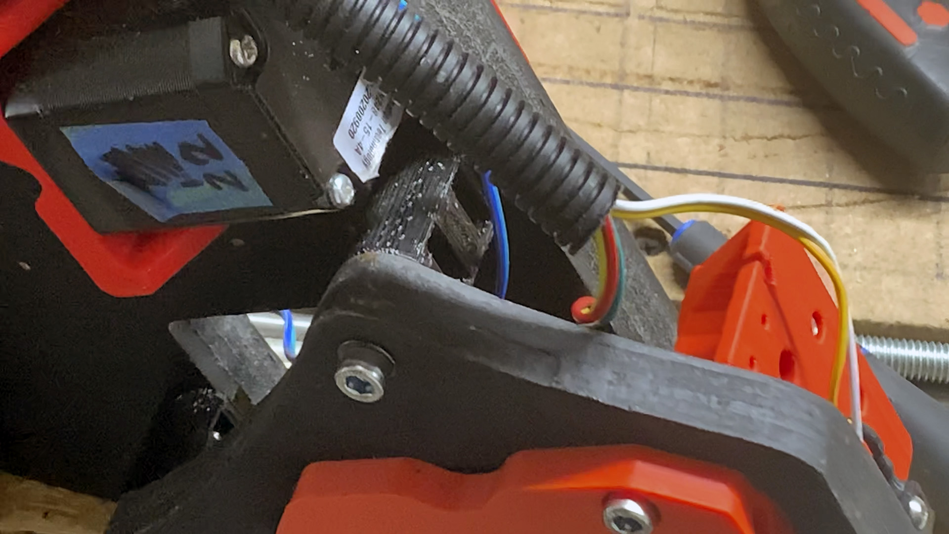
Since the Y motor gets rotated so it’s facing the opposite direction, its wiring had to be reversed where it connects to the mainboard (in my case an SKR Pro 1.2), or else it would be moving in the wrong direction. Easy change.
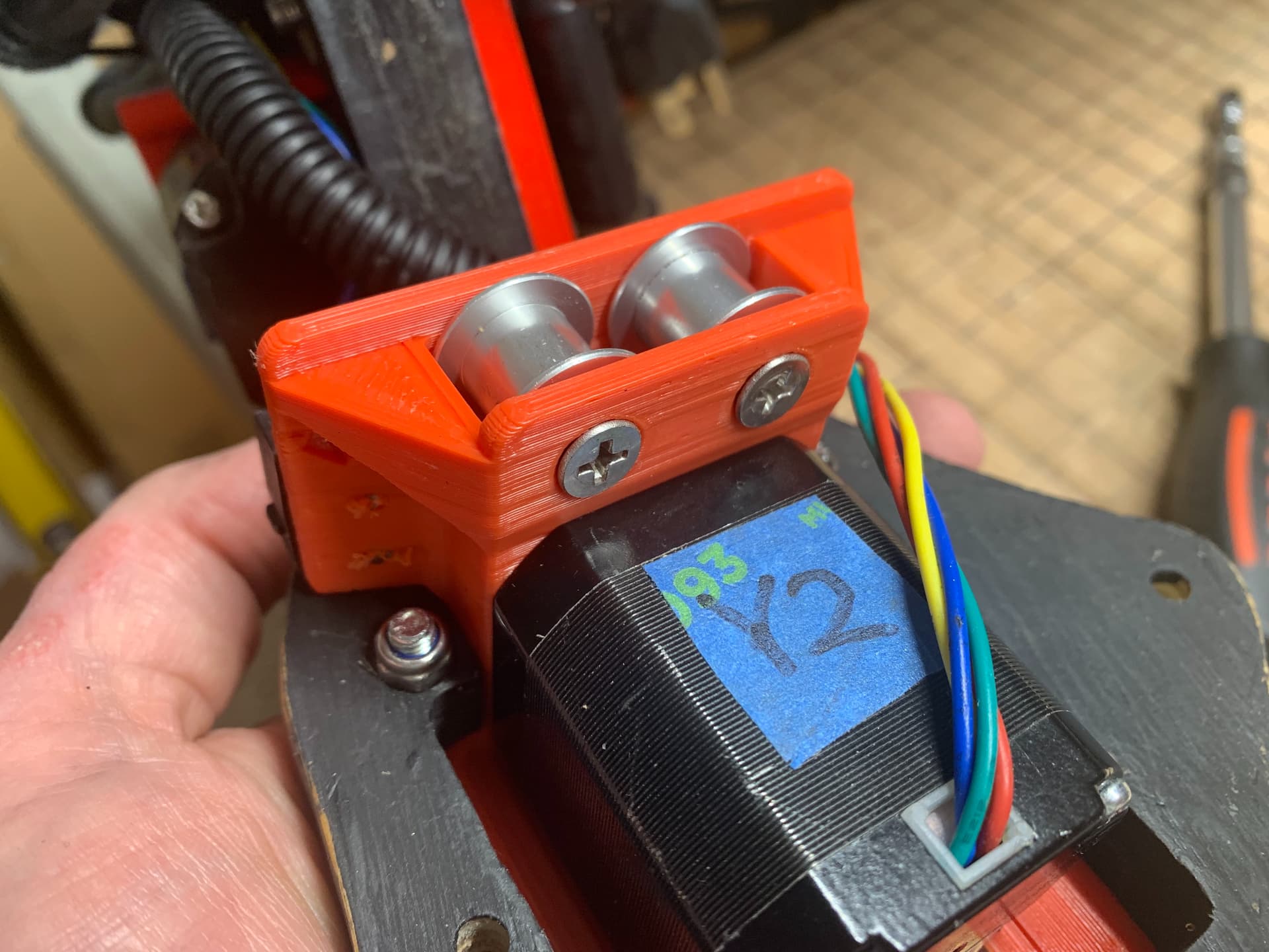
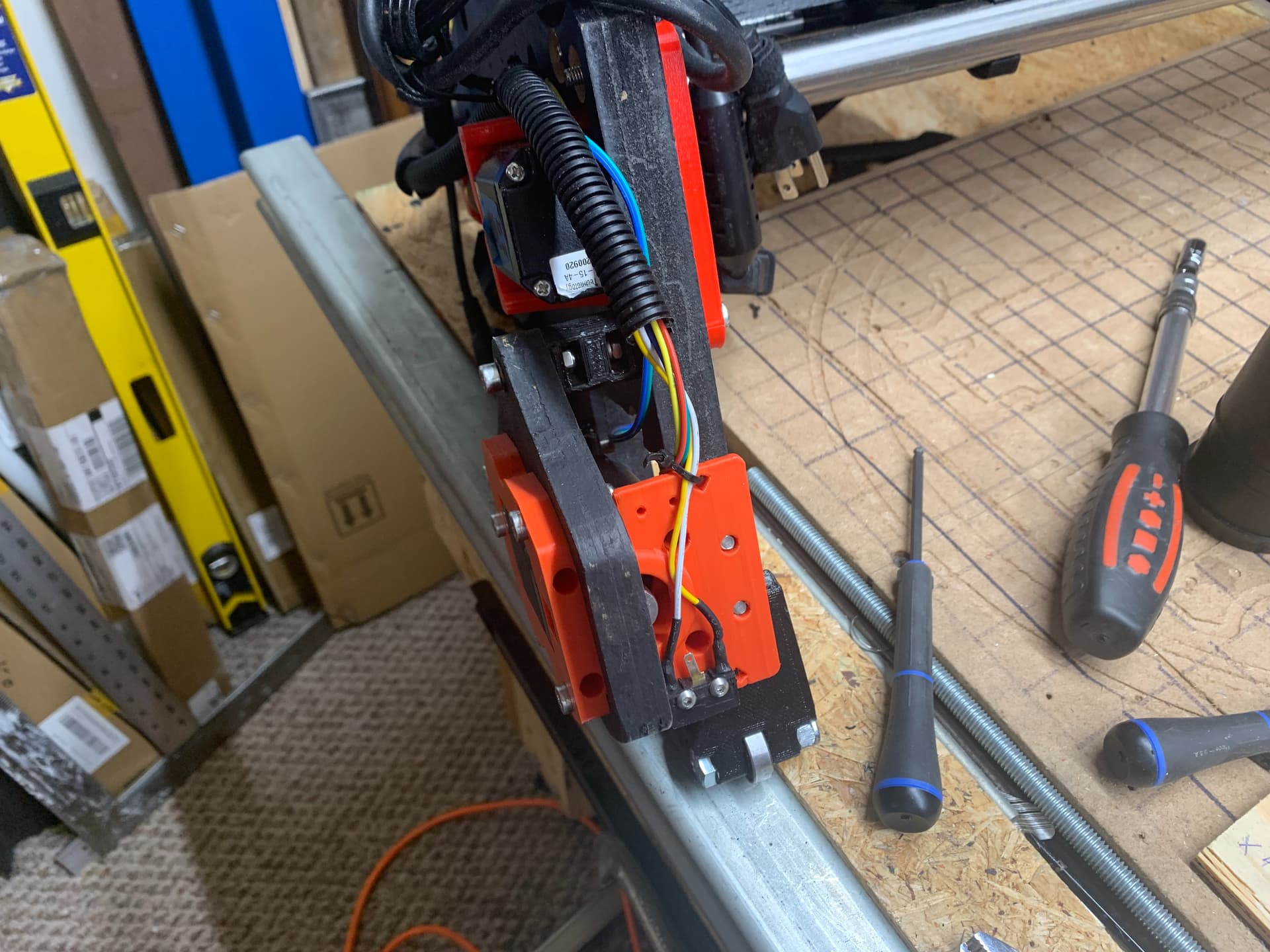
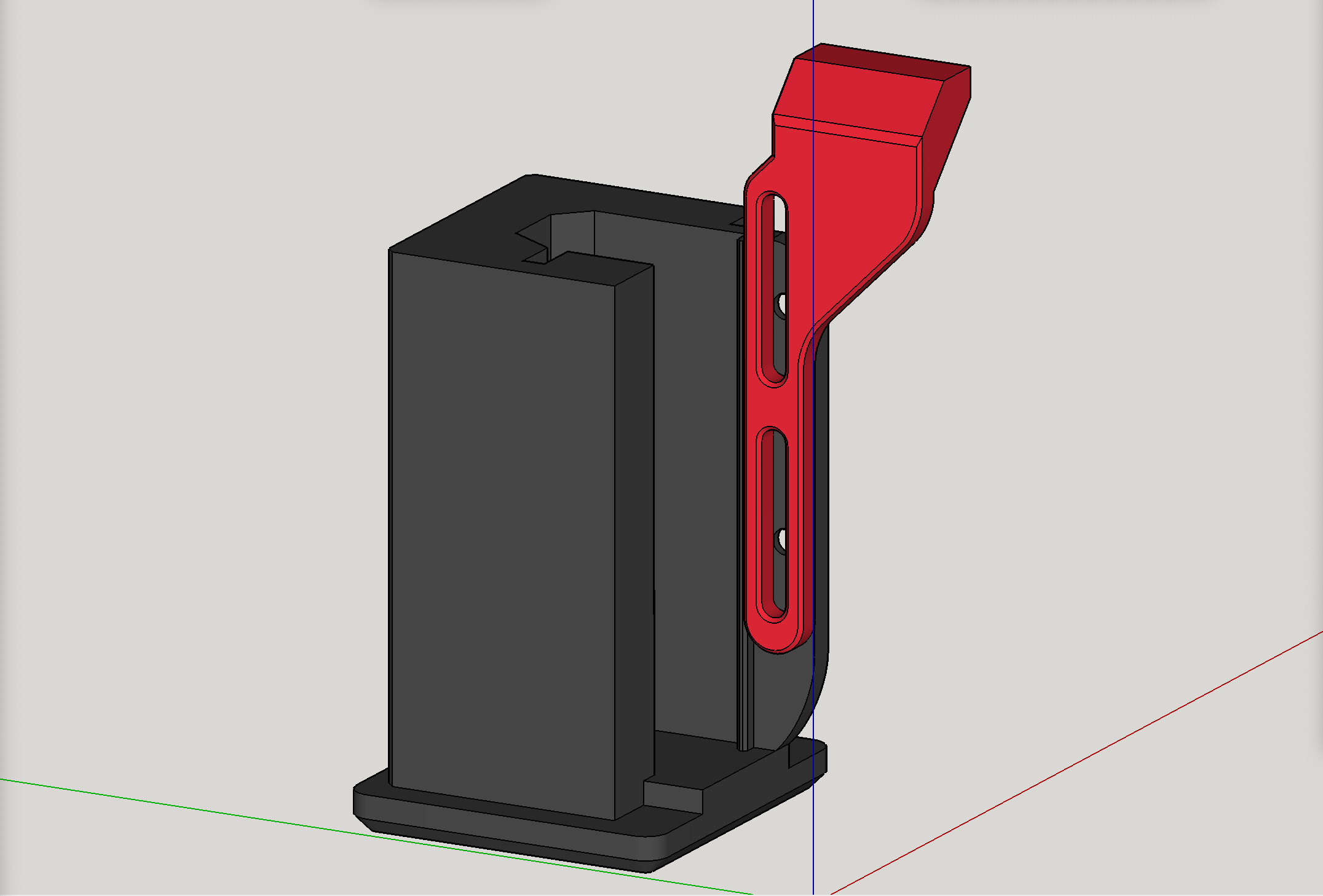
New Y Drive Motor Mount
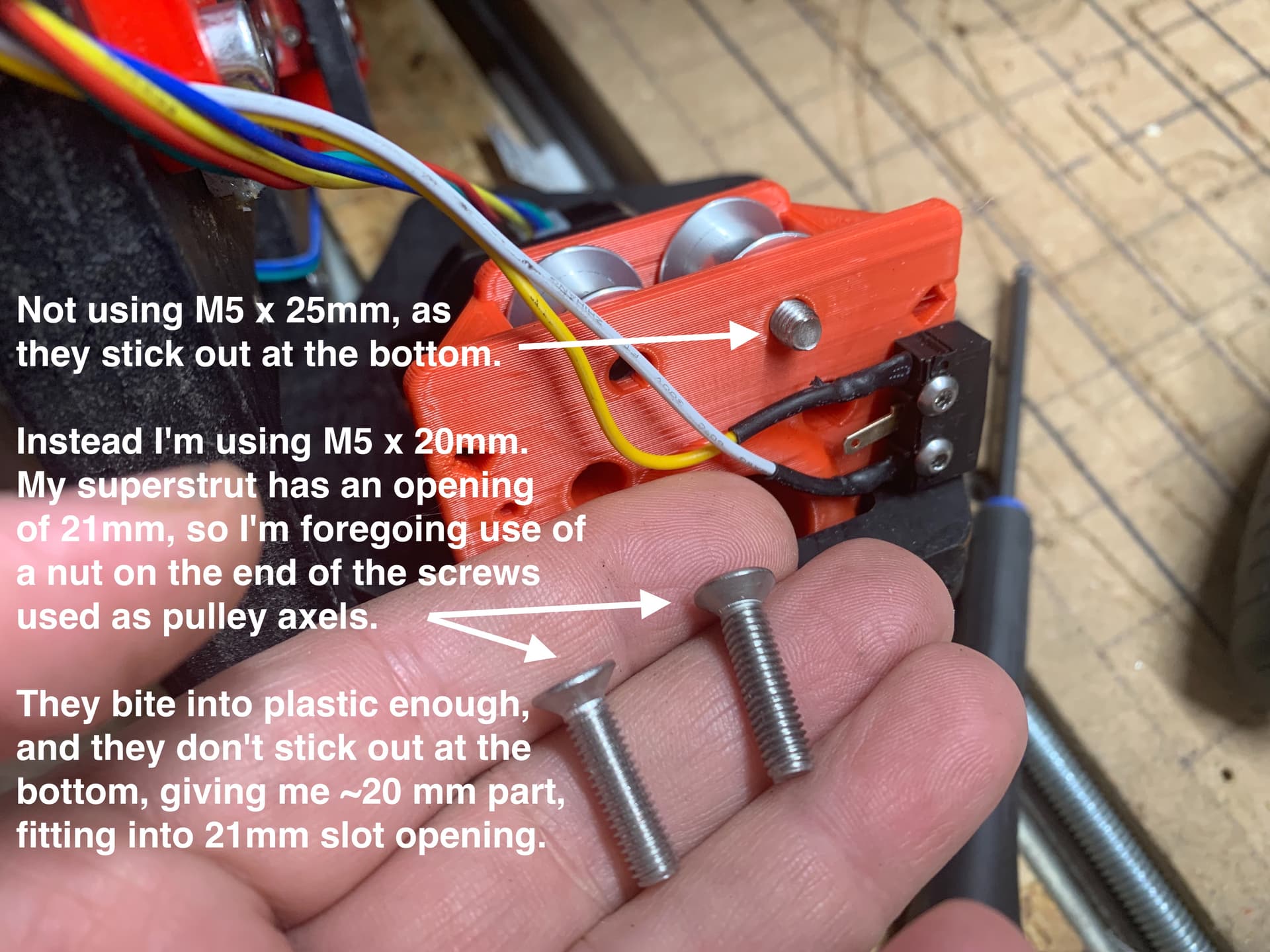
This image with labels, shows info on my new remix of the Y drive motor mount, revised so its “business end” is only approximately 20 mm tall, including any protruding hardware, which is crucial because my superstrut’s slot opening is only 21 mm tall.
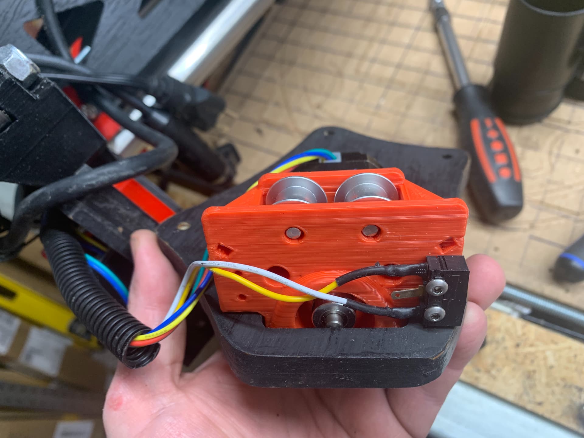
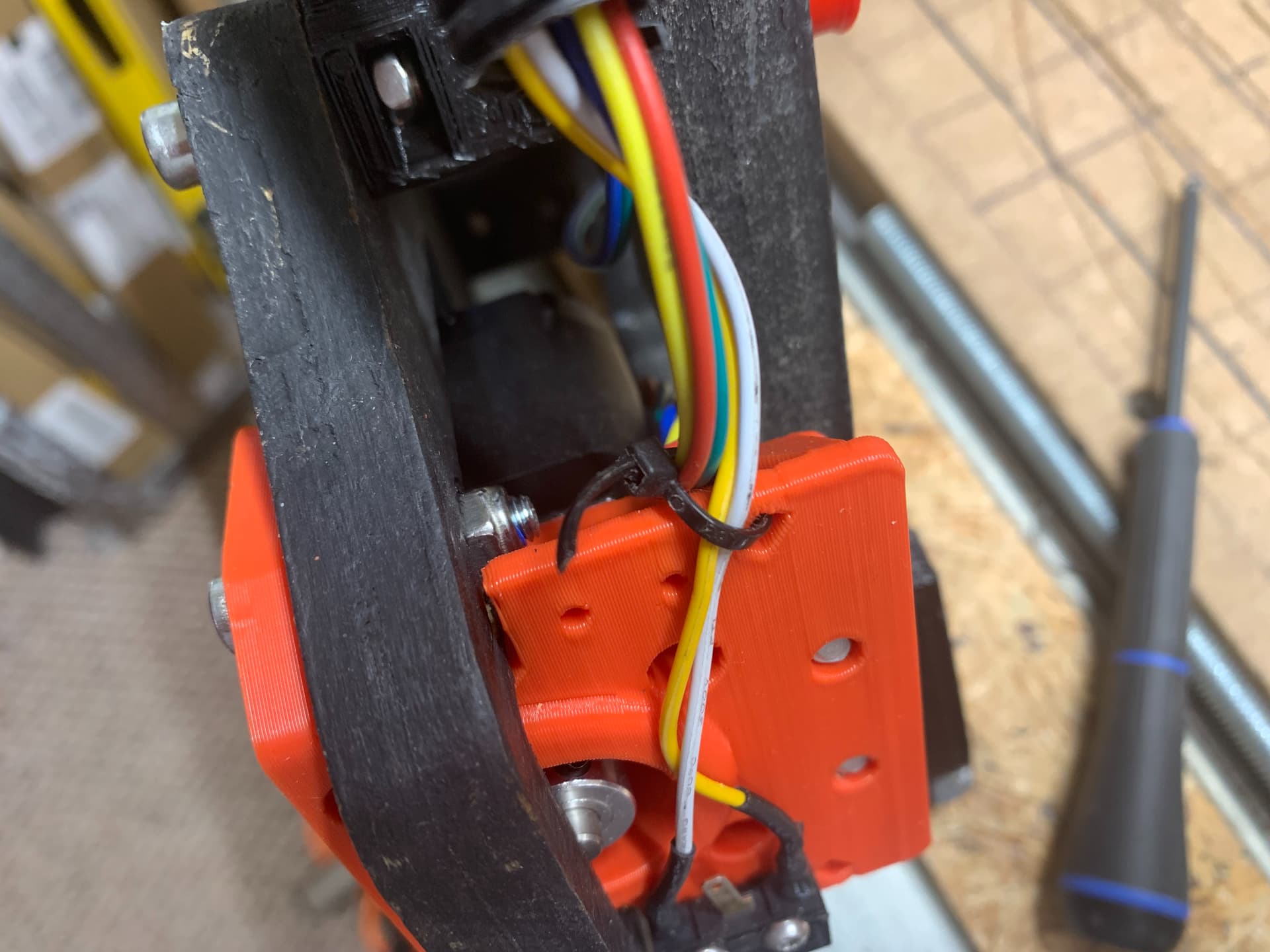
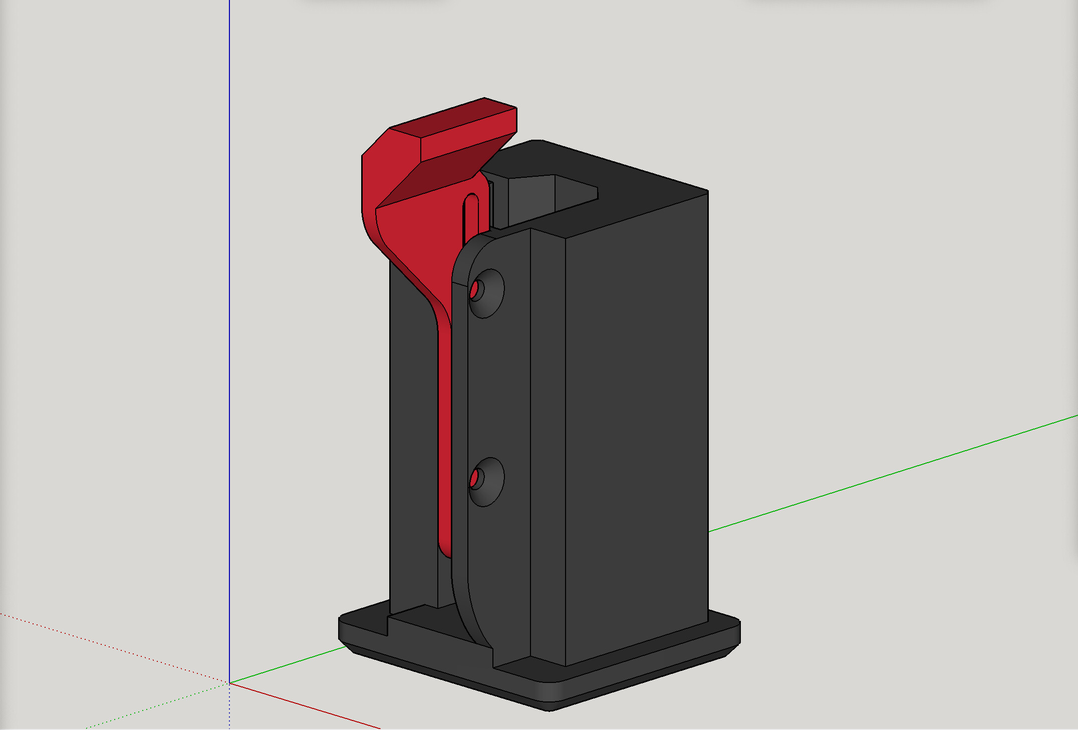
This is another view of the “business end” of my new remix of the Y drive motor mount, showing that the tapered head screws are almost flush due to the counter bore allowance of the holes in the design. The part’s height here is crucial.
Stand-offs: switched to printed (sourcing issue workaround)
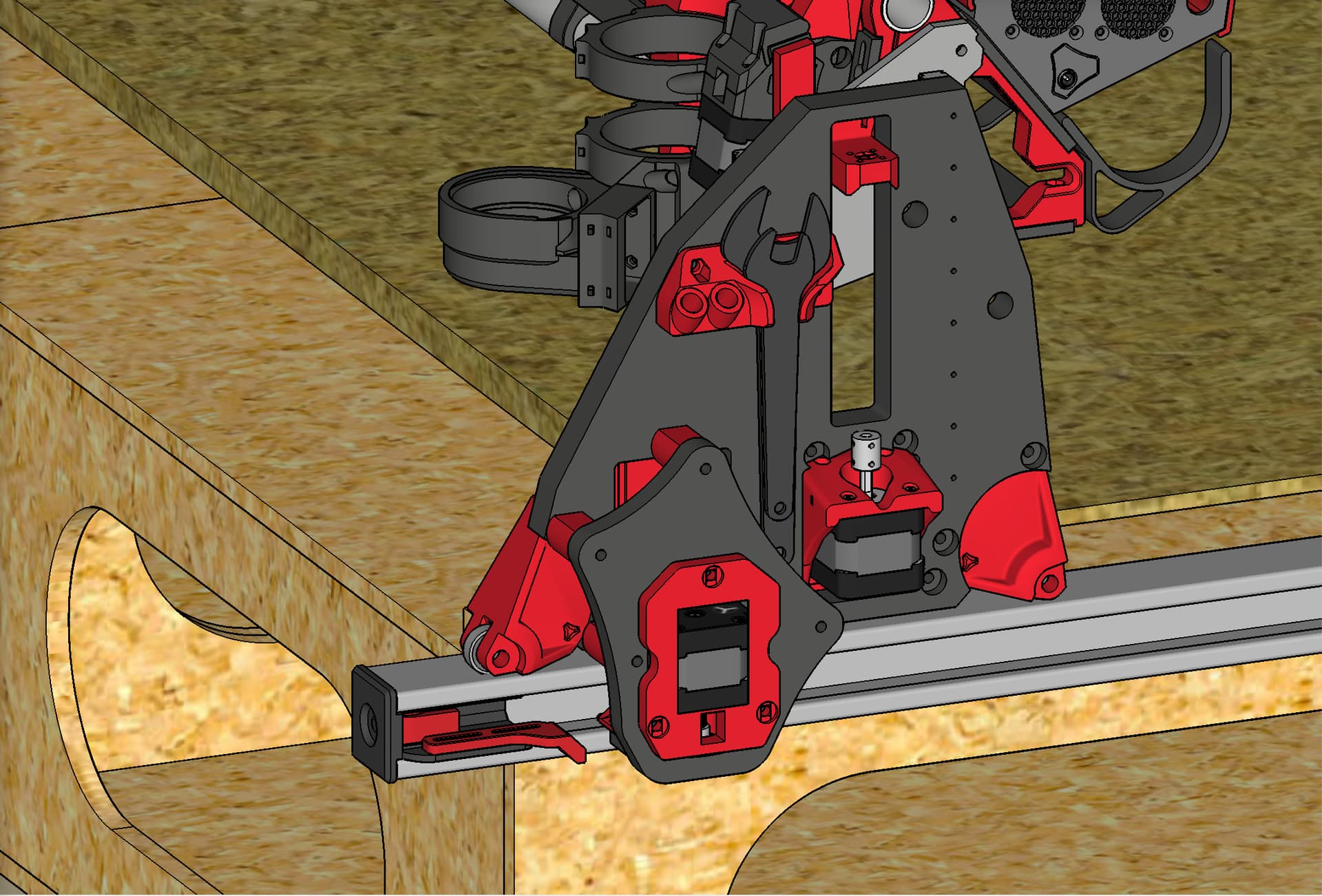
I could not seem to source coupling nuts (hex bar) at the right length and thread size, so I designed printed standoffs that have nut capture slots for M5 nylock nuts, and used two nuts and two M5 screws per stand-off (coming from “outside” on both sides) to secure the secondary Y plate to the stock YZ plate. They are oriented for printing so that maximum strength is in the direction where it’s needed.
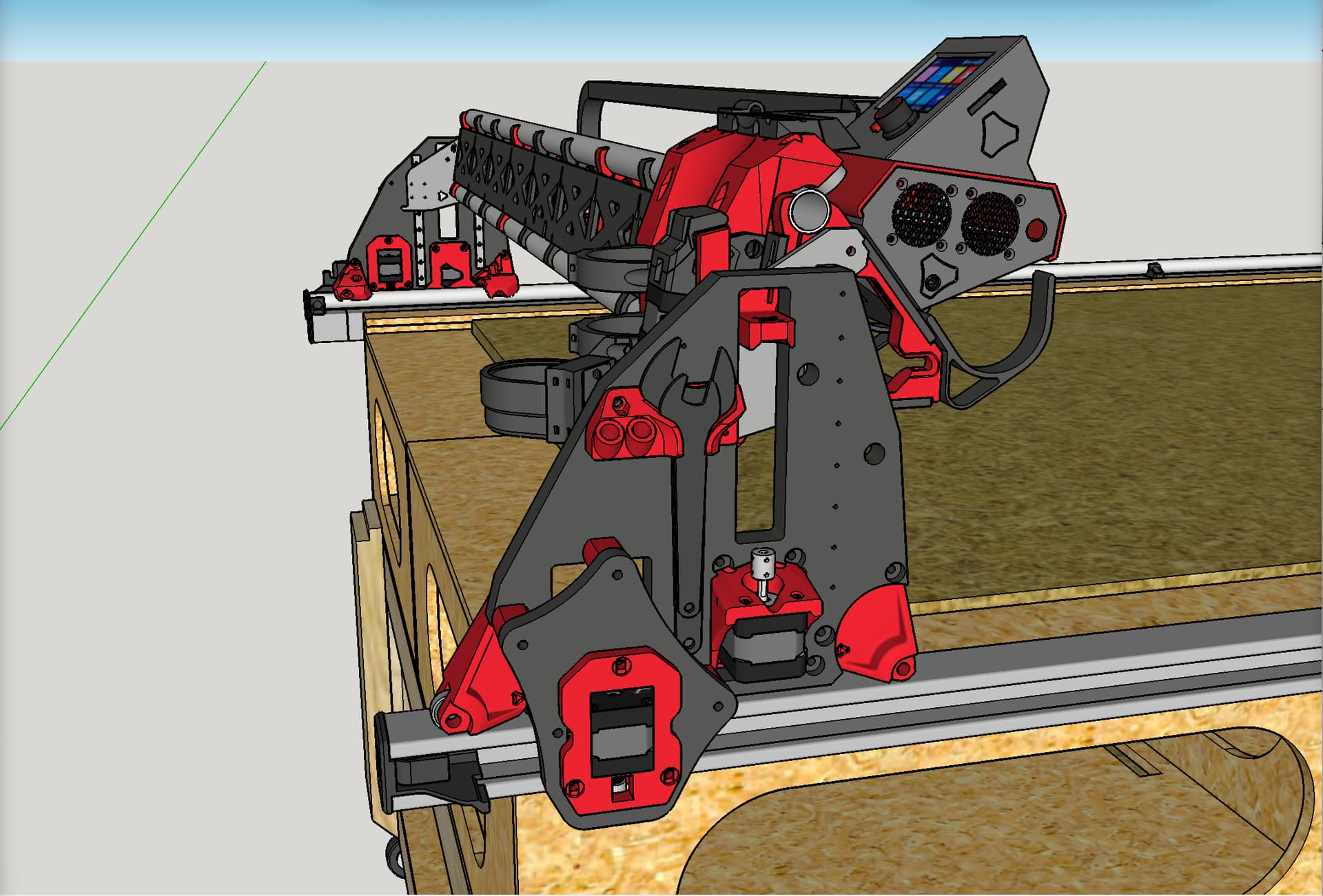
This view is while the LowRider is “flipped over” somewhat, looking at the bottom of it so to speak. All the standoffs are installed on stock YZ plate, and the secondary Y plate is installed onto them. There are four of them.
As of now I have the system setup and working. I’m tweaking the belt tension system so it’s homing end stop is located square to the other side, which is not being modified in this way, as I only need the belt out of the way on this loading side of the table, and doing this mod on both Y sides would mean the gantry could only be removed and reinstalled by “sliding” it out of the ends of the superstruts. As it is I can insert the mod’d side into the superstrut and then lower the other onto the Y rail.
I’m pleased to say it’s working great, and I’m working on some video footage to illustrate.
Yep, I used the Paulk workbench torsion box as my inspiration, and designed and made two long torsion boxes, as well as a sturdy rolling cart base, and that’s what I use for my big router-based LR3.
I decided to create an “adjustable endstop” version of the end cap-tensioner set for this mod.
Getting “square” can always be done with Marlin M666, but this allows a tangible, old school physical correction path as well. Also, whereas Marlin M666 can only adjust in one direction so to speak (inward from the farthest out end stop), thus “losing” the travel distance needed for the correction, this physical method allows adjusting outward (if the adjustable side is too far in) thus “gaining” the travel distance instead of losing it.
It’s designed to use two M3 screws, washers, and nylock nuts, to allow the end stop “slider” to be adjusted.
Doug this is fantastic.
I’ve started to work on an LR2 to LR3 upgrade and one of the things I was concerned about was losing that extra workbench the LR2 provided. Just thinking about the change made me aware of how much I use it.
Your solution looks perfect and it resolves a small issue I had with the exposed belt design: every visitor to my workroom has had to hear me say “Oh, uh, don’t lean on those please”
So, every time I came in, I had to tell myself that same advice! Not anymore!
I keep recording video to show everyone, and then I make some more changes/improvements and then want to re-record. I am hoping I can just get something useful edited out of all these clips I have!
The superstrut can vary slightly in the span across its opening. For most of it, the measurement was north of 22mm, although occasionally it measured less than 22, and in a couple of places barely over 21mm. (It’s not a precision machined product.) So I designed for it as though it were “21mm or even less” — and targeted the bare minimum height in which I could accomplish a design of a functional part, which seems to be 20 mm, and that is only achievable by not putting nuts on the ends of the screws that serve as axels for the pulleys, and by countersinking the heads of those same screws into the printed part. Lest anyone think that the axel screws could accidentally come out during a job: there is a lip of steel of the superstrut riding just above the heads of those screws, so they literally cannot come out during operation.
If you do this mod, trust me when I say that you will want an air gap between the “business end” of the new Y Drive mount and the upper lip and lower lip of the superstrut, at all places in the range of motion. While I was working with an early prototype in which the portion of the printed part (with the pulleys in it) was a bit taller, there was a slight contact — a faint brushing of the Y drive mount against the smooth lip of the superstrut. Instead of immediately redesigning the print part, I did some testing, and found that the slight contact eventually increased to a more firm “friction interference” type contact during operational testing. My theory is that the warmth of the stepper motor may have caused the plastic to expand slightly. Whatever the cause, the result was that a “braking effect” of the contact became an issue that could not be ignored. I redesigned the part to go from “almost as short” as 20mm to actually being 20mm. That gave me a smooth ride with air gaps at top and bottom, throughout the full range of motion, and I have been able to successfully complete multiple, multiple full “torture test” type work jobs flawlessly.
My recommendation for testing regarding clearance is to set up some “torture test” type work jobs, and cycle through them (at first) with no power to the router, and no bit actually making any cut contact with the material, and no dust collection noise, and listen for “the sounds of silence.” Ideally you should hear nothing but the stepper motors. If you hear any faint sound of plastic of the Y drive mount sliding along the steel of the superstrut, then it’s making contact somewhere, and your positioning / alignment need corrected. Also, visually inspect it carefully during the full range of motion. You want this thing to have no risk of its movement efforts becoming like stirring peanut butter with a spatula (because of some heat expansion or whatever). You don’t want it “sliding” — you want it “gliding” in air. Its motion should be effortless.
I will be making the files for this available publicly soon. I had given early access to my Patreon supporters. However, I later made an administrative decision to delete my Patreon. The files will soon be available for download from my Printables page here.
@DougJoseph
Are you still considering releasing these designs since you’ve retired your Patreon account?
I’m not quite ready to start the rebuild but it’s getting closer with most parts printed.
Would buying you a ko-fi encourage an early release
yes, still planning to release. I’ve been trying to balance obligation to the patrons from before I retired the account with the desire to go ahead and release. Any and all kindnesses shown re. cookies and ko-fi are always appreciated.
Thanks for this Doug!
I read through the printables notes. I think I may try without the strut. Use a slight table overhang and possibly box it on the bottom. Should simplify alignment too as the opening will be bigger but I’ll have to see what belt parts need rejigged.
Sounds good. The existing stock LR3 belt holders/tensioners get completely replaced in this mod, when used with metal strut as shown.
One option would be to remix the “endcap” for side mounting or top mounting. Another idea would be a remix of my “table extender” mod, or some combo that lands you at the right place.
Good morning Doug,
trying to manufacture the Y-extend Plate using Al .5" but run into several problems with skp file. First, don’t have SkethUp, so extra difficult. We are using FS360. Online conversion from skp to dxf generates a lot of nodes on the profile instead of smooth arcs. These nodes act like starting and stopping points for our tool during cutting, and rather than cutting along a smooth path, this will cause an effect that looks similar to “chatter” when machining the part. Can you help? May be STEP file or a clean DXF and you will make my day