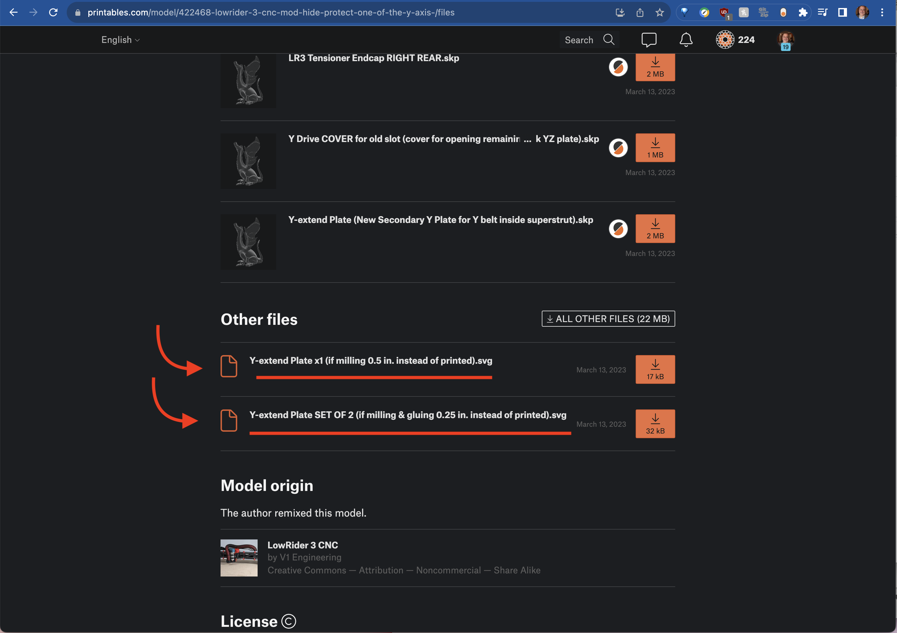
Hey! Glad to hear you are making this. Wouldn’t the SVG I provided in the Printables listing work? Or at least be something you could use to convert to DXF?
Thanks, Doug!
Yes, this is where I started yesterday.
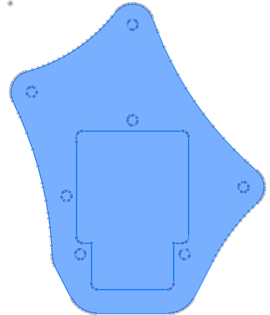
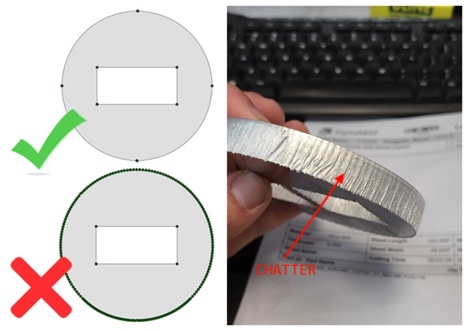
The problem is the SVG is formed with a lot of arc, creating the chatter. I attached the FS360 view below.
Any ideas will be welcome.
Thanks!
Did you try trochoidal milling? This looks rather a problem with the CNC than with the CAD.
CAD problem. By The way, using CO2 laser for cutting this and the chatter creates an on/off laser. If I was using wood then it would not really matter.
Thanks, Philipp.
1 Like
Having many small segments like that shouldn’t cause the laser to turn on and off repeatedly.
Anyway, if you have Fusion, tracing that design with all of those reference points shouldn’t take more than 5-10 minutes and you’d have a clean arcs to cut with
@jcassar :
Although I wish I could agree with @Michael_Melancon that having multiple small straight segments instead of an arc should not cause a laser to “pause” ever so briefly at each change of segment, I have run into this myself on my CO2 laser, using Lightburn with a RUIDA controller. The little “pause” at each segment causes an extra bit of “burn” where each segment meets another. Very annoying.
In googling just now to see if there might be a software solution, in my case I use Lightburn so I was looking there, I found a mention here:
…about a Lightburn specific feature called “Auto-join selected shapes” or some such. It might well solve the problem for Lightburn.
However, in your messages, you indicated “We are using FS360” — which is to say, your CAM is being done there. In my instance, the CAM is being done in Lightburn. I say this to mention that while you later indicated you think it is a CAD problem, it may well have a CAM solution, and it would likely be a CAM outputting option, or Post Processor CAM option (regarding treatment of segments that could/should be treated as arcs).
PS: Be aware that in SketchUp, modeling is essentially an easy way to “mesh edit” (perhaps what Fusion refers to as direct editing of a mesh), then any arcs or circles created in SketchUp require a choice of “how many segments” in advance (or else the default number is invoked) and the result is a group of straight line segments arranged to look like an arc in the overall “mesh.” So, because of this, having the original source SketchUp file would probably not help you.
@jcassar :
The main reason I think there is a CAM solution on the Lightburn side is that, while I have not personally confirmed it, I found the above post by way of this one:
…In which the OP seems to have marked the other thread (linked above) as the “Solution.”
Also note, that when importing a mesh (i.e. STL file) into Fusion 360, there is a way to convert it to a solid body that seeks to arrive and what could be “built” in Fusion 360 by way of its built-in “base” modeling tools. This could result in a body that would ouput in F360’s CAM options without the chatter.
There are YouTube videos about how to create bodies in that way.
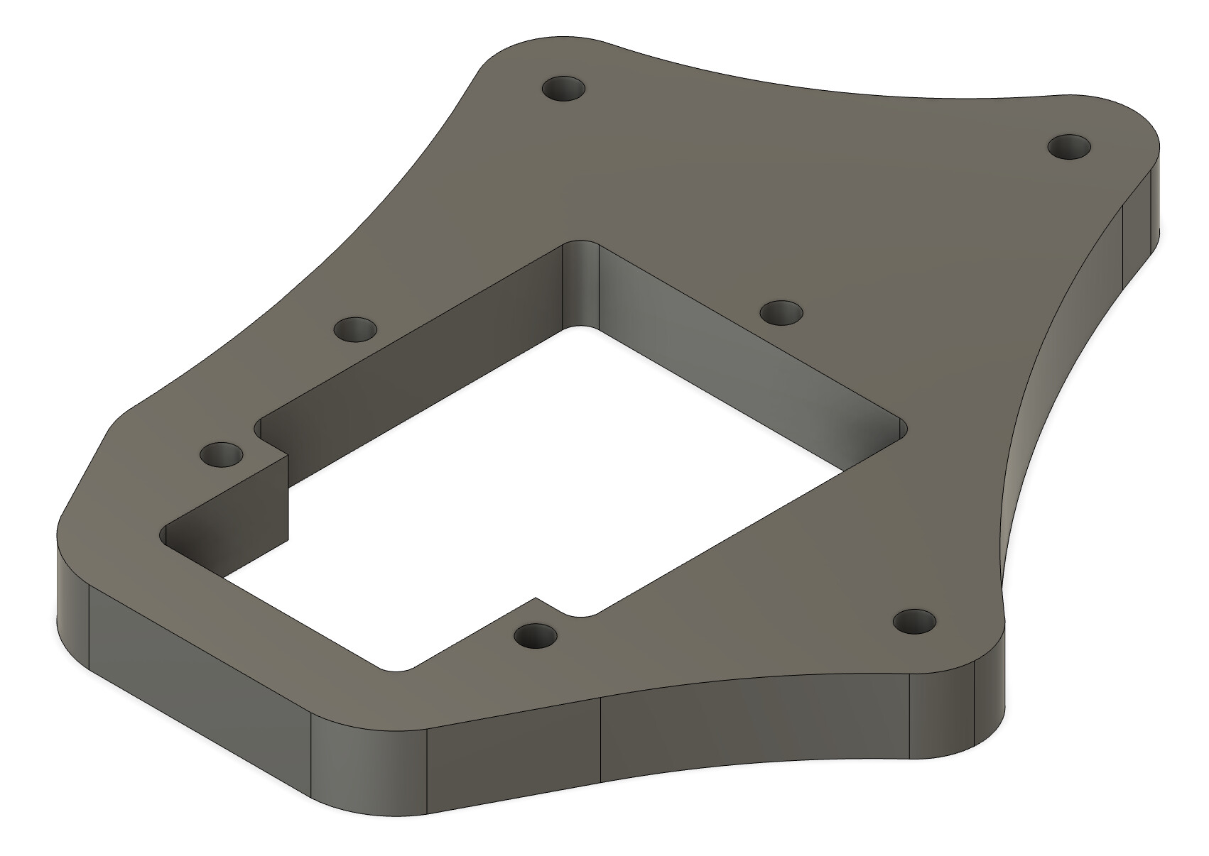
Now, two days, and still not done, so not so easy. The Net is full of articles talking about this, but no join lines feature. Looks like this:
These nodes act like starting and stopping points for our laser during cutting, and rather than cutting along a smooth path, this will cause an effect that looks similar to “chatter” when machining the part.
Well, he said “on/off”. I can understand a “pause” as I’ve seen that happen plenty of times for different reasons with successive commands being processed, but switching the laser on and off is a different behavior
True, I missed that distinction. Off and pause are different. Even a pause would be a problem in cutting.
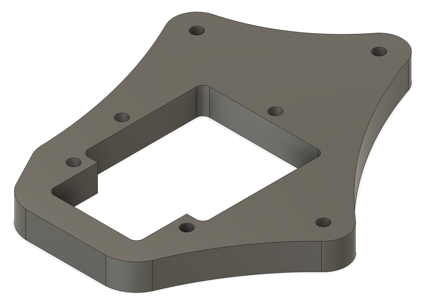
That looks like you just extruded the SVG directly. You have to create a new sketch and use the reference points to redraw it so you have proper geometry
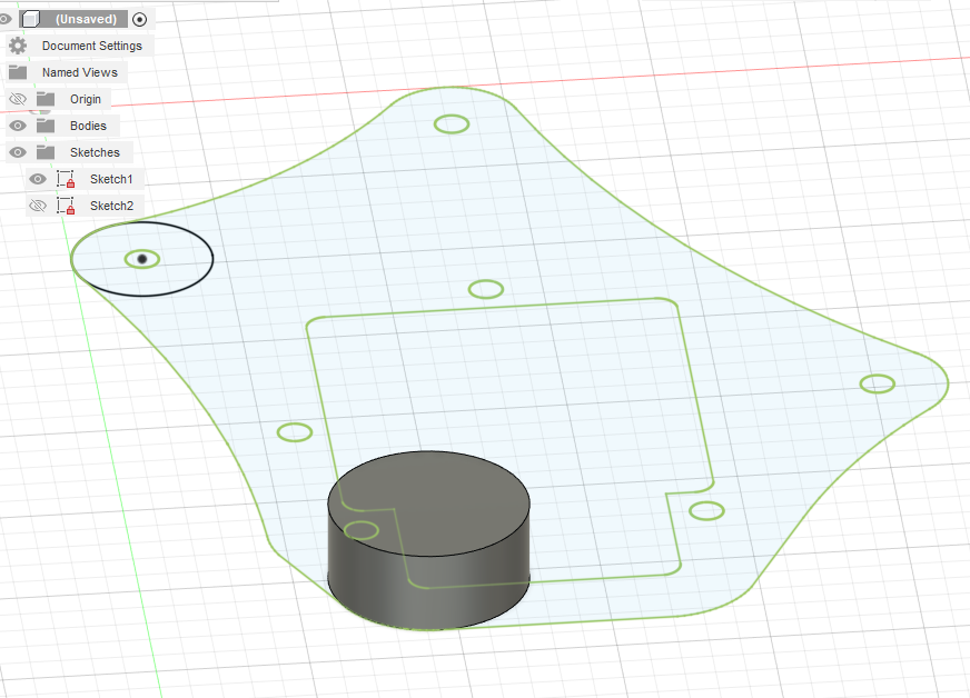
The number of points that are there make it pretty easy to redraw the model on top. The extrusion will then not have all the breaks.
1 Like
@jcassar :
In my recent post, I mentioned this:
Here is what I am getting when I follow a process that I will outline with screen shots:
Here’s the progression, from importing the mesh, to selecting the Mesh tab, to preparing by Generate Face Groups, to Modify > Convert Mesh, and using the settings shown in the screen grabs coming up…
@jcassar :
Continued:
Insert > Mesh:

Comes in like this:
Click into the Mesh tab:
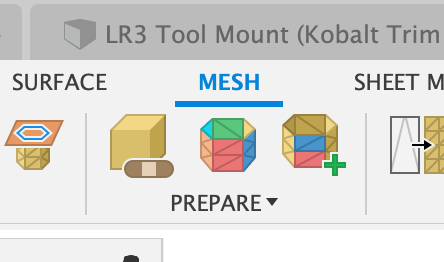
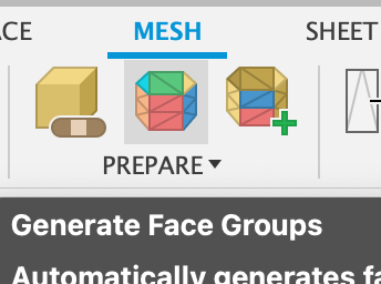
Under “Prepare” click “Generate Face Groups”:
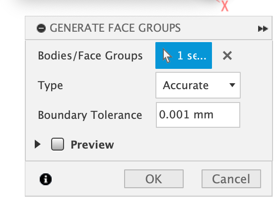
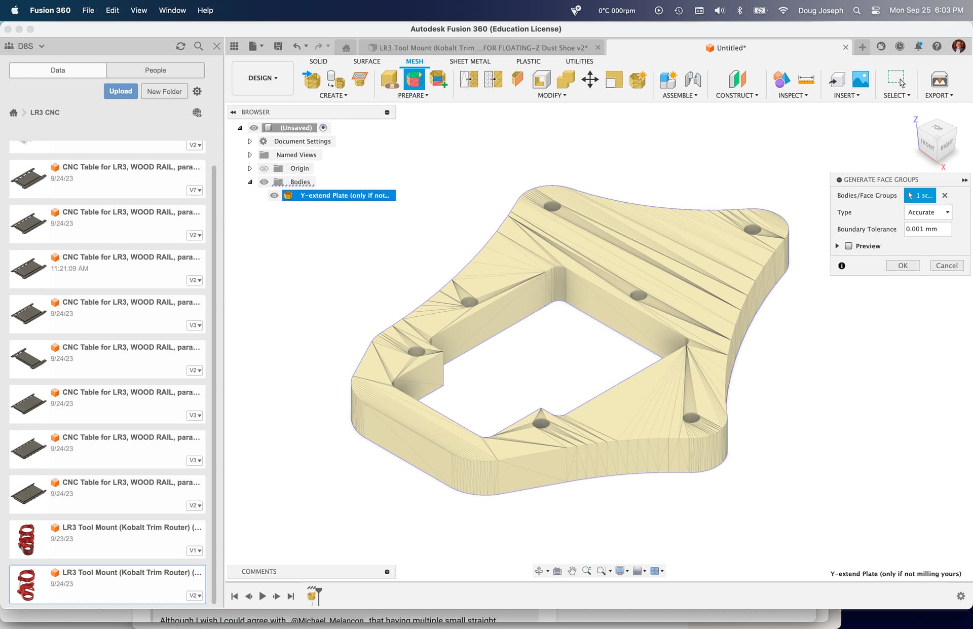
Select the mesh you just imported, set to Accurate, and I used “0.001mm” for Tolerance:
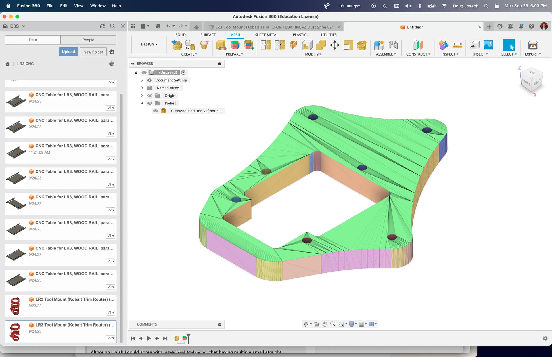
Yields this prepared result with generated face groups:
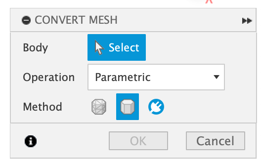
Under Modify, choose Convert Mesh:
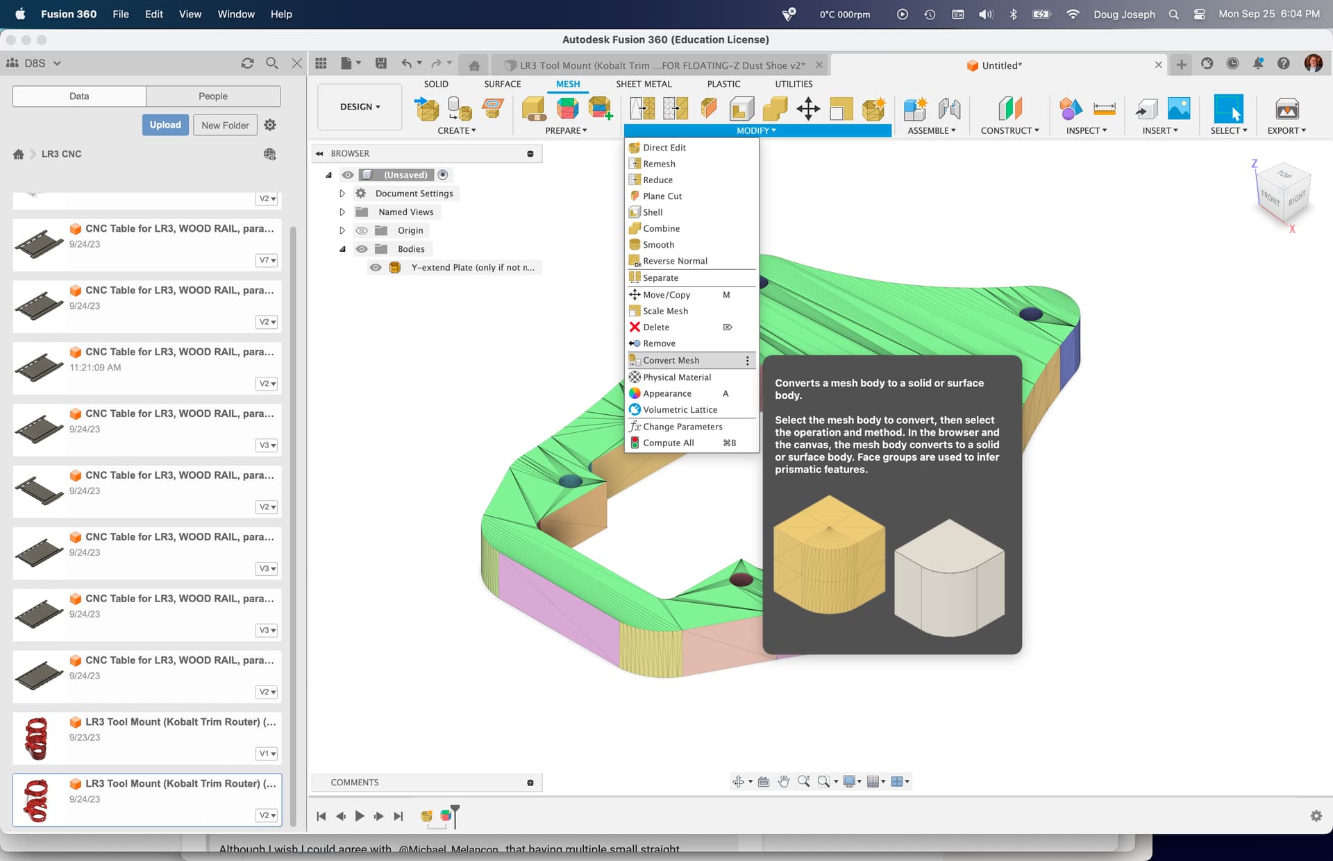
Select the mesh you imported:
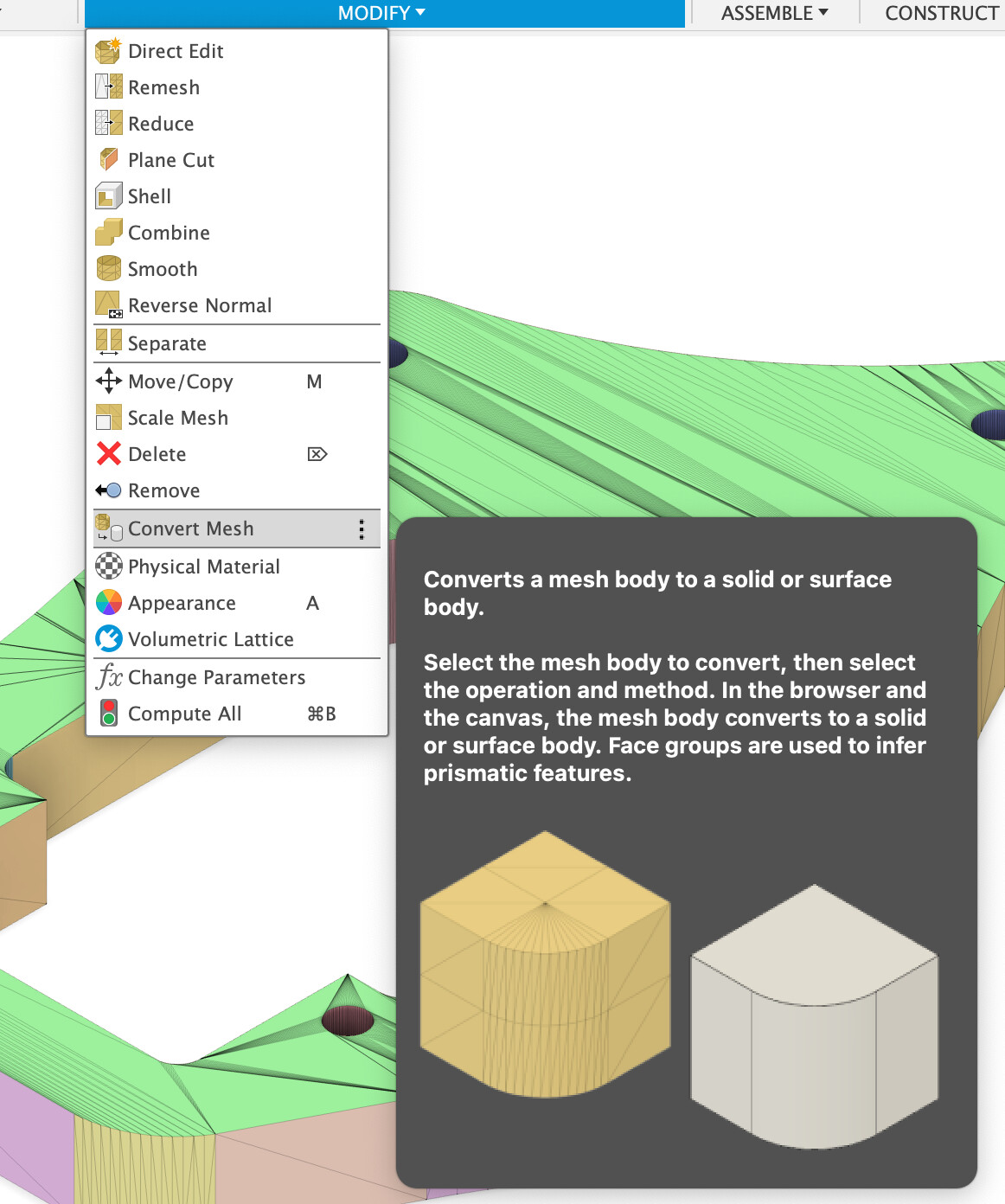
Set to “Parametric” and choose “Prismatic” —
Note: Prismatic may not be present in free Hobby license version. If not and that’s an issue, I’m glad I was able to do this for you.

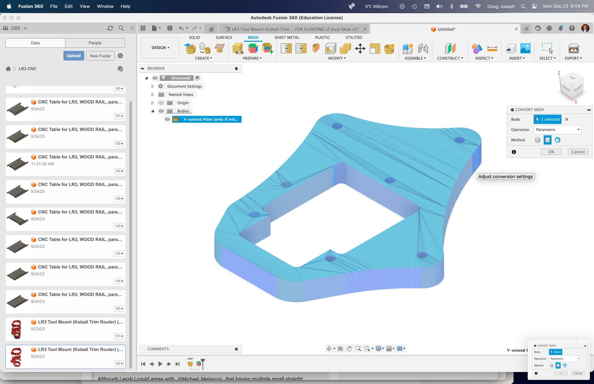
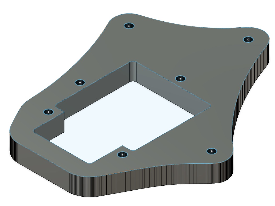
Results in this:

@jcassar :
Attached is the F360 file resulting from the conversion I illustrated above. Mine does not have the segment lines that yours has. Again, I outlined how in the previous post!
Y-extend Plate (as F360 Solid Body with ‘parametric’ base features).f3d.zip (1.3 MB)
Here’s a “close up” of my result as contained in this file:
This method is certainly the easiest way if you have the paid version of Fusion.
For those of us the Free version, the Parametric conversion method is not available.
In that case, you have to retrace it, or manually repair the mesh.

1 Like
Guys,
thanks so much. I completely forgot about the mesh capabilities of FS360. I did that process a while back for another project and works great.
Apologies for all of these updates.
Keep in touch
JP
2 Likes
Happy to help!
1 Like
I didn’t know of the second option and always used the first one. I then cut the body in two parts which would output the result above and then combine the two parts again. No manual retracing needed. ![]() (Or I am missing something.)
(Or I am missing something.)
Just depends on what you started with. At the beginning of the thread he was mentioning opening the SVG and the SVG had the breaks in it as well. If you extrude that, you get the same bad geometry.
For such a simple sketch, drawing a few circles and straight lines, for me, is faster than trying to fix the mesh, with the added benefit that you are left with a proper sketch driven model that is easier to make edits to.
If starting with the STL, then definitely mesh editing would be the direction I go. Although I’m still a rookie with it, and struggle to ever fully get an STL completely cleaned up when there are curves involved. Especially Sketchup exported STLs. They tend to have much worse geometry and overlaps, so even the delete trick can’t even clean up the flat faces.
I also am not sure exactly what you mean by this. To be honest, for raw mesh editing, I usually just bring the STL into Blender and do it there if Fusion is struggling to help me out.
I really need to spend more time learning how to clean up STLs and turn them into proper Body objects… it makes for crappy looking reference models ![]()
1 Like
Let me correct this… Parametric is there for the Free users, it’s the “Method” option that is restricted.
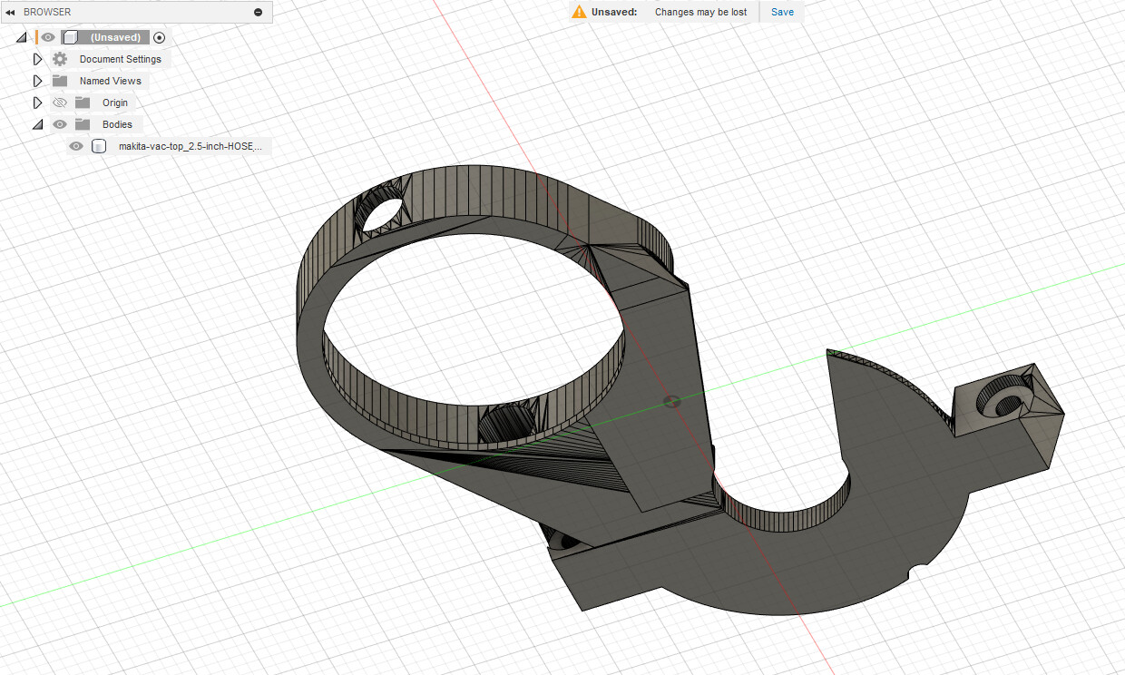
We don’t get the 2nd option which is “Prismatic”, we only get “Faceted”, so the result looks more like this:
Sometimes, you can click Delete on a few faces on flat areas and it will auto-repair and get you a better looking Body in some flat areas:

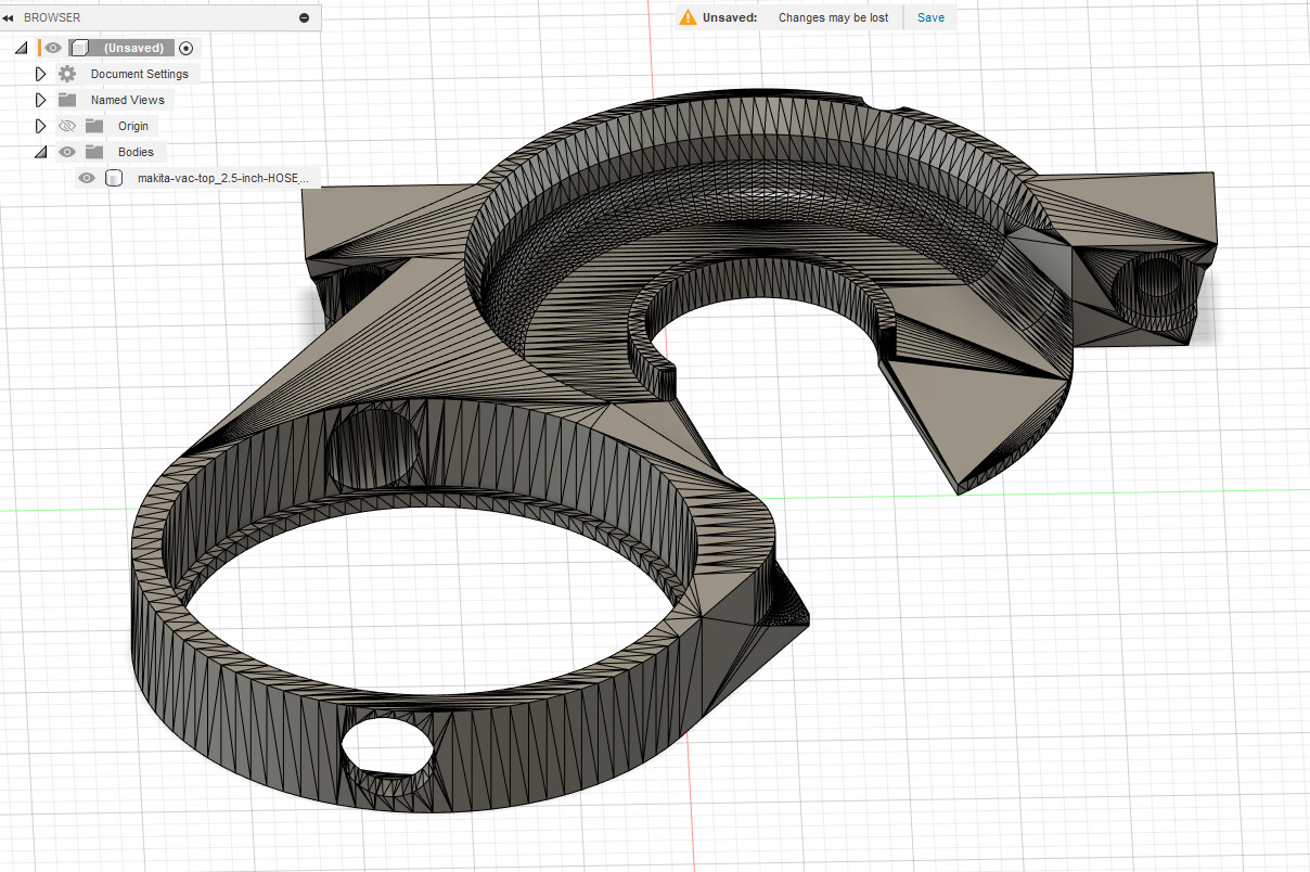
But sometimes, especially from Sketchup, Fusion just can’t handle it, and you end up with stuff like this:
At this point, this is where I struggle to manually get it to something that even remotely resembles what would come out of that Prismatic option.
1 Like