Yes, that was my understanding as well!
Here’s what I know: My CAD experience is limited, and limited to Onshape to double the trouble!
Once a solid has been exported to an STL (or STEP?) file it is rendered as a mesh, whether you can see it or not.
I understand that a Parasolid is a true render - but that all gets a bit tech for me - it’s easy to do a search on how to convert to a parasolid, not so easy to understand what that is or get the software!
Trying to create a parametric model from a mesh is probably not possible in the context of what we are trying to do here as far as I can see, so yes it is quicker and easier to draw the entire object from square one.
If you just want to "clean up STL’s for appearance sake - Onshape has a view option “Shaded without Edges” and I am sure that Fusion has an equivalent. Be warned that the mesh is still there, it’s just invisible.
1 Like
Oh, it’s never purely for appearance’s sake. (Although the rough appearance does annoy me)
If you need make edits, or even aligning things, it’s more difficult to deal with in Fusion when the body is all broken up. Inferencing tools, alignment tools, and many of the tools on the “Solid” tab don’t work properly.
Fusion does it for you with the click of a button…if you pay to access that button. It can be done manually, but I’m not very good at it, and I have to go rewatch videos every time I try, and still have limited success.
3 Likes
I really have to take screenshots of my workaround. ![]()
1 Like
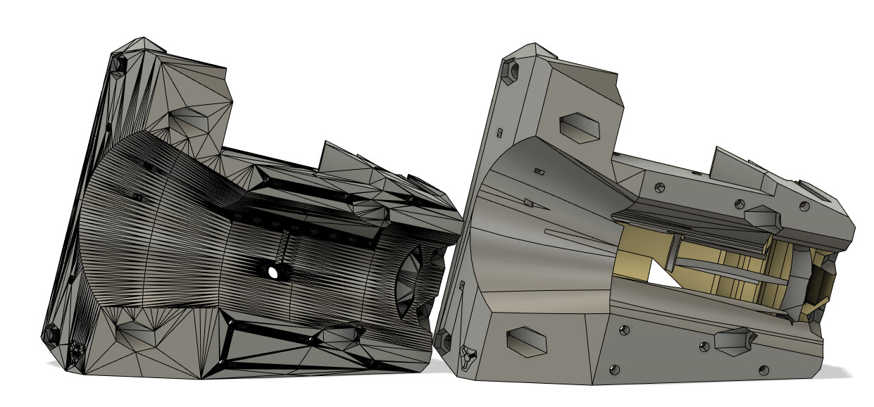
That would be great. I got a redo of my free trial, and that fancy button has failed on 50% of the models.
Rail Rollers and the LR Core have chunks missing out of it. The Prismatic function can’t work it out automatically from the mesh. Of course all the videos of it in action work perfectly, but I am unimpressed so far.
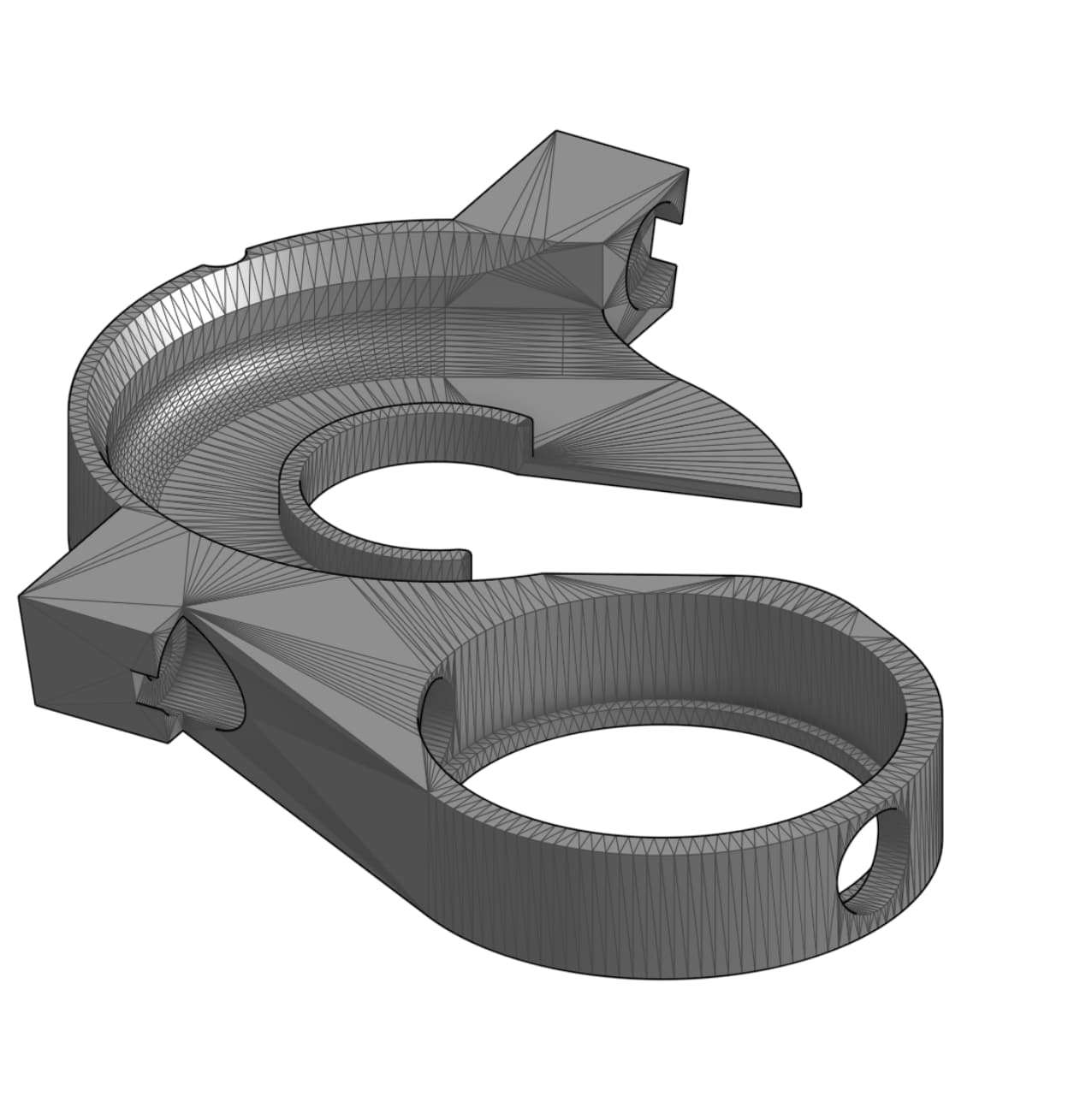
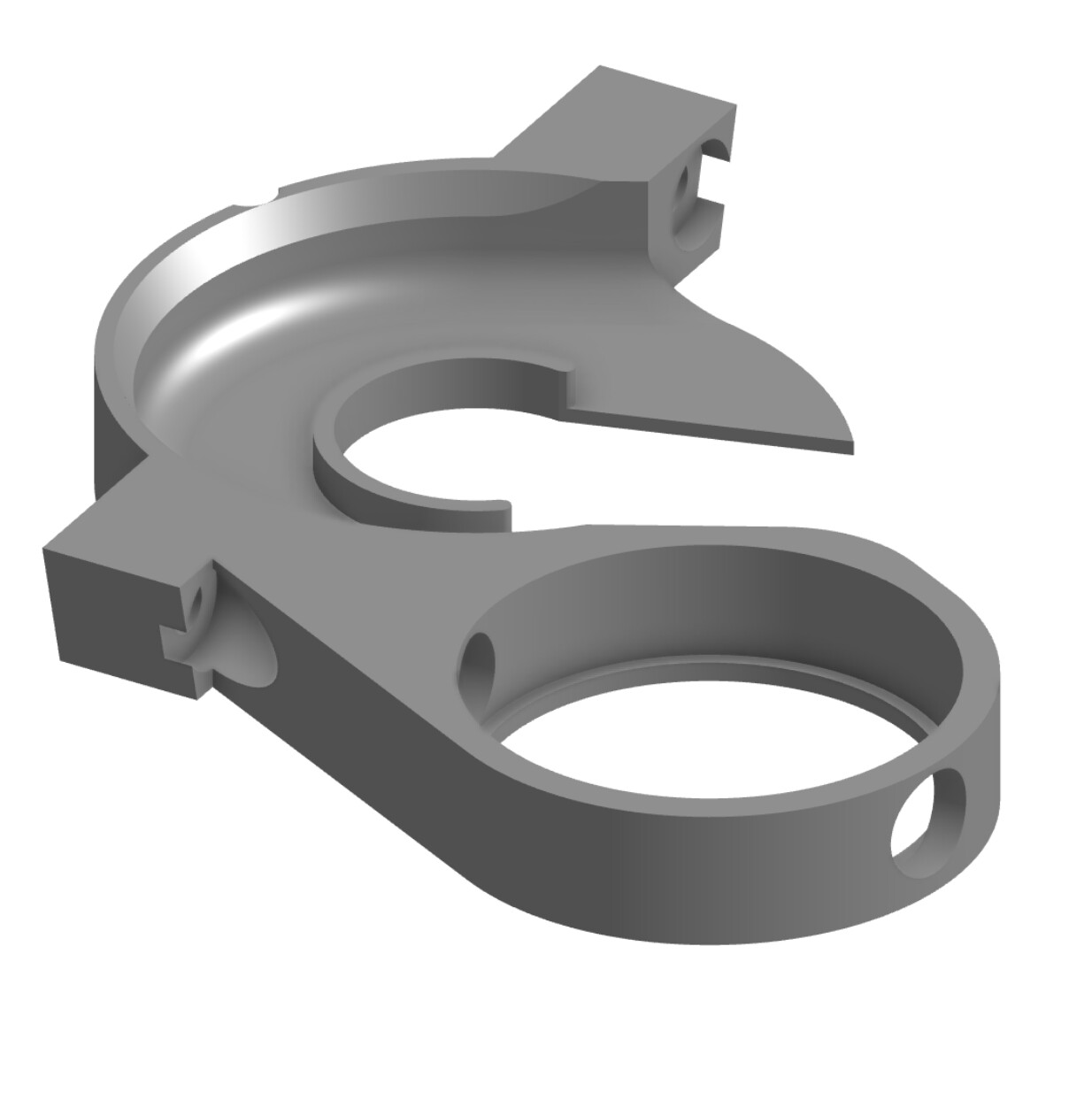
At the moment, these are the results of the 2 different Fusion “auto mesh to body” conversions
1 Like
When the preparation step by creating face groups has created separate colored areas within a single arcing section, then, if you don’t manually combine the disparate face groups together into one face group, the resulting effort by the prismatic convert will separate those areas, and there will be a line slicing the arc area apart. Carefully checking and combining face groups can help get a better result.
I find myself often in need of an ability to break apart face groups that span across areas where a single face group should not have been that big. I noticed that face groups of small tiny details can get totally missed by the prismatic feature. I think their (Autodesk’s) assumption is that the tool is going to get you part of the way and you need to do some modeling to finish up, but that is very frustrating.
I did play with the face groups a little bit, but didn’t really spend a ton of time with it yet.
Some of the conversions were even worse.
The reality is, I know I’m not going to have the paid version long term, so I’d much prefer to learn some tricks and efficient ways to re-model these things correctly in the spots that I need.
I’ll probably play with it a little more tonight
1 Like
I see litigation in your future…LOL -But, tacless strip would sure do the trick - way to “Go Medieval” on their ass…(I so do love any chance for a “Pulp Fiction” reference…grin)
1 Like
That takes care of one of the concerns I had with the y axis belt on one side being exposed, but if going through all the designing to both place the belt within the Strut (Superstrut/Unistrut, don’t know what the most correct term is) and figure a way to make most of the belt attached to help prevent problems with unequal stretching - why not just use a screw drive rod?? Newbie question I know, but still really trying to wrap my head around all this new technology/terms.
Postscript - I just saw the prices of even narrow-diameter threaded drive rods…I get it now - reasonably priced and obtainable by “Joe Average” CNC machine…forget the whole concept through the trees I guess…
But couldn’t you use a more simple threaded rod which would be much cheaper or is the spacing of thread/teeth of the belt that important? 1/2" threaded rod 10’ long is only $15, couldn’t that be used as a ball screw/rod?
1 Like
Wow, that’s a lot of points in that SVG, you would definitely want to optimize that by deleting quite a bit of those points but that would still keep the original shape most points besides the middle and two end points can be deleted while still maintaining the same curve/arc. There are a few freeware vector drawing programs like Inkscape that you could use to optimize that shape and get rid of all those points in the curves if that’s causing problems when extruding in the cad program. Most vector programs would convert points at the end of a curve to bezier curves with handles that you can adjust to keep the original arc/curve radius.
Those are both brand names. One of them is the original creator of the metal strut. The other one is a company that came along later, making a competitor that for all practical intents and purposes is basically identical to the original.
NEW on the Printables listing, as of today:
- January 15, 2024 - for the secondary Y-plates: uploaded a revised SVG with vector curves instead of node-ridden groups of line segments, as the unnecessary nodes can cause detrimental pauses while lasering (for those who laser cut the plates). Also added DXG file format of the same. Also, for the adjustable end stops, I uploaded revised STL files that have a bigger “target” for the end stop switch to hit.
close older topics to help with spambots, and faster new user questions.