OK, as discussed at length over here… and after much work and achieving a system that has been working flawlessly for me for quite some time, succeeding on lots of cut jobs, I got this mod posted on Printables:
Click to download:
LowRider 3 CNC mod: HIDE / PROTECT one of the Y AXIS BELTS inside metal strut / unistrut / superstrut) (v1.0)
The following is copied and pasted from the Printables description:
AKA “LR3 Superstrut-encased Y belt”
Due to my room configuration limitations, I must always load material (including full 4’ x 8’ sheets) onto my LowRider v3 CNC’s big table via the long-axis, near side (usually designated Y, although I have my X & Y axes swapped). It is inconvenient to continually detach and reattach the near-side long belt, and leaving it in place for loading and working means it is always in the way and at risk of being damaged.
Here’s my solution, which is working flawlessly:
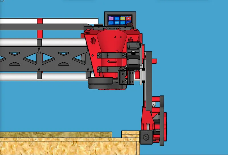
Instead of having my near-side long belt riding up above the table, I have it hidden and protected inside the metal strut that my LR3 rides on. (Metal strut such as this is sold under brand names such as “unistrut” and “superstrut.”)
As I discussed and explained on the V1E forum, the new setup is working flawlessly over the course of many, many cut jobs. I’m super super pleased. It’s exactly what I was hoping for!
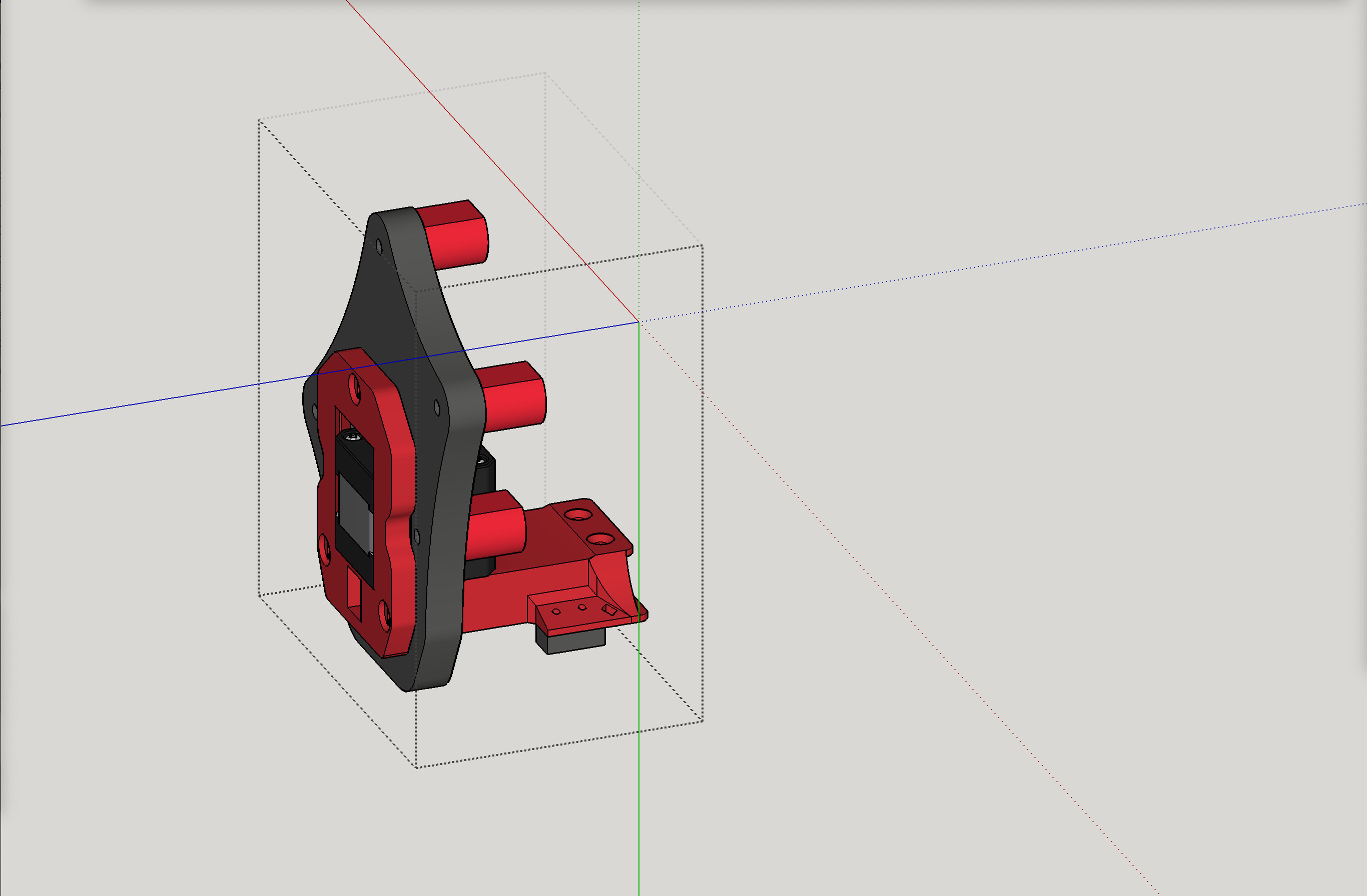
To accomplish this, I designed and installed both a new quick-release belt-tensioning system for inside the superstrut, and also designed a new Y motor mount replacement that moves the Y motor to make use of the protected, hidden belt in the new location.
Benefits include:
- Belt is protected from having tools, materials, and hands catching on it, dragging it, pulling it, etc.
- For those who, like me, due to room and LR3 orientation, must do their material loading and unloading via the near, long side of the table, the belt would not be in the way.
- Belt gains great protection from dust, debris, potential sources of cut or burn, etc.
- Coolness factor x10.

Please consider a couple of things:
- Even if you are not running your LR3 on superstrut metal, you could still do this, by simply remixing how the new tensioners attach underneath whatever table edge or “lip” you are wanting to hide the long belt under.
- Even if your LR3 is running a bit farther away from your table’s near-side long edge than mine is, you can still do this by simply increasing the length of the printable “standoff” file, via a remix.
The pics below show the plan and results of me getting this developed. But first, regarding the downloadable attachments, I offer:
- SketchUp files
- STL files
- SVG files
The SketchUp files are to make it easier for remixing as needed. The STL files are printable. The SVG files are for cutting the new secondary Y plate out of 1/2" MDF (or 1/2" plywood), and there is a “single” plate drawing (for one) and a “2-up” drawing that would print two plates — so that if you are cutting 1/4" thick plywood x2 and gluing them together to make 1/2" (as I did) then cutting two is prepped for you. Let me know if you want to do this and if you need any help from me on it!
Print info:
- I used the same slicer settings as for most LowRider 3 parts.
- Print as oriented.
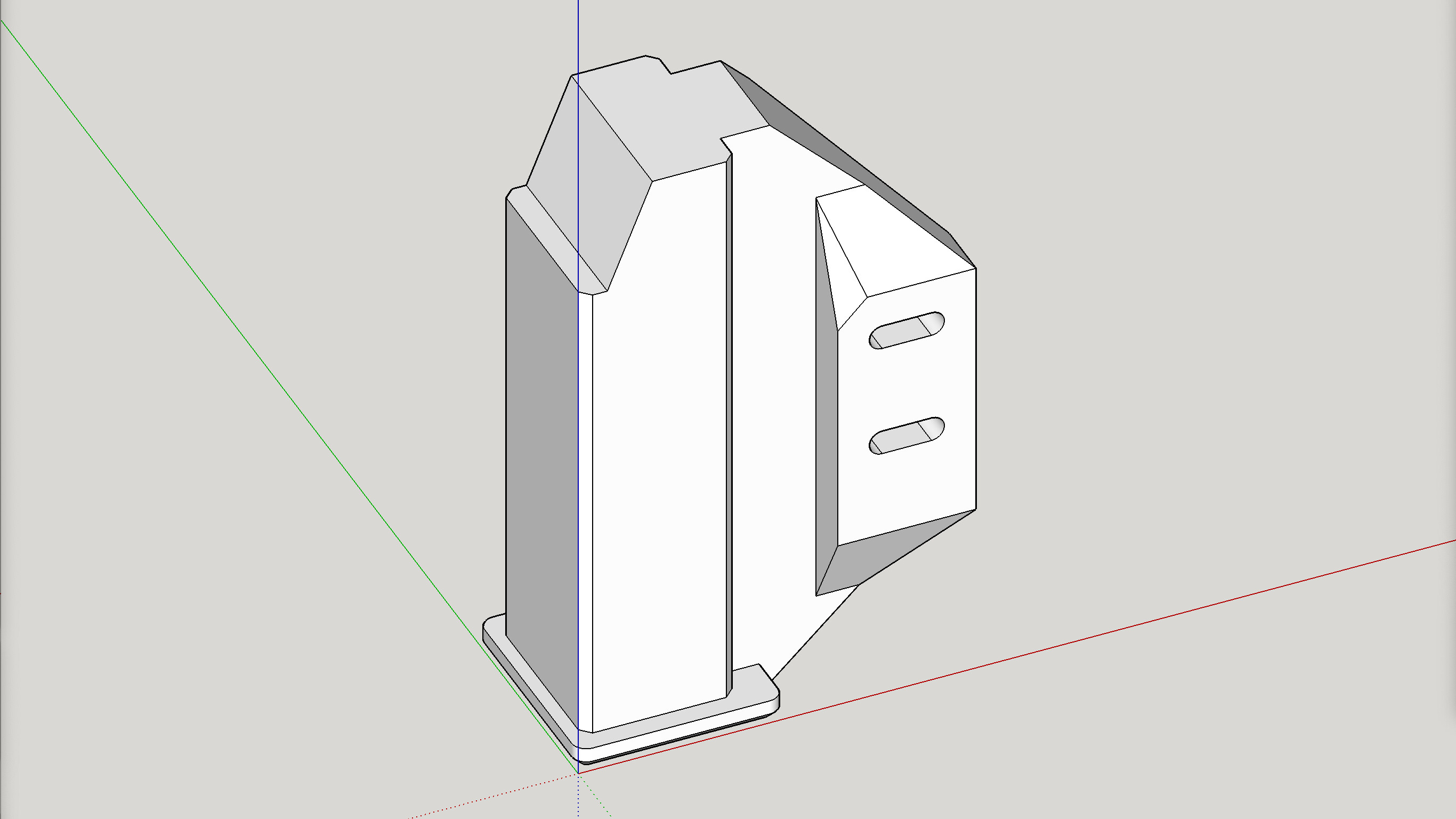
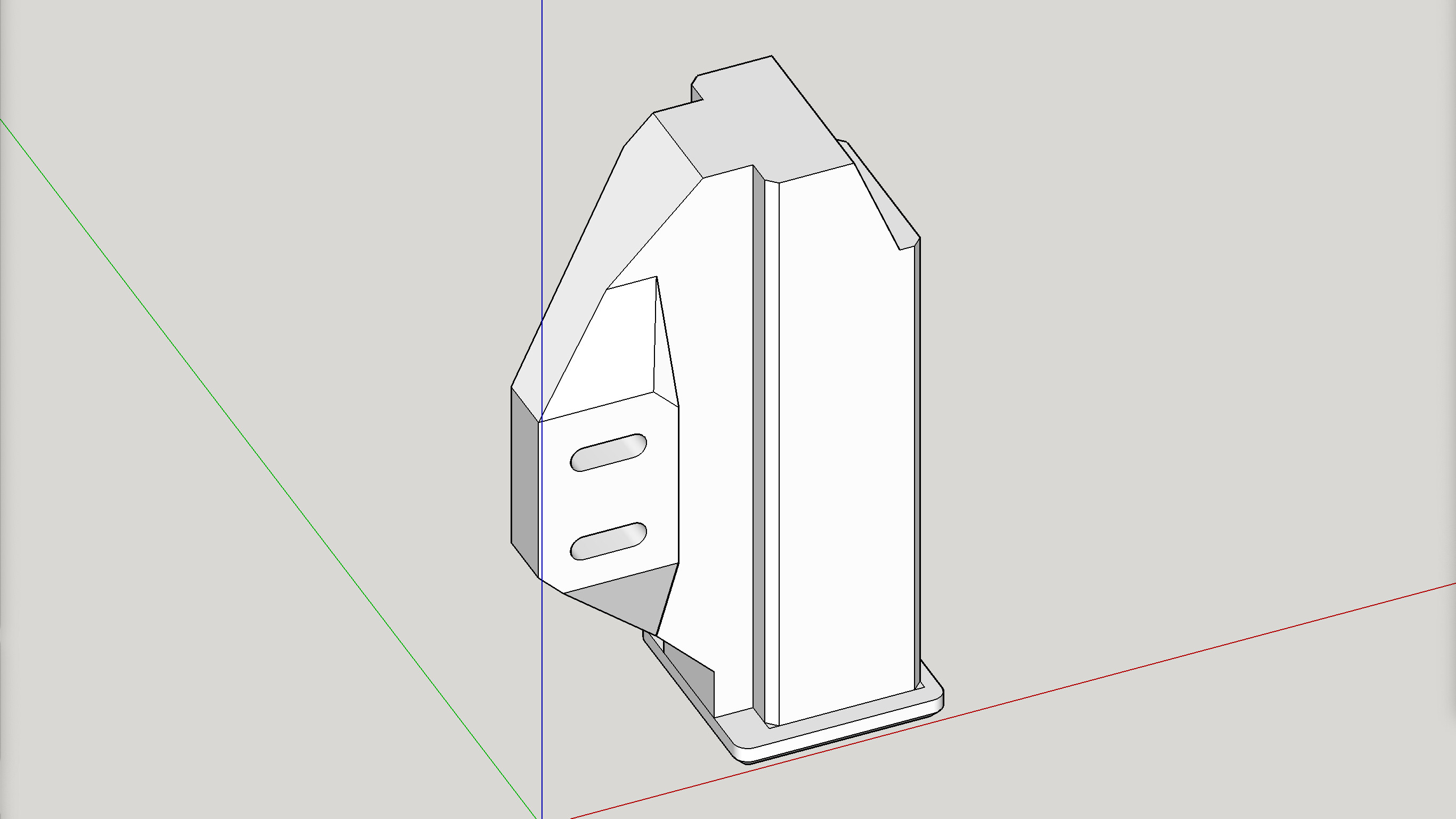
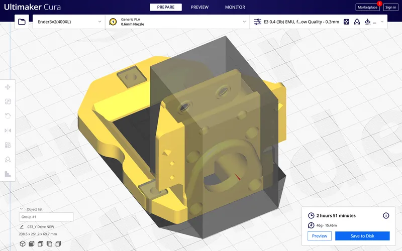
- The printed part named “Y Drive NEW.stl” needs some supports, but see image below for how I used support blockers in Cura to constrain supports to only limited areas of need.
Assembly info (new Y Drive Mount and new belt tensioner system):
- REMOVAL OF OLD
- Remove your near-side Y stepper motor, and its old mount. Save the screws and nuts to be reused. By “near-side” I mean the side of your LR3 that does not have the EMT guide tube on the Y axis.
- Also remove the endstop switch from the mount and lay it aside to be reused. Same screws will be reused.
- Also remove the belt pulleys and set them aside to be reused. Note that the screws that held them are not reused, just the pulleys.
- The old drive mount is no longer needed. Display it as a trophy, or save it for in case you change your mind and want to go back to the dark side. LOL
- Remove your near-side Y stepper motor, and its old mount. Save the screws and nuts to be reused. By “near-side” I mean the side of your LR3 that does not have the EMT guide tube on the Y axis.
- NEW Y DRIVE MOUNT
- The new Y drive setup here is much like the original LR3 Y drive mount, except this time the motor and mount are mirror flipped and the motor is moved out and down.
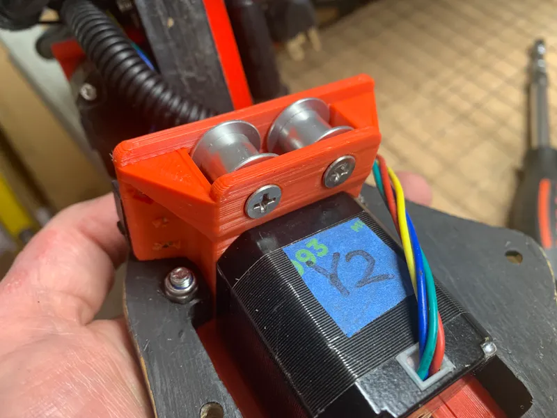
- Using two (2) tapered bore M5 x 20mm screws, re-install the belt pulleys into the new Y drive mount. Remember to not over tighten. They are only biting into plastic (creating their own threads) and they only need to serve as axles. The pulleys should spin freely. Once the setup is complete, the upper lip of the metal strut should serve to ensure that the screws can never accidentally come out.
- The screws in the above step need to be tapered bore, so that you have a smooth surface on both the top and bottom of the “business end” of the new Y drive mount. It’s a 20 mm “protrusion” that’s eventually to be operated inside an opening on the metal strut, and that opening averages about 22 mm.
- Install your near-side Y stepper motor in the new, printed Y Drive mount, using the same three (3) M5 screws and three (3) M5 nuts that were already in use for this purpose.
- Install the mount into the new Y extend plate that you either CNC cut or printed. It should be cut from either ½" MDF or ½" plywood (or some rigid material of your choice), or printed from PLA with lots of infill and perimeter walls (see LR3 docs for same spec for printing XZ plates).
- Re-install the end stop switch for homing. It does not matter which way you have it flipped (blade opening toward inside or outside). The new printed end stop that the switch is to contact is a full width part, so either orientation works. Secure the switch’s wires in place with a zip tie, passing it through the provided zip tie slot.
- Using two (2) tapered bore M5 x 20mm screws, re-install the belt pulleys into the new Y drive mount. Remember to not over tighten. They are only biting into plastic (creating their own threads) and they only need to serve as axles. The pulleys should spin freely. Once the setup is complete, the upper lip of the metal strut should serve to ensure that the screws can never accidentally come out.
- The new Y drive setup here is much like the original LR3 Y drive mount, except this time the motor and mount are mirror flipped and the motor is moved out and down.
- STANDOFFS —AKA “Coupling Nut Spacers”
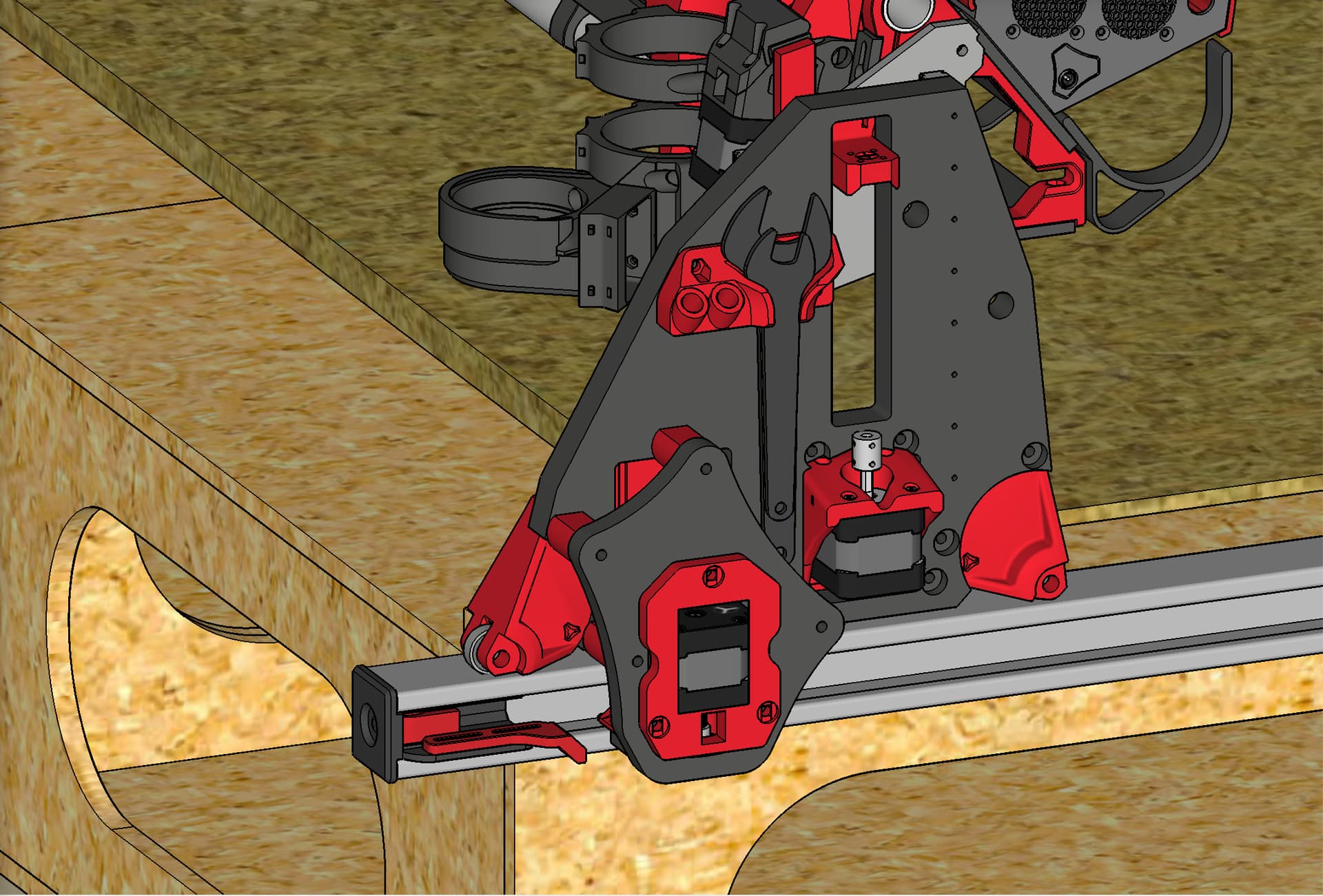
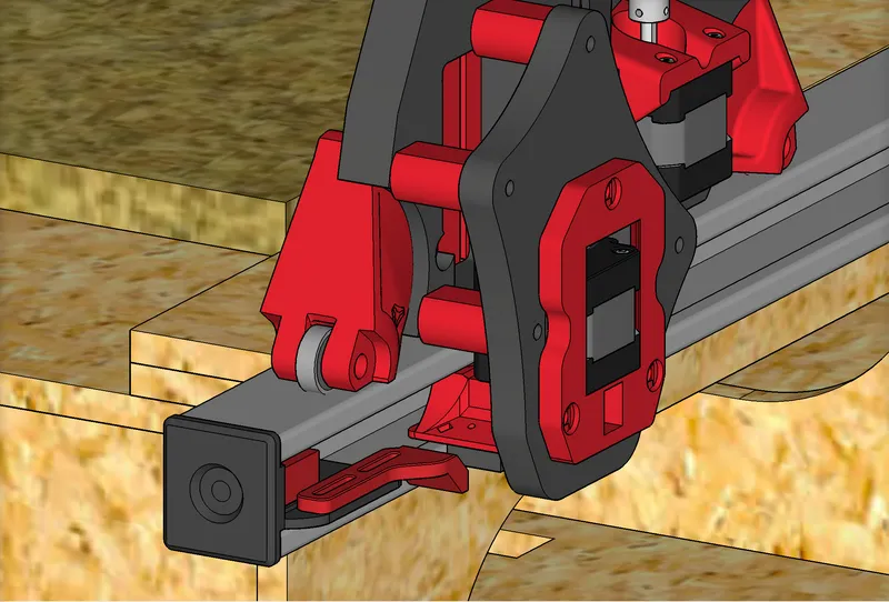
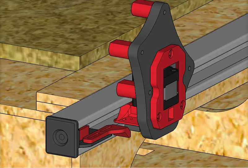
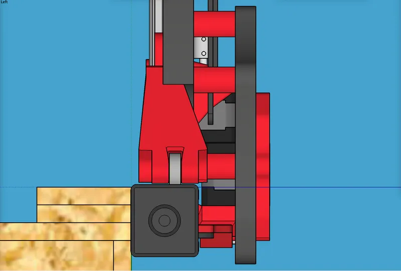
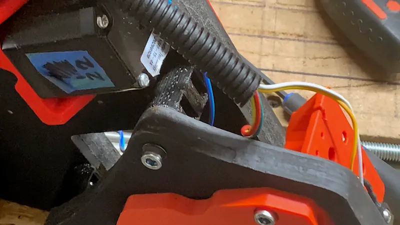
- Study the images below for how close my LR3’s 608 bearing “wheels” ride near the edge of the metal strut. If your LR3 rides further from the edge than mine, you will need to remix the standoffs to make them longer, by about the same difference.
- Prepare the four (4) printed “standoffs” by inserting M5 nylock nuts into both capture slots on each standoff.
- Attach the standoffs. Most of the connections will use M5 x 25mm, but some may need M5 x 20mm. It is strongly recommended you tighten these screws by hand, not by a drill. If you get a screw cross-threaded into a captured nut, then that part is probably toast!
- On the side where the standoffs mount on the existing YZ plate:
- Screws go in from the inside of the YZ plate, and out into the standoff, into the captured nut inside it.
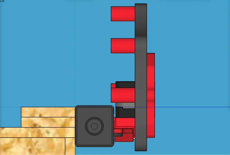
- The top standoff mounts in the old hole that used to hold the old Y motor mount at the top. (The bottom two old holes will be used to secure a printed cover so the old opening is not a way for chips/dust to come through.)
- The next standoff down and to the left mounts in a hole that is shared by the front printed “wheel well” part that holds the 608 bearing “wheel.” It’s the upper of the two screw holes holding that printed part on.
- The next standoff down and to the right mounts in a hole that is shared by the existing Z motor mount. It’s the left of the two (if your LR3 is oriented like mine).
- The next standoff down and to the left mounts in a hole that is shared by the front printed “wheel well” part that holds the 608 bearing “wheel.” It’s the lower of the two screw holes holding that printed part on.
- In above the above mentioned second, third, and fourth standoffs, you’ll need to loosen the existing screws, remove the old nut, and then reinsert the old screw into the new standoff with its new nut.
- NOTE: if you think you will have trouble getting the long belt threaded through the pulleys later, thread it through now, while the new Y-extend plate is not yet installed!
- On the side where the new Y-extend plate mounts onto the standoffs, you’d simply align the new secondary Y plate with the standoffs, and screw in to mount it. I suggest tightening them in turns a little at a time.
- On the side where the standoffs mount on the existing YZ plate:
- TENSIONERS
- PLEASE NOTE: to provide for print quality, the end caps are designed to print with a one-layer thick sacrifice layer across the M5 screw hole in the center of the end cap (facing out the end once installed). After the parts are printed, remove that one-layer covering over the screw hole either by burning it out with a soldering iron, or cutting it out with a knife, or drilling it out.
- PREPARE THE “Tensioner Endcaps” x2
- Using two (2) M5 x 45mm screws, insert one screw into each of the two “Tensioner Endcap” parts, from the outside toward the inside. These will pull the printed “Tensioner Belt Clip” part to tension the belt.
- Using four (4) M3 x 12mm screws and M3 nylock nuts (two per side) mount the “Adjustable End Stop” parts onto the corresponding “Tensioner Endcap” parts.
- PREPARE THE “Tensioner Belt Clips” x2
- Using two (2) M5 nylock nuts, insert one into the capture slot in each of the “Tensioner Belt Clips.”
- One possible approach for keeping the nuts straight and aligned is to drive an M5 screw in from the outside, and get it threaded a bit into the nut in the entrance to the slot, and then use the screw to “pull” the nut into position, and once it’s seated, remove the screw. You want the screw seated and in the right alignment. Cross-threading ruins parts.
- Using two (2) M5 nylock nuts, insert one into the capture slot in each of the “Tensioner Belt Clips.”
- RE-INSTALL the long near-side BELT
- If you have not already done so, thread the long belt through the assembled Y drive mount and pulley system, which is to have already been assembled and installed. This is like you did for the original LR3 build. If you have trouble, you may need to remove the gantry and flip it over to get better access.
- Once the belt is through the pulleys properly, then thread the long belt’s ends through the “loop” in each of the “Tensioner Belt Clips.”
- Once the belt is secured, slide each “Tensioner Belt Clip” into its corresponding “Tensioner Endcap” and push the belt clip like a “slider” while turning (tightening) the M5 screw of the “Tensioner Endcap.” When the screw catches in the threads of the nylock nut, you will be able to tension the belt by tightening, loosen by reversing the screw, and remove the belt entirely by reversing the screw far enough. I find using a drill for this is handy.
- ADJUST THE “Adjustable End Stops”
- As needed so that these stops are positioned parallel to your existing Y end stops on the far side, loosen the nuts, slide the part back or forth, and tighten when good.
- It is strongly suggested that you redo your squaring process. You now have two ways to adjust for being square: GCode commands and physically adjusting these end stops to match the far side.
- CHECK AND VERIFY
- that there is absolutely no contact between the new Y mount and the metal strut at any point along the axis. This is important. Contact is potentially bad. Even if it seems to “brush” and glide along the lip of the metal strut, during a long cut job when heat builds up, it could become an issue. You want a buffer of empty space above and below the “business end” of the new Y mount and the lips of the metal strut.
- INSTALL the Y Drive COVER
- Install the printed Y Drive COVER over the old slot. This is a cover for the opening remaining in the stock YZ plate. Use two M5 screws and M5 nuts, inserting them into the two bottom holes of the holes that formerly held the old Y motor mount.
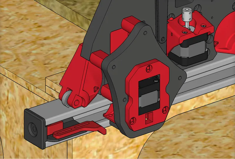

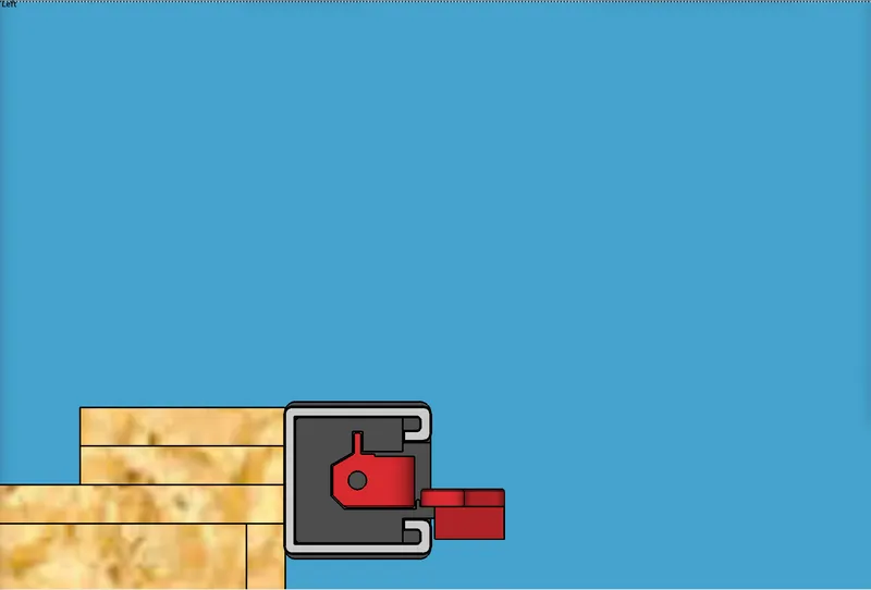
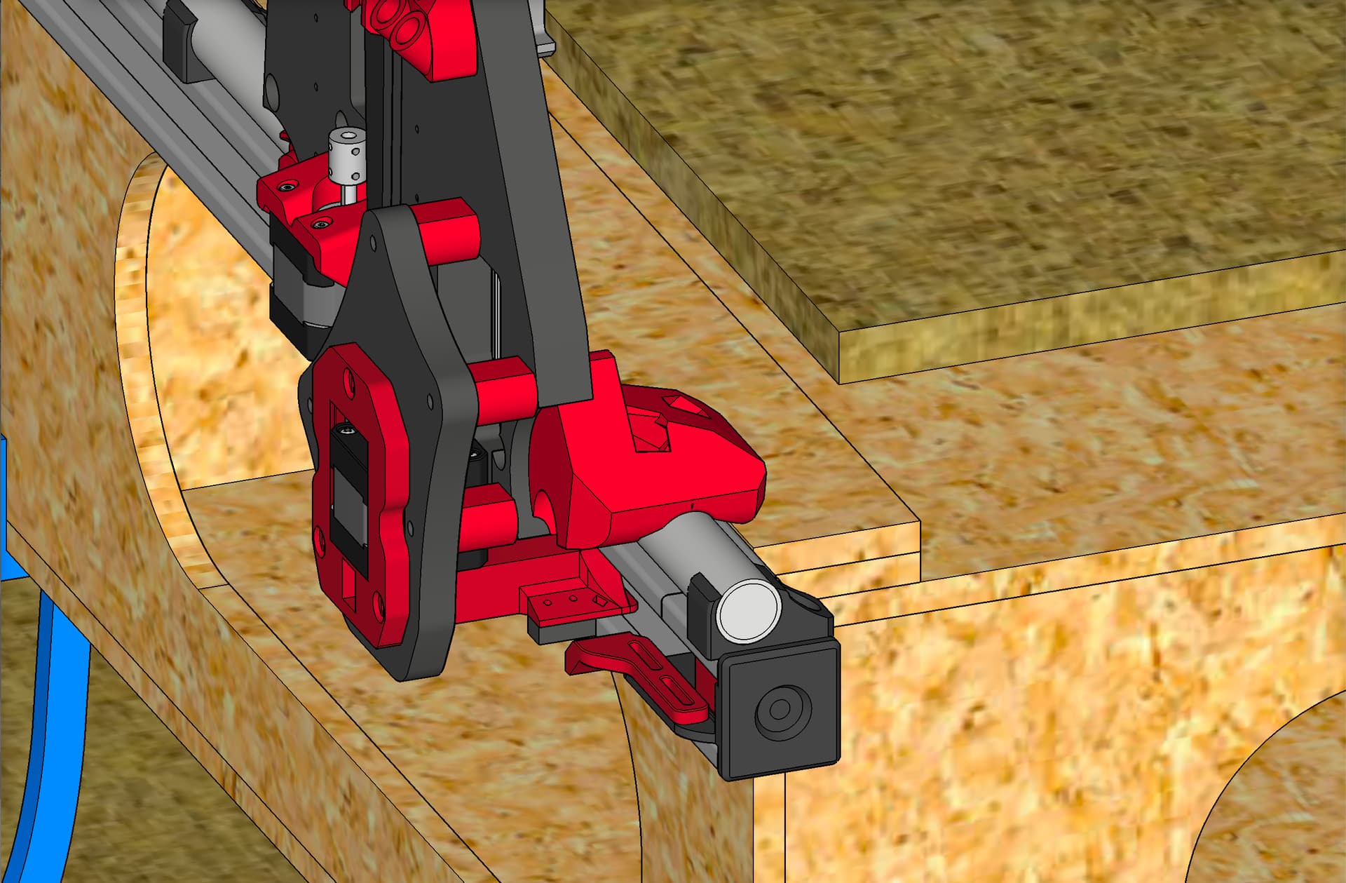
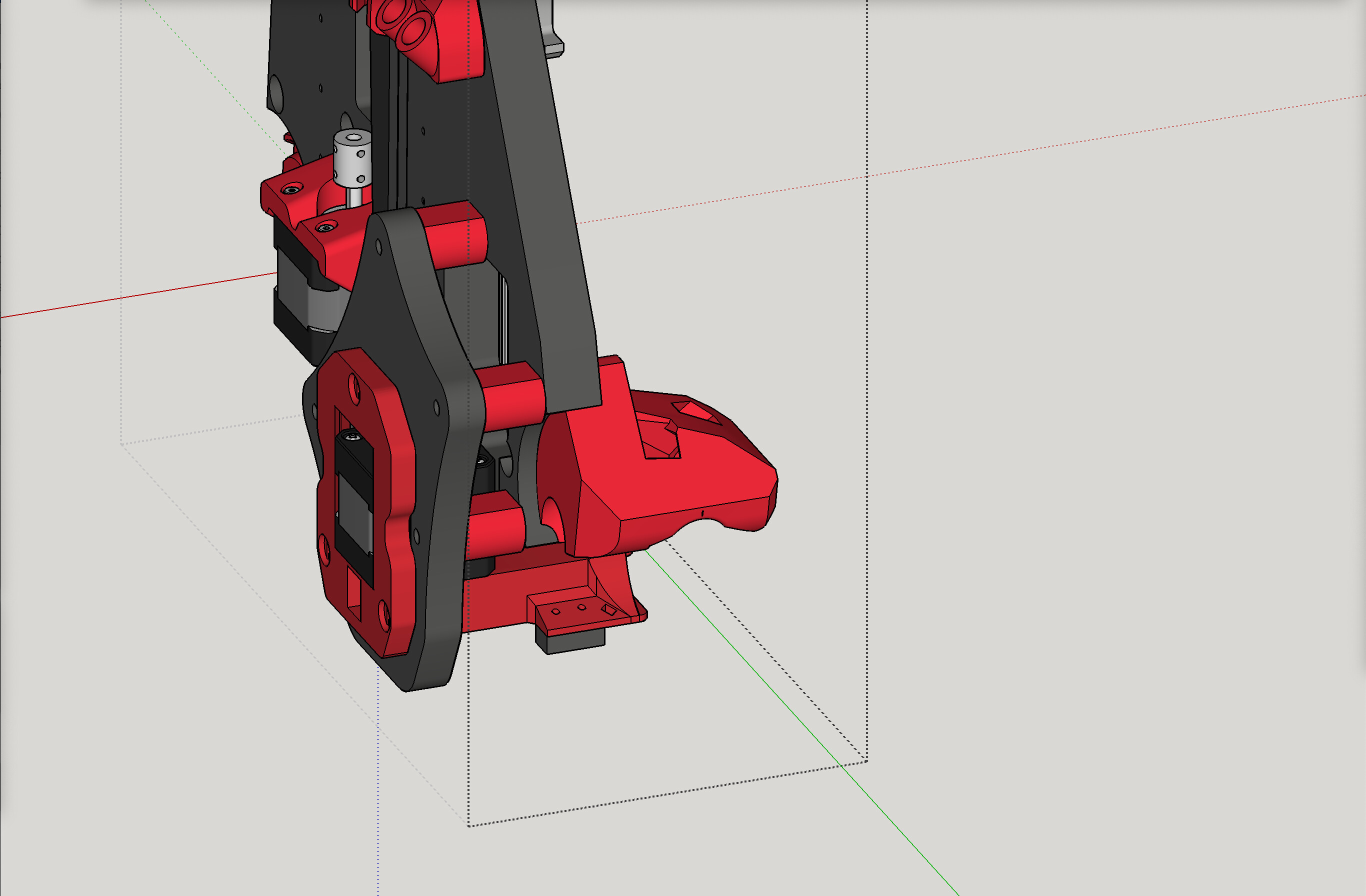
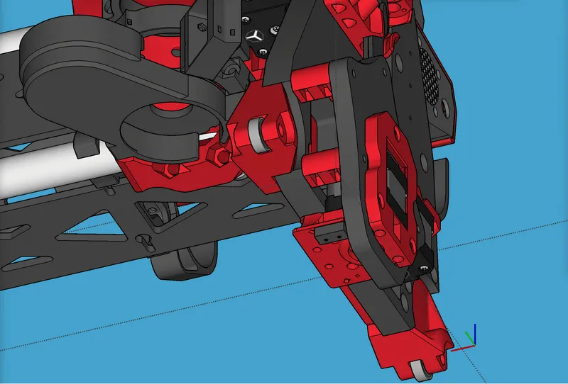
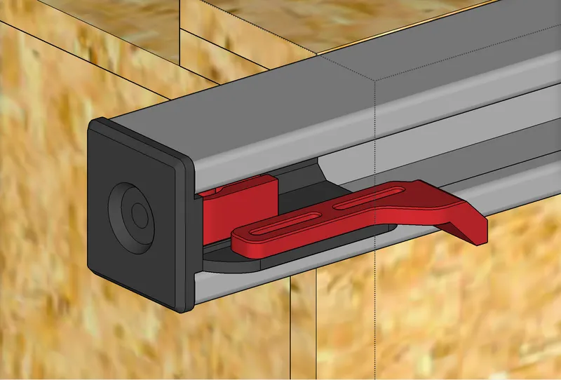
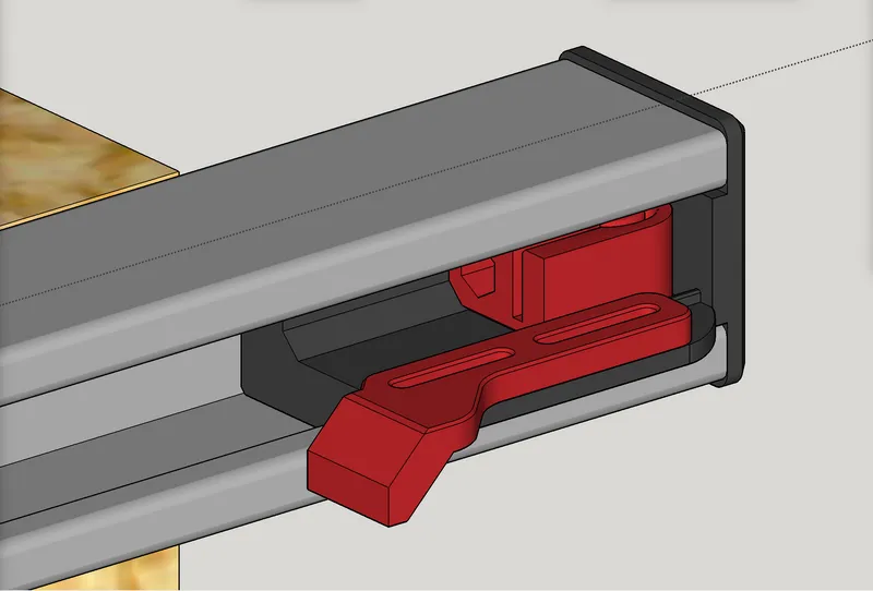
Below: Underside view (installed system from underneath):
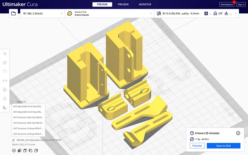
Below: The printed parts that make up the end caps / end stops / belt tensioners (both sets), shown in Cura, with print time using 0.6 mm nozzle, 0.3 mm layer height, 3walls, 30% infill.
PLEASE NOTE: to increase print quality, the end caps are designed to print with a one-layer thick sacrifice layer across the screw hole in the center of the end (facing down in the print setup below). After the parts are printed, remove that one-layer covering over the screw hole either by burning with a soldering iron, or cutting with a knife, or drilling it out.
Below: The printed part named “Y Drive NEW.stl” needs some supports, but see below how I used support blockers in Cura to constrain the supports to only limited areas of need, saving on print time (same print settings as mentioned above):
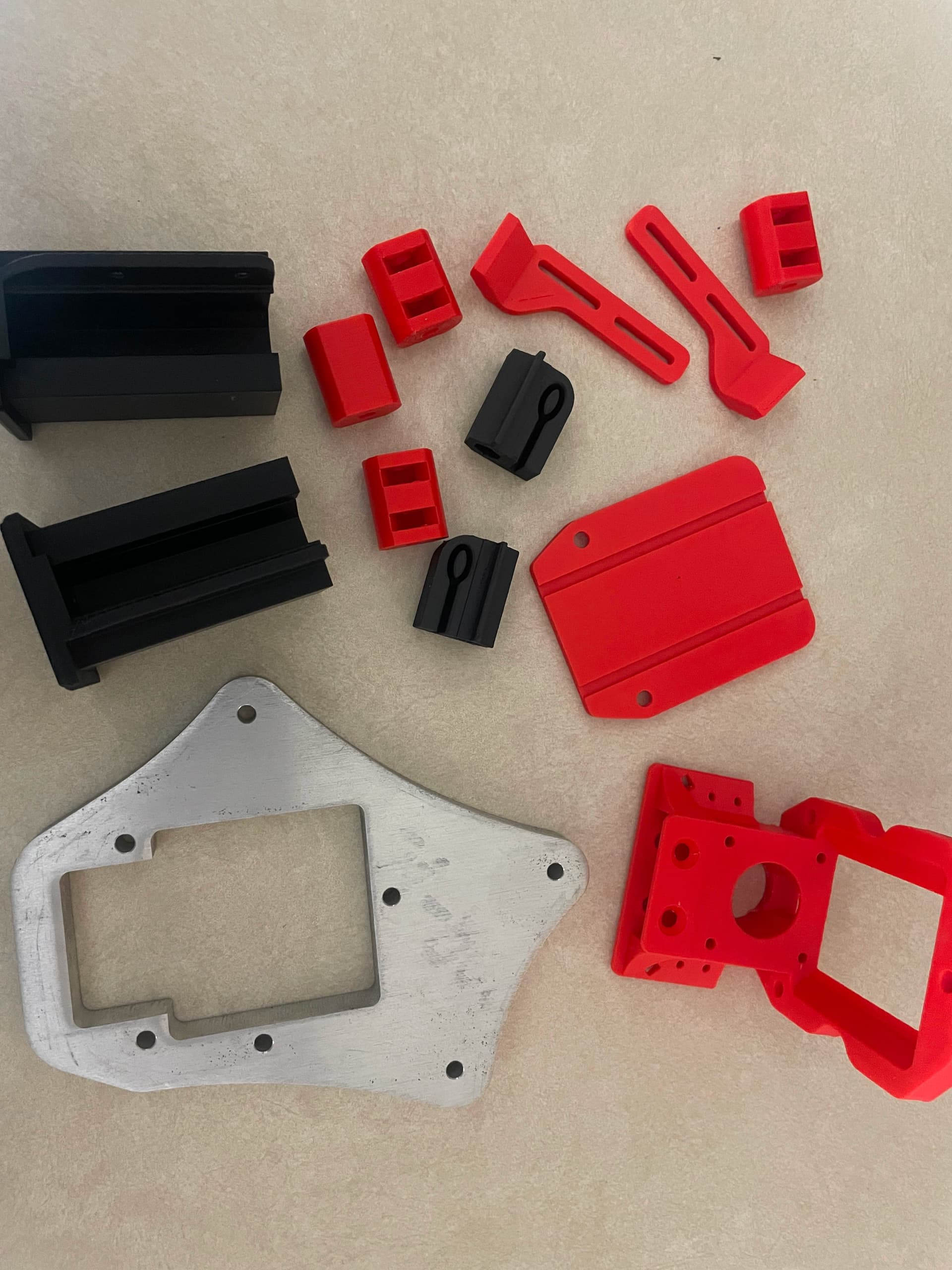
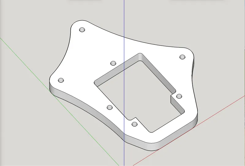
Below: the new “Y-extend Plate” which is ideally CNC cut out of ½" MDF or ½" plywood, but can also be 3D printed. The files include two SVG files: one is a 1-up for ½" MDF or ½" plywood, the other is a 2-up for ¼" MDF or ¼" plywood, of which the two can be glued and clamped together to form one ½" plate. STL is provided in case you choose to print.
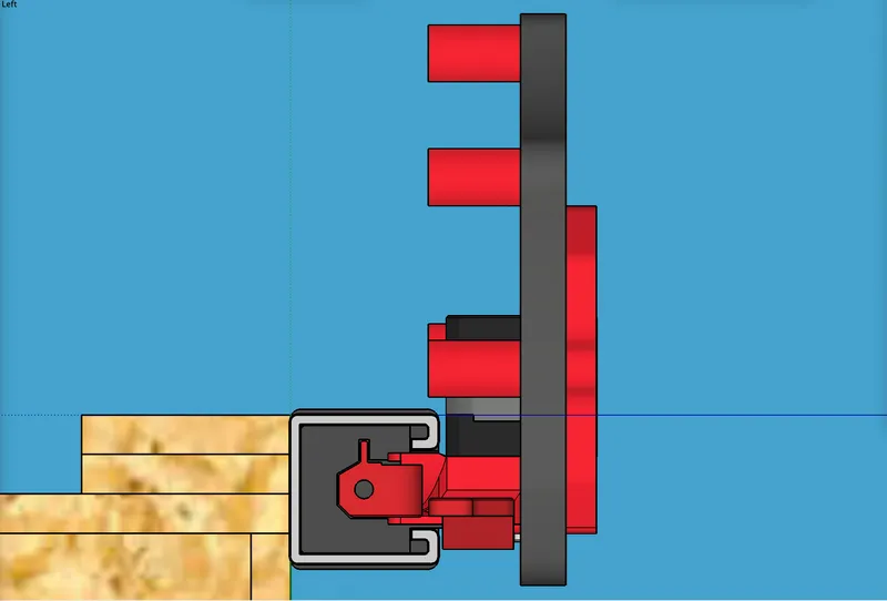
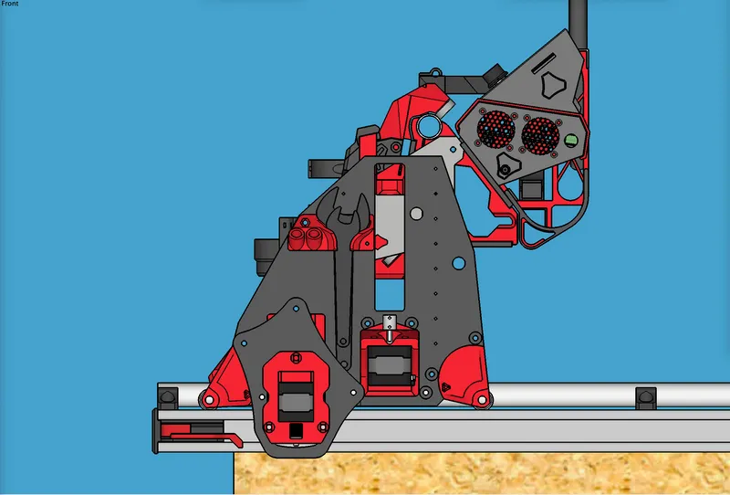
Below: Use tapered bore M5 x 20 screws (not 25mm, as it sticks out too far):
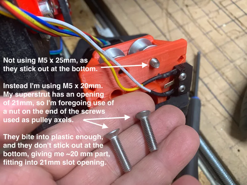
Below: Use tapered bore M5 x 20 mm (not 25mm as it sticks out too far):
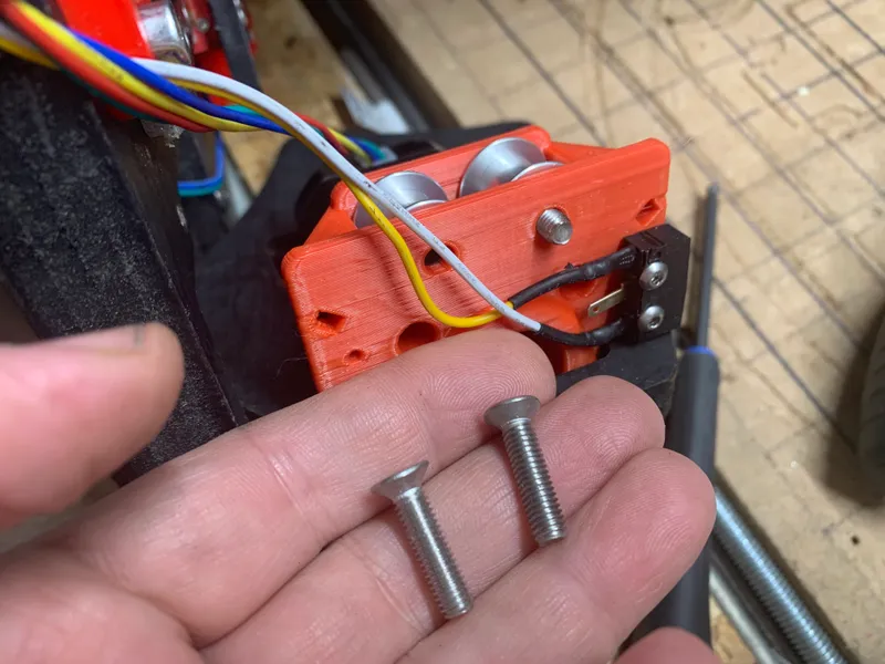
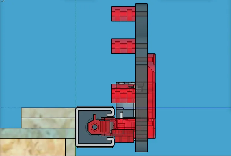
Below: Showing inserted M5 x 20mm tapered bore screws, no extra stick out.
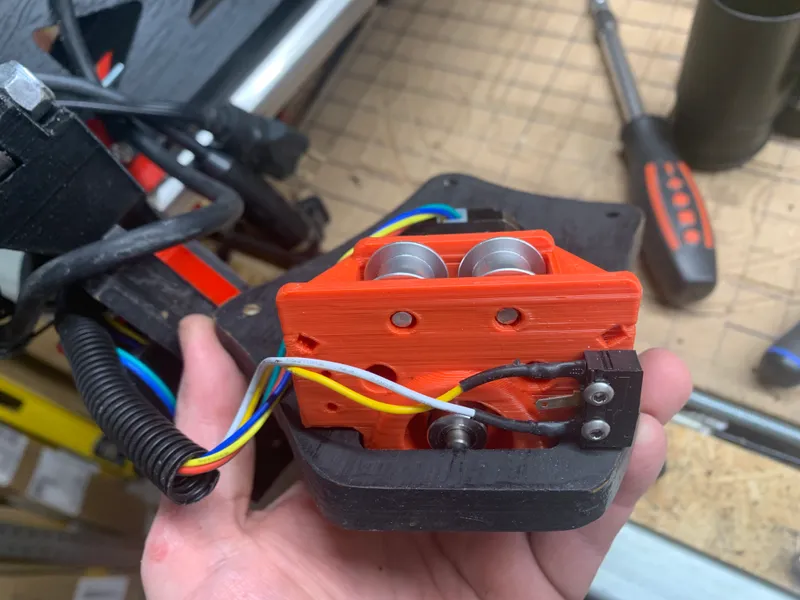
Below: Showing inserted M5 x 20mm tapered bore screws, no extra stick out.
Below: Showing inserted M5 x 20mm tapered bore screws, no extra stick out.
Below: On the printed “standoffs,” use M5 screws, either x20mm or x25mm as needed. I tried M5x20mm on standoffs, but settled on M5x25mm in most cases. Use M5 nylock nuts inside the printed standoffs (there are capture slots). Remix the standoffs if you need to adjust due to your LowRider’s distance from edge of superstrut being different from mine.
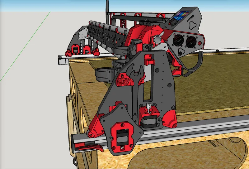
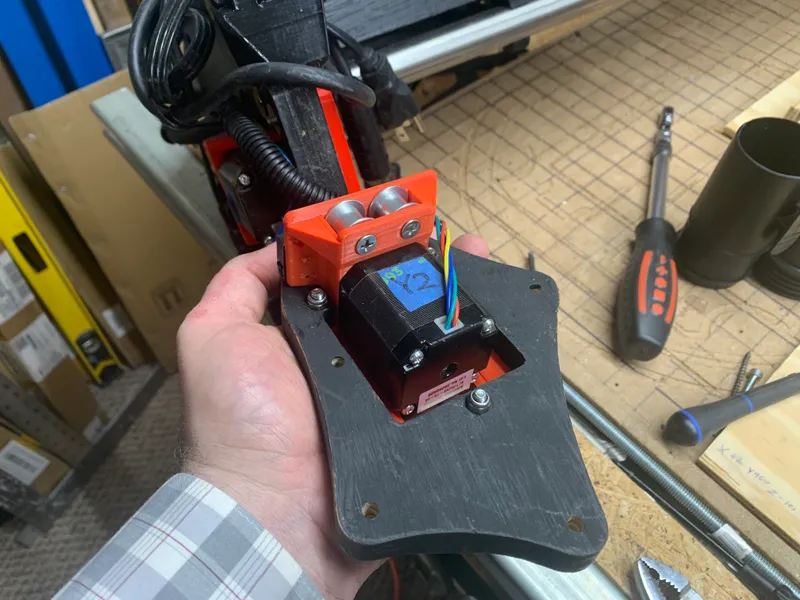
In the pic below, all the standoffs are installed, and the secondary Y plate has been installed onto them (note that my LR3 gantry is flipped over here, past halfway toward upside down):
Below: All standoffs are on and the secondary Y plate is installed onto them (note that my LR3 gantry is flipped over here, past halfway toward upside down):
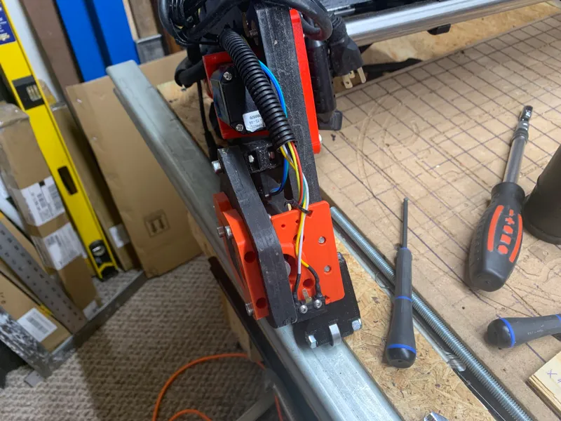
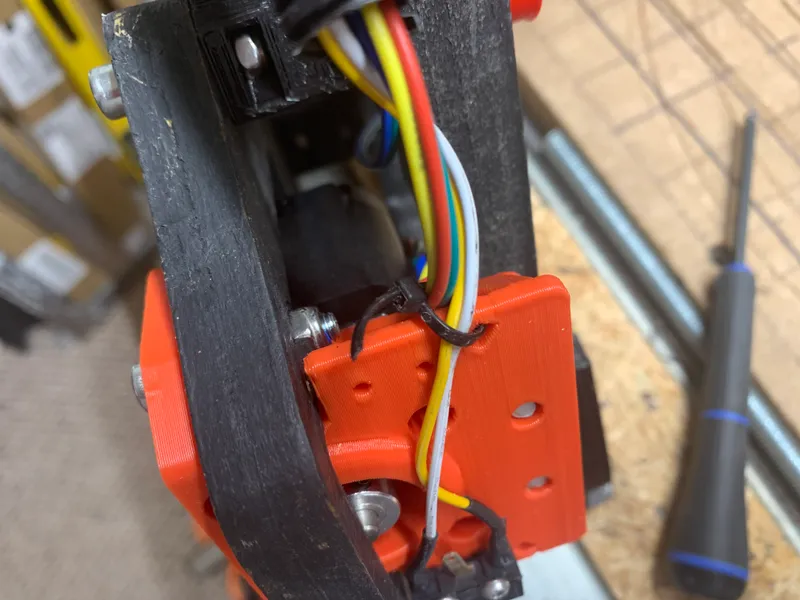
Below: Making use of zip tie port on new Y drive motor mount.
Below: End stop update notes, and illustrations:
- I originally built the end stops into the end caps/inserts as a single part for each end, but that lacked adjustability for the end stops, so I redesigned to separate the end stop from the end cap, and with adjustment slots for the end stop to be attached onto the end cap. This is working great for a physically adjustable end stop.
Change log:
- March 13, 2023 - Original remix uploaded. Labelled as v1.0.
My PayPal tip jar: https://paypal.me/design8studio
Various LowRider 3 CNC remixes:
View all my models and remixes on Printables:
*Amazon product links are affiliate links.