NEW IDEA — for LR3's with superstrut — long belt (usually Y) housed *inside* the strut

A couple of things are worth mentioning :

  • The superstrut can vary slightly in the span across its opening. For most of it, the measurement was north of 22mm, although occasionally it measured less than 22, and in a couple of places barely over 21mm. (It’s not a precision machined product.) So I designed for it as though it were “21mm or even less” — and targeted the bare minimum height in which I could accomplish a design of a functional part, which seems to be 20 mm, and that is only achievable by not putting nuts on the ends of the screws that serve as axels for the pulleys, and by countersinking the heads of those same screws into the printed part. Lest anyone think that the axel screws could accidentally come out during a job: there is a lip of steel of the superstrut riding just above the heads of those screws, so they literally cannot come out during operation.

  • If you do this mod, trust me when I say that you will want an air gap between the “business end” of the new Y Drive mount and the upper lip and lower lip of the superstrut, at all places in the range of motion. While I was working with an early prototype in which the portion of the printed part (with the pulleys in it) was a bit taller, there was a slight contact — a faint brushing of the Y drive mount against the smooth lip of the superstrut. Instead of immediately redesigning the print part, I did some testing, and found that the slight contact eventually increased to a more firm “friction interference” type contact during operational testing. My theory is that the warmth of the stepper motor may have caused the plastic to expand slightly. Whatever the cause, the result was that a “braking effect” of the contact became an issue that could not be ignored. I redesigned the part to go from “almost as short” as 20mm to actually being 20mm. That gave me a smooth ride with air gaps at top and bottom, throughout the full range of motion, and I have been able to successfully complete multiple, multiple full “torture test” type work jobs flawlessly.

  • My recommendation for testing regarding clearance is to set up some “torture test” type work jobs, and cycle through them (at first) with no power to the router, and no bit actually making any cut contact with the material, and no dust collection noise, and listen for “the sounds of silence.” Ideally you should hear nothing but the stepper motors. If you hear any faint sound of plastic of the Y drive mount sliding along the steel of the superstrut, then it’s making contact somewhere, and your positioning / alignment need corrected. Also, visually inspect it carefully during the full range of motion. You want this thing to have no risk of its movement efforts becoming like stirring peanut butter with a spatula (because of some heat expansion or whatever). You don’t want it “sliding” — you want it “gliding” in air. Its motion should be effortless.

1 Like

This is working flawlessly over the course of many, many cut jobs. I’m super super pleased. It’s exactly what I was hoping for!

2 Likes

I will be making the files for this available publicly soon. I had given early access to my Patreon supporters. However, I later made an administrative decision to delete my Patreon. The files will soon be available for download from my Printables page here.

@DougJoseph
Are you still considering releasing these designs since you’ve retired your Patreon account?
I’m not quite ready to start the rebuild but it’s getting closer with most parts printed.
Would buying you a ko-fi encourage an early release :slight_smile:

1 Like

yes, still planning to release. I’ve been trying to balance obligation to the patrons from before I retired the account with the desire to go ahead and release. Any and all kindnesses shown re. cookies and ko-fi are always appreciated. :slight_smile:

@Darwin: OK, I got the mod (that was mentioned above) posted on Printables!

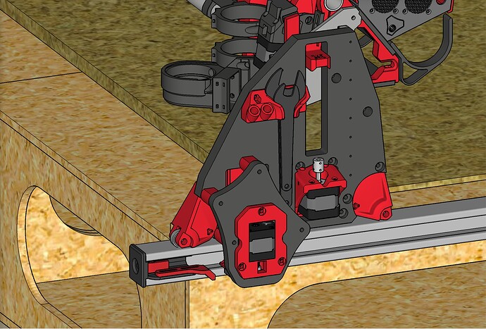
LowRider 3 CNC mod: HIDE / PROTECT one of the Y AXIS BELTS inside metal strut / unistrut / superstrut) (v1.0)

https://www.printables.com/model/422468-lowrider-3-cnc-mod-hide-protect-one-of-the-y-axis-

Thanks for this Doug!
I read through the printables notes. I think I may try without the strut. Use a slight table overhang and possibly box it on the bottom. Should simplify alignment too as the opening will be bigger but I’ll have to see what belt parts need rejigged.

1 Like

Sounds good. The existing stock LR3 belt holders/tensioners get completely replaced in this mod, when used with metal strut as shown.

One option would be to remix the “endcap” for side mounting or top mounting. Another idea would be a remix of my “table extender” mod, or some combo that lands you at the right place.

1 Like

Good morning Doug,
trying to manufacture the Y-extend Plate using Al .5" but run into several problems with skp file. First, don’t have SkethUp, so extra difficult. We are using FS360. Online conversion from skp to dxf generates a lot of nodes on the profile instead of smooth arcs. These nodes act like starting and stopping points for our tool during cutting, and rather than cutting along a smooth path, this will cause an effect that looks similar to “chatter” when machining the part. Can you help? May be STEP file or a clean DXF and you will make my day :slight_smile:

Hey! Glad to hear you are making this. Wouldn’t the SVG I provided in the Printables listing work? Or at least be something you could use to convert to DXF?

Thanks, Doug!
Yes, this is where I started yesterday.
The problem is the SVG is formed with a lot of arc, creating the chatter. I attached the FS360 view below.


Y-extend Plate STL - Chatter
Any ideas will be welcome.
Thanks!

Did you try trochoidal milling? This looks rather a problem with the CNC than with the CAD.

CAD problem. By The way, using CO2 laser for cutting this and the chatter creates an on/off laser. If I was using wood then it would not really matter.
Thanks, Philipp.

Having many small segments like that shouldn’t cause the laser to turn on and off repeatedly.

Anyway, if you have Fusion, tracing that design with all of those reference points shouldn’t take more than 5-10 minutes and you’d have a clean arcs to cut with

@jcassar :
Although I wish I could agree with @Michael_Melancon that having multiple small straight segments instead of an arc should not cause a laser to “pause” ever so briefly at each change of segment, I have run into this myself on my CO2 laser, using Lightburn with a RUIDA controller. The little “pause” at each segment causes an extra bit of “burn” where each segment meets another. Very annoying.

In googling just now to see if there might be a software solution, in my case I use Lightburn so I was looking there, I found a mention here:

…about a Lightburn specific feature called “Auto-join selected shapes” or some such. It might well solve the problem for Lightburn.

However, in your messages, you indicated “We are using FS360” — which is to say, your CAM is being done there. In my instance, the CAM is being done in Lightburn. I say this to mention that while you later indicated you think it is a CAD problem, it may well have a CAM solution, and it would likely be a CAM outputting option, or Post Processor CAM option (regarding treatment of segments that could/should be treated as arcs).

PS: Be aware that in SketchUp, modeling is essentially an easy way to “mesh edit” (perhaps what Fusion refers to as direct editing of a mesh), then any arcs or circles created in SketchUp require a choice of “how many segments” in advance (or else the default number is invoked) and the result is a group of straight line segments arranged to look like an arc in the overall “mesh.” So, because of this, having the original source SketchUp file would probably not help you.

@jcassar :

The main reason I think there is a CAM solution on the Lightburn side is that, while I have not personally confirmed it, I found the above post by way of this one:

…In which the OP seems to have marked the other thread (linked above) as the “Solution.”

Also note, that when importing a mesh (i.e. STL file) into Fusion 360, there is a way to convert it to a solid body that seeks to arrive and what could be “built” in Fusion 360 by way of its built-in “base” modeling tools. This could result in a body that would ouput in F360’s CAM options without the chatter.

There are YouTube videos about how to create bodies in that way.

Now, two days, and still not done, so not so easy. The Net is full of articles talking about this, but no join lines feature. Looks like this:


These nodes act like starting and stopping points for our laser during cutting, and rather than cutting along a smooth path, this will cause an effect that looks similar to “chatter” when machining the part.

Well, he said “on/off”. I can understand a “pause” as I’ve seen that happen plenty of times for different reasons with successive commands being processed, but switching the laser on and off is a different behavior

True, I missed that distinction. Off and pause are different. Even a pause would be a problem in cutting.

That looks like you just extruded the SVG directly. You have to create a new sketch and use the reference points to redraw it so you have proper geometry

The number of points that are there make it pretty easy to redraw the model on top. The extrusion will then not have all the breaks.

1 Like