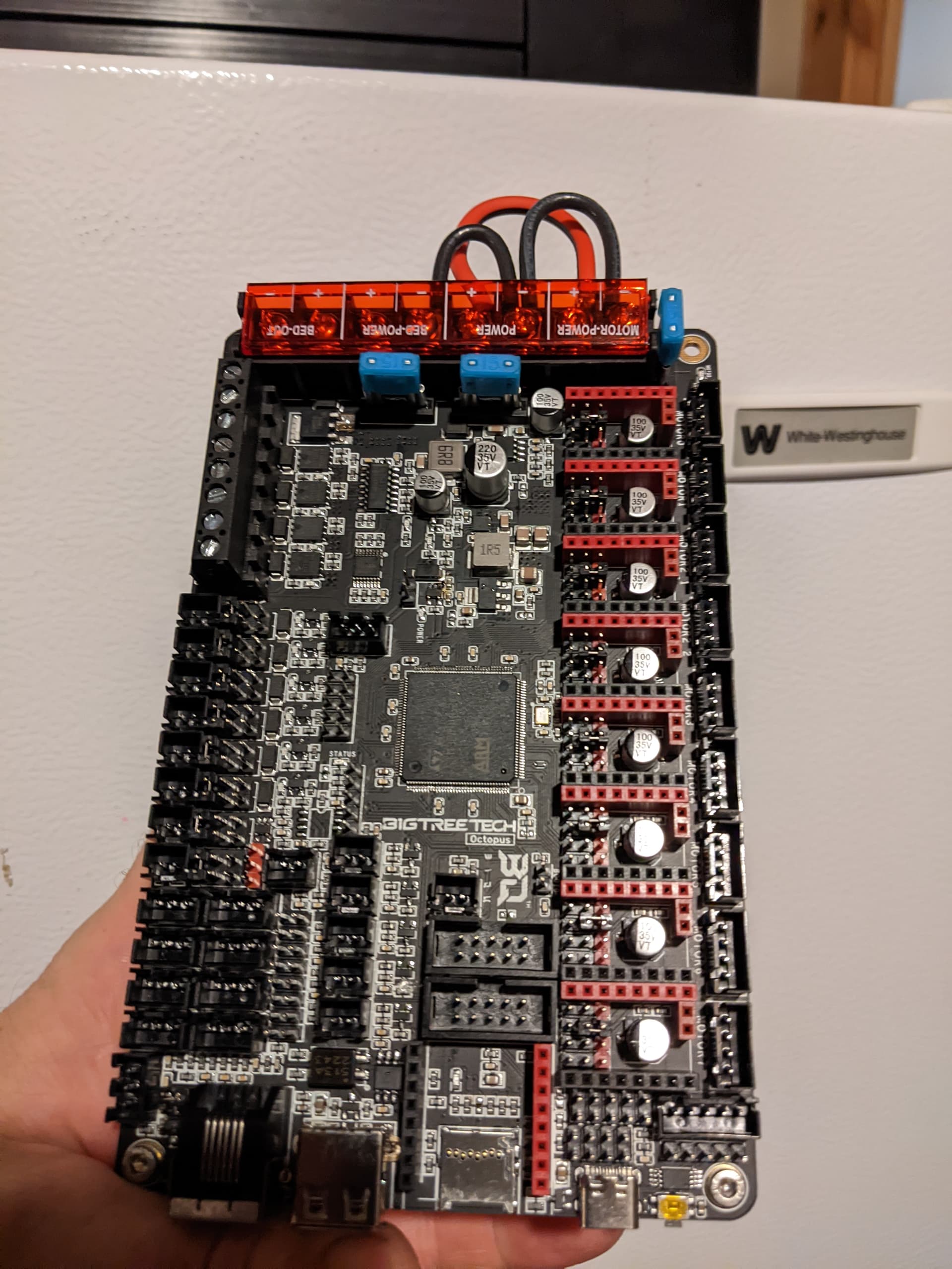
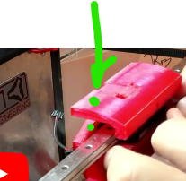
there are two blue fuses horizontal in the picture. below the right one is a capacitor and below that is a vertical surface mount cap and below that is a square silver box (1R5). Not sure if that is an inductor, but it smoked. the arc came from the 2209 closest to the usb at the bottom and before I could power it off, it popped and smoked.
I’m not really happy with my BQ luck right now. As it stands, only 1 of the three boards I’ve gotten from them is functional. My SKR on the primo is chugging along. The E3V3 upgrade for my ender is bricked and this octopus is toast. Plus the brand new SD card that was in this board fried as well.
I jumpered the board as outlined in the voron documentation since its setup is going to be only slightly different than the voron.
It was late last night, there were too many things plugged in to start with and I needed a $60 piece of humble pie. I will encourage all to go slow and do one thing at a time… even if you’ve done this a few times before.
I.am generally very careful with my wiring… but not super neat.
My MP3DP v3 is still a bit of a mess. Not quite “rat’s nest” but not where I’d really like. I tend to stop when things work.
My v4 is … well not much better. I tried to do a little better with the initial design, so it has some nice wire runs, but once again, once it all works…
What a bummer to see that the Octopus board was damaged.
You’re off to a good start of the build and I’m watching with interest.
I should elaborate a bit on the whole organized vs rats nest thing. It’s my nature to want to just hook things up quickly and test- just as you did. That has never served me great either, and as I’ve gone along I’ve spent a lot of forcing myself to slow down, clean up, organize, route better, etc. That has served me well at work and the things I’ve worked on over the last few decades have gone up in value by about 6 orders of magnitude. So I tend to over do it. That’s got a lot of down sides as well.
It means I tend to stall out and take a long time building things and I have no shortage of unfinished projects and stopped or abandoned plans. That’s not great, either.
I get both sides of the “Perfect is the enemy of good enough” debate.
I’m really curious about what happened to that Octopus board. Mostly since it seems there is a lot of boards getting fried, and though it isn’t possible to protect against every mistake it does strike me that there is way too little protection in these boards for things that could be made less likely to get toasted
It seems the most common failure is hooking up an endstop wrong, or a user hot-mating or hot de-mating a connector while the board is powered. Just thinking out loud what could be done to make that less likely or less damaging.
When I used to host 3d printer help days at the local makerspace, it was amazing to me how often I’d see severely smoked boards. That’s only partly the users’ fault. I suppose there isn’t much downside for the low end board manufacturers to skimp on protective features because every smoked board is a fresh new sale.
To pop two fuses and arc a 2209 is a pretty significant event. Do you have any other recollection of what may have gone wrong?
(Edited to change SKR to Octopus, since that’s what the board is)
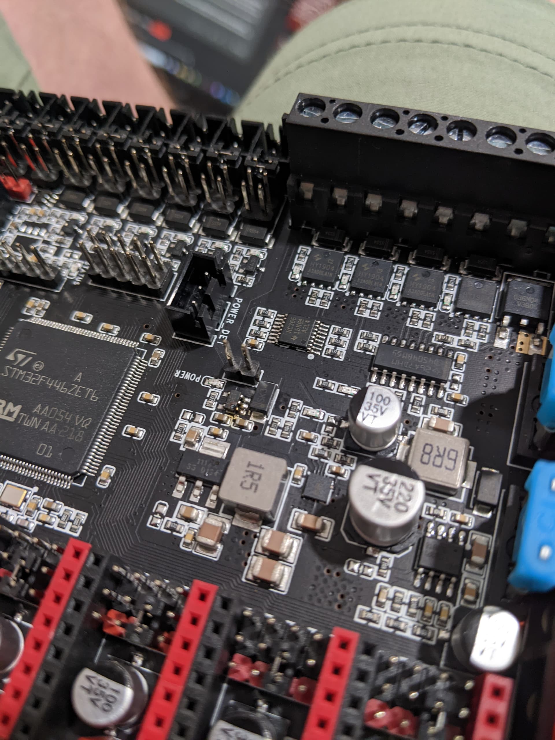
That 1R5 should be a 1.5 Ohm SMT inductor.
To the left of that I see two voltage regulators that appear to be blown.
I don’t see any obvious sign of a sustained arc or short on the 2209 socket by the USB. What did the driver itself look like?
My uninformed guess would be an a power rail got shorted to ground- maybe with an endstop.
off it would have been wise to flash the board with only power and nothing else but the SD card.
I set all jumpers according to the voron 2.4 docs for the octopus. Their diagram showed red boxes for which to remove and green boxes for which to add for the 2209 setup. I did bend the one pin similar to the SKR pro on the MPCNC and that needs to be bend back, but not a showstopper
all 5 steppers were plugged in and all 8 of the 2209’s were on the board though only 6 were required. The wiring connectors both ends of each of the 3 z motor wires were custom crimped by the author and it is possible a wire strand was missed and one of them shorted. Probably not the most likely scenario to cause what occurred.
No heater coil wires were plugged in because voron docs said don’t until after you have your config set, but the bed heater SSR digital side was connected
the extruder hot end fan was connected.
both the bed thermal sensor and the hot end thermal sensor were wired in.
I did have one end stop plugged in, now that you mentioned the end stops… I had it wired like the MPCNC. I should have doulbe checked that and I bet that is the issue right there. Are the end stops supposed to be NC or NO. On the MPCNC, they are NC… that could very likely be the issue.
On the octopus 1.1 schematic that matches the board layout (446 processor), the part that smoked is L9.
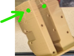
You mention 2 parts that appear to be blown. I’ve taken a better photo for review. How would I get replacements for those… mouser? do I need a hot air rework station or will my old weller be able to do it?
If that were my board and I was going to try and fix it, I might try to pull the smoked parts by heating up the pads on the components and using a pair of small side cutters to help free them up up. It’s already dead, so just taking care to not overheat and lift a pad is most important. I’d be willing to cut up a part as long as I could cleanly get the lead de-soldered from the pad.
I’d try to clean it up with some solder braid, re-tin the pads, then solder down the replacements. None of those look like they have to be hot air rework.
Mostly, that’s about how good your detail work is and whether that old weller has a suitable tip.
You probably can buy the parts from Mouser or Digikey, though they might be a little spendy for single unit purchases.
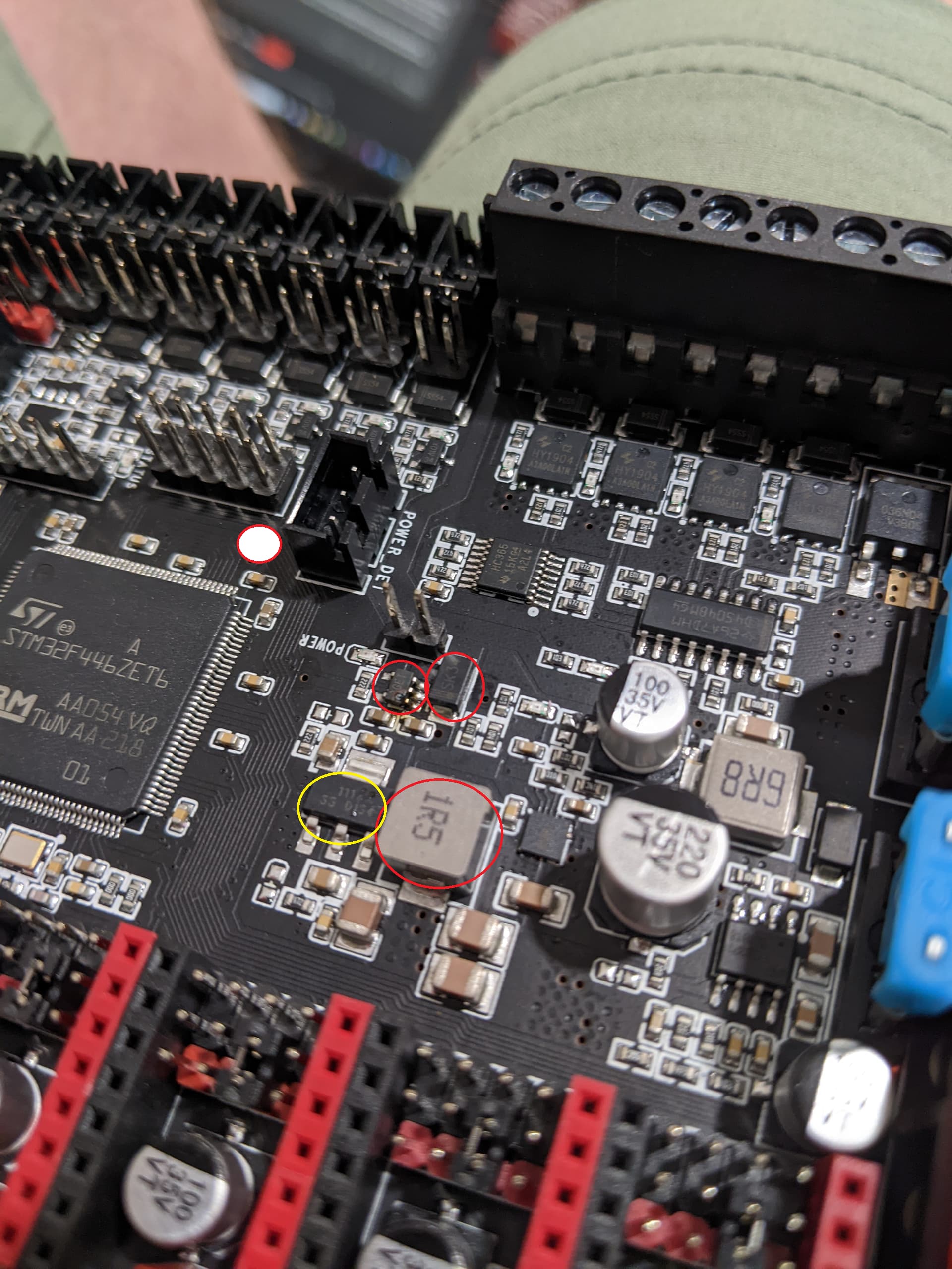
Edit: There’s a red ellipse with a white infill that is a fat finger on my part. Only the three red with transparency are real.
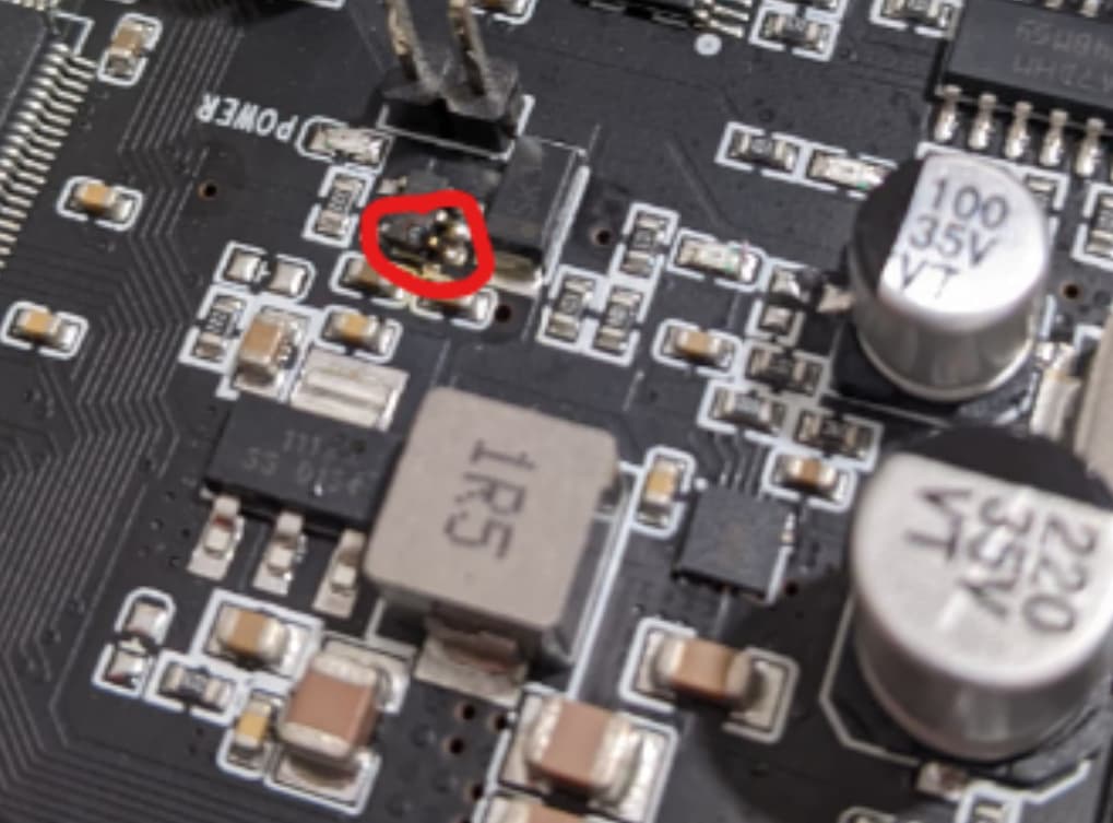
Edit2: You said above that the 1R5 component smoked. If you saw it smoke I’d replace it. Possibly you saw the neighbors light up, in which case it may not have smoked. To the left of that in the yellow circle I see a hint of what could be thermal damage, but it isn’t at all certain.
Edit3: Regarding the endstop- the most common failure is to get “off by one” pin and install the connector between ground and the adjacent voltage pin. In my opinion, this is a STUPID design implementation. The connector should be keyed or have a jumper and a dummy pin to prevent accidentally plugging in an enstop across those points. Dumb, dumb, dumb design. If I’m right about the enstop, that’s what happened.
Anybody have a klipper printer.cfg for the octopus they would be willing to share? The last few days of searching on and off has only shown various specific segments. I was going to just pull the voron config and modify from there, but figured I would ask in the hope it might save some time.
Non stock parts on my build are shared in mp3dp-v4/mods, absolute $h1t show of a mess, includes prototypes and abandoned experiments, but everything’s shared. Am trying to share final parts used on my build via a MP3DP v4 Printables Collection, which also includes parts designed by other V1E community members. However, I haven’t bothered to publish some parts yet that are still lurking in the /mods folder. One day…
So I have the new parts and I have not rewired and tried again now being a bit gun shy what with the last disaster.
How do you all decide how to lay out the wiring in your control boxes? I have access to 3d printing, CO2 laser cutting, acrylic, wood, etc, but so far my best box is still a hack job. What design considerations are paramount for a good electrical enclosure /control box.
In the box I will have:
Skr octopus
Ssr
5v stepdown regulator
24V power supply (meanwell style)
I’ll be running klipper on a raspberry pi with 7" touch screen, so in addition to stepper wiring and hot end and bed wiring. There will be a USB cable and power to the rpi (any idea how to convince the raspberry pi that my 13 a 5v regulator is actually 5v? And not in danger of browning out?).
New parts have been here a while and I have been steadily rewiring. The A motor (right side) belt has to be replaced because the carriage has no space to hold excess belt, which led to cutting it too short and it was way too tight. New length of belt came (thanks @vicious1). I had previously cut it about 1/2" too short and I believe I’m not the first one to do this.
My latest question: how tight should the belt be when initially connecting it and how tight should it be after using the tensioner?
I will put in my request to have the belt button wrap knob thingy in the carriage that the belt can fold around to interlock on itself and extra belt can stick back out along the incoming belt path (think mpcnc) and then be clipped. Getting this belt folded at the right length to self-lock and fit in the space I’m finding to be extremely difficult. Perhaps there is a technique or skill needed.
The tensioner has more than 10mm of tension movement. Defining tension is not easy. The answer is 7lbs, but the best way to get there is to start looser than you expect and only tension it if it skips teeth. One side effects the tension of the other as well.
I use needle nosed pliers.
The orientation this prints in prevents that from working.
Would it be easier to wrap the belt around something rather than pinch it and insert it? Perhaps it is a dimension issue. A friend just finished building his voron and has been feeding me parts to get this going and prove his setup is working. They are ABS and are perhaps slightly small. The bolts are tight, the belt slots are extremely tight. A pin through the carriage from the top section above the carrier to the bottom section below would/could/should be strong enough. Perhaps a 3mm countersunk bolt would work just as well to hold the belt loop.
this is a placeholder idea, so once this thing is running it can reprap the newer design. This is the carriage. Maybe once I get that stupid belt in and it works, I’ll just leave it alone…