I put the 4 holes in because I think the Lite verson with the volcano hot end has 4. Wanted to make is somewhat universal. The fan should mount to the left looking at it.
The H2 should line up even with both ends. Put a little Loctite on the screws as you can not retighten the top on with the carriage mounted to the rail block.
Mount the extruder BEFORE mounting to the rail block.
As you eluded to, the slots are much wider on this carriage for the upper belts. It is way easier to get them in the slot, but they don’t hold. My belts are about 1 inch shorter than they should be to work well. I found a way to get them on, but I think the belts are too tight now. I may need to order another round of belt material.
loctite is on hot end and extruder which are mounted on carriage
core xy belts on
heated-bed base in place with modified printed mounts. the 2020 printed bed holders had to be modified because the slot alignment ridges were too wide for the 2020 slots, but with a little “adjustment” they are now mounted. T is held with a silver angle bracket mount from below
Next:
Mount Power supply
Wiring harness build (carriage wiring is all too short to reach the controller. All must be extended)
z steppers need jsth 6 pin connectors plus movement strain relief.
Heated bed mount: frame to plate, plate to bed, insulation.
Electronics box: For the electronics, I am thinking of a hinged acrylic lid under the bed at the base with the electronics in an inset box under the lid. To service, lift the bed to the top, pin it or park it somehow and lift the lid to get to the controller.
rpi and screen mount location. RPI may be mounted to the screen directly and attached to the frame up high with power and USB routed to the controller in the control box. Power will be fed from 24V-> 5V power converter.
Have electronics box under my 250x250 bed too, barely fits, width/depth/height are all tight. Needed to raise bottom Z belt holders by 20mm so Z Posts don’t crash into electronics box. Made simple stop block to hold bed up when working on interior. For access, recommend at least the rear panel be removable if you’re putting electronics under the bed. However removable rear panel could compromise overall rigidity/squareness . Could avoid rear panel being removable if you come up with a quick connect/disconnect method for electronics box, I started going down that path, but failed to fully pull that off for my build.
Your stop block could work. I’ll print a few of those once I get it going. I can likely use the rail stops that shipped with the linear slides until then.
I added vertical length to the frame so the bottom of the lower horizontal extrusions below the z axis mounts is 3" (75 mm) to the table. Will the electronics fit in a 12" x 12" x 4" (300 mm x 300 mm x 100 mm) enclosure?
The idea is the top of the box will go over the horizontal extrusion but below the z belts and the bottom of the box will rest on the table. With printed feet plus the thickness of the extrusion, the system “floor” will be about 4" off the table. It seems large enough in theory… I was going to use wood for the top and bottom with acrylic for the vertical parts and for the lid. probably should spend time on function before form at this point though.
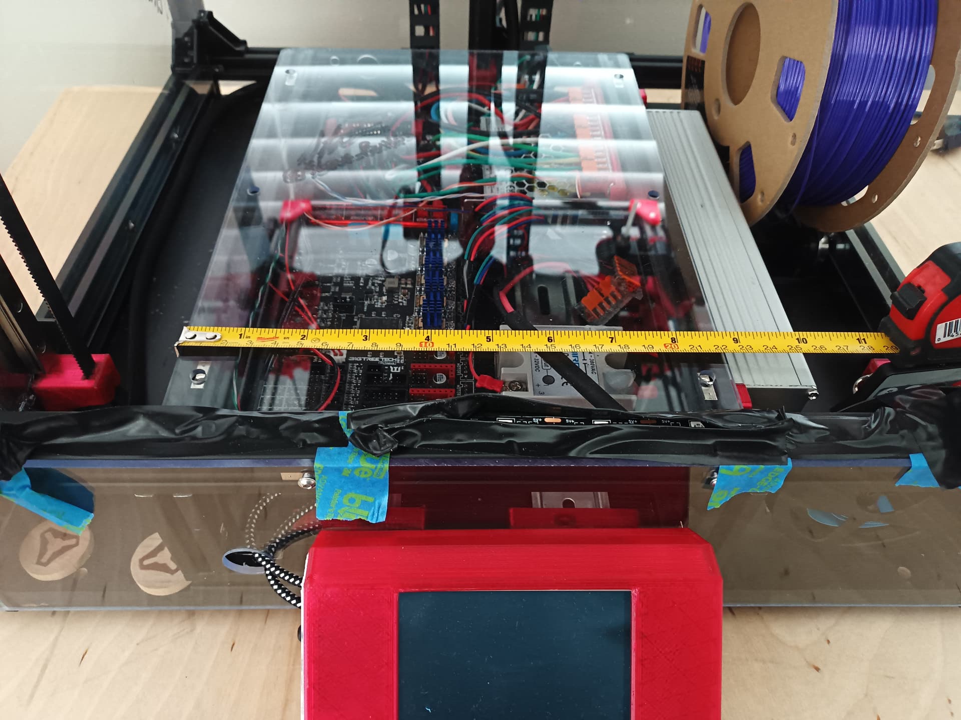
Currently, managed to fit Octopus, SSR, 5V PSU plus misc connector blocks inside 220mm (w) x 335mm (d) x 80mm (h). 24v PSU is bolted to right side of extrusion based electronics case. Overall width including 24v PSU ended up being 260mm. PI+3.5" TFT stick out front. Electronic box probably needs additional cooling, and insulation from print chamber.
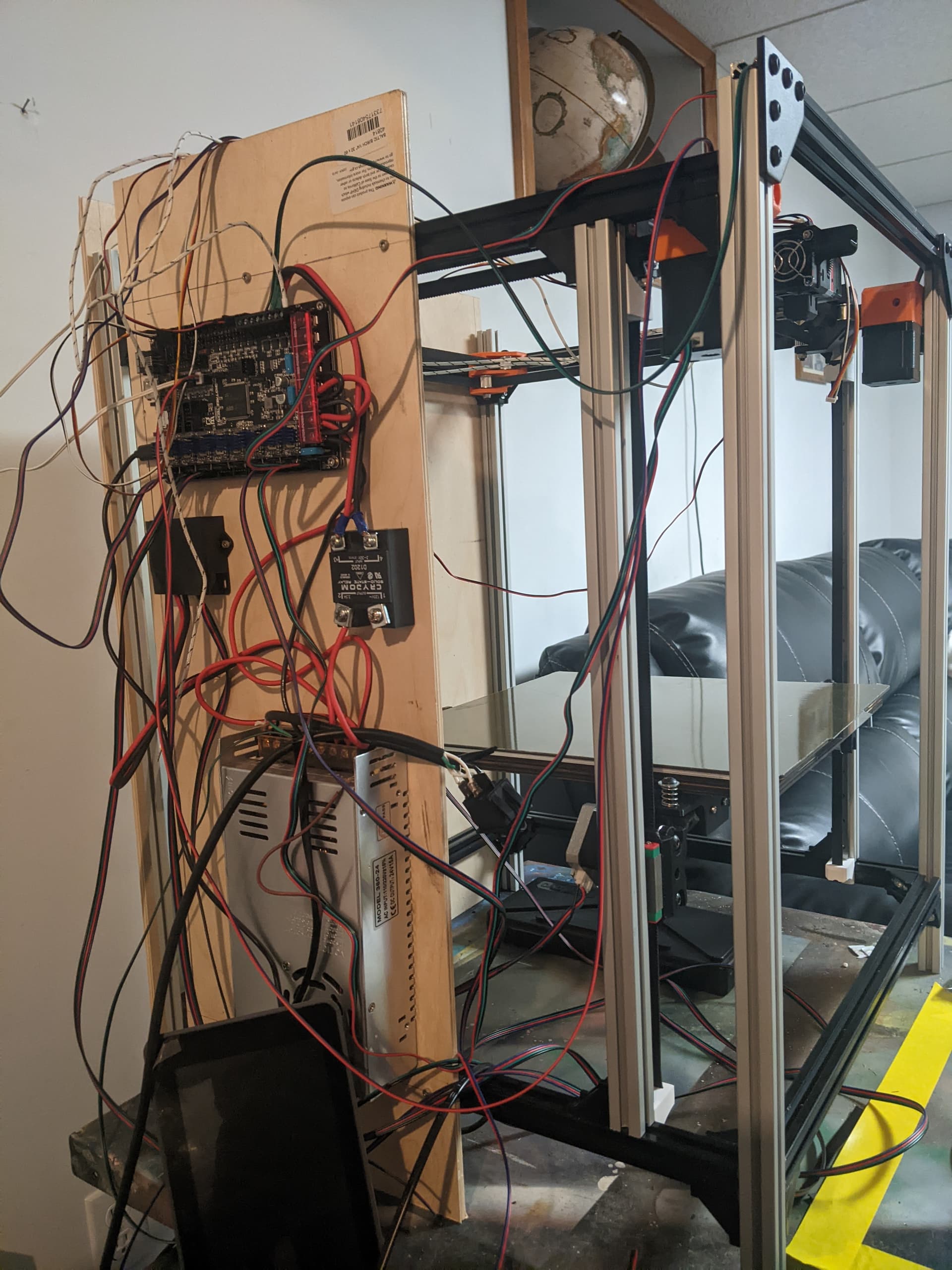
I made a temporary electrical side mount to test motor function before cleaning up the wires. Need to solder a power switch and flash the controller, but it is getting real.
The other reason for the side is I will need to make a wire extension set for all the wires from the extruder trolley because they are not long enough to reach the bottom. as it sits, no extra wires need to be made for initial testing…
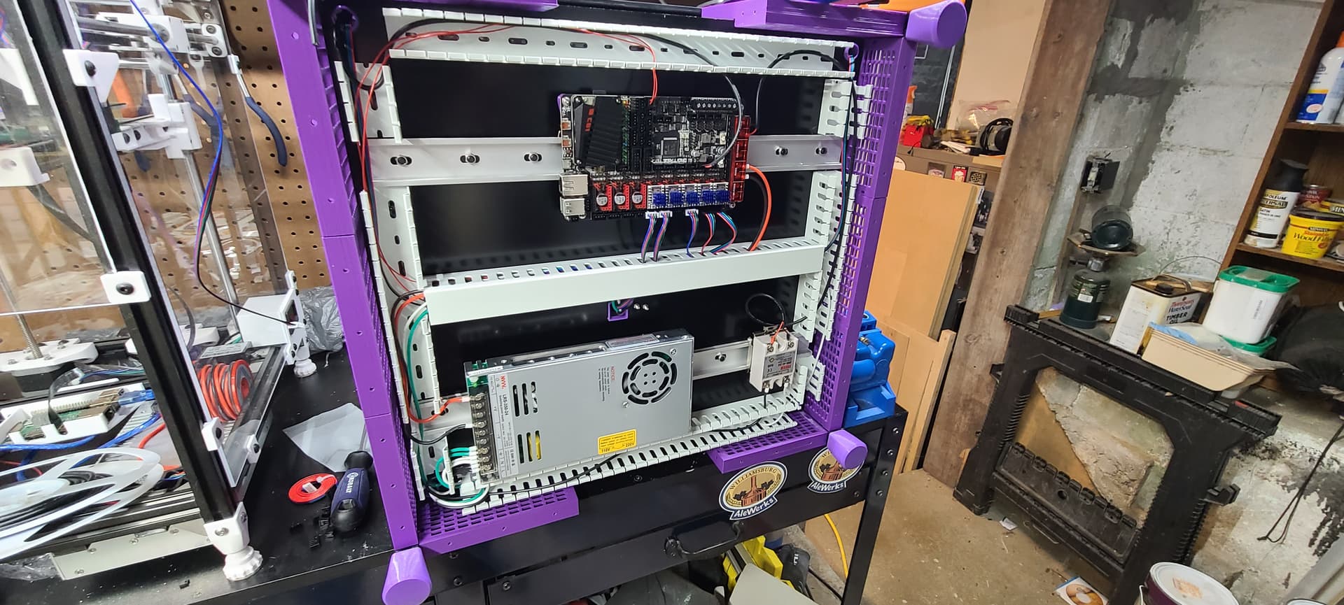
All my electronics are bolted to a bottom plate and hung from underneath the machine. I used ACM panel for it and cut it on the MPCNC but it could just as easily been done by hand.
So I need a part cooling fan mount for the H2V2S… Any thoughts?
Oh, and in case anyone cares: no, I’m not embarrassed of the wiring spaghetti photo from before. My son is embarrassed for me because he is super anal about tidy wiring. I told him when I’m done he should be marginally ok with it, but not likely proud. Who else decases all their electronics so they can exactly space components to look perfect… not this guy.
My experience is that the same folks that put effort into making wiring clean also end up with wiring that doesn’t snag, work free, pinch, bind, or short…
In other words, rats nests are often broken. Clean setups generally are not.
Served me wrong… Just ordered another octopus. The smoke was released with a little flash of light and a pop. I just wanted a mockup to see if motor movement and thermal sensors were functional before cleaning it up and first power killed it.
I will add that just because the wires were not pretty doesn’t mean they were not in the correct place. This isn’t my first rodeo. Likely user error for sure, but no idea what happened. The silver box on the half of the board opposite the USB smoked. But one of the 2209s arced nearest the USB and lit up for a split second before the pop and smoke.
I agree with your comments that clean builds tend to last longer and not fail with normal use and are simpler to service in the long run. The effort to clean up was to come after the functional test so I didn’t have to rerun wires in the loom and rethread and attach again. I had no plans to actually run it in that shape other than verify the wiring, directions, channels, etc. The comment was about the fact that even my efforts to clean up to ensure reliability would still not be sufficient for my boy who is super meticulous about it…