Generally 3 points is better so you don’t make the plane into a saddle. 4 can help with some things but I have never used 4.
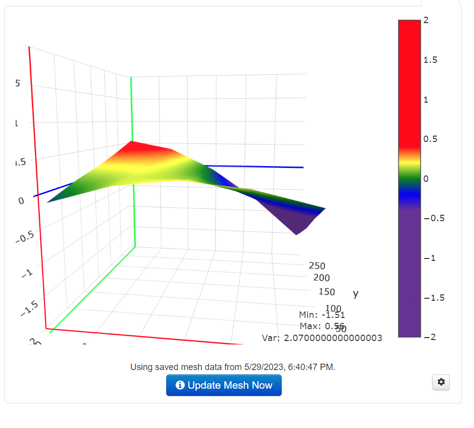
At this point I would take a much closer look for anything loose or pushing on the center core. That is the only way you can possibly show a 3mm deviation that does not show up on a straight edge.
If the Alu bed surface is true level, stiffly fastened with springs tight, and held up by three points, suspending the Alu surface in a single plane… then is it possible that the surrounding rails/frame held at 4 points, and/or flexing X rail, are contributing to the saddle shape being measured? This is a bigger build (300x300x400mm), could heavy/stiff umbilical wiring be contributing to up/down forces, and/or twisting forces about the X linear rail in certain X-Y positions?
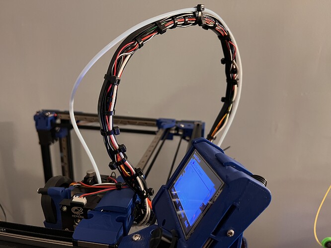
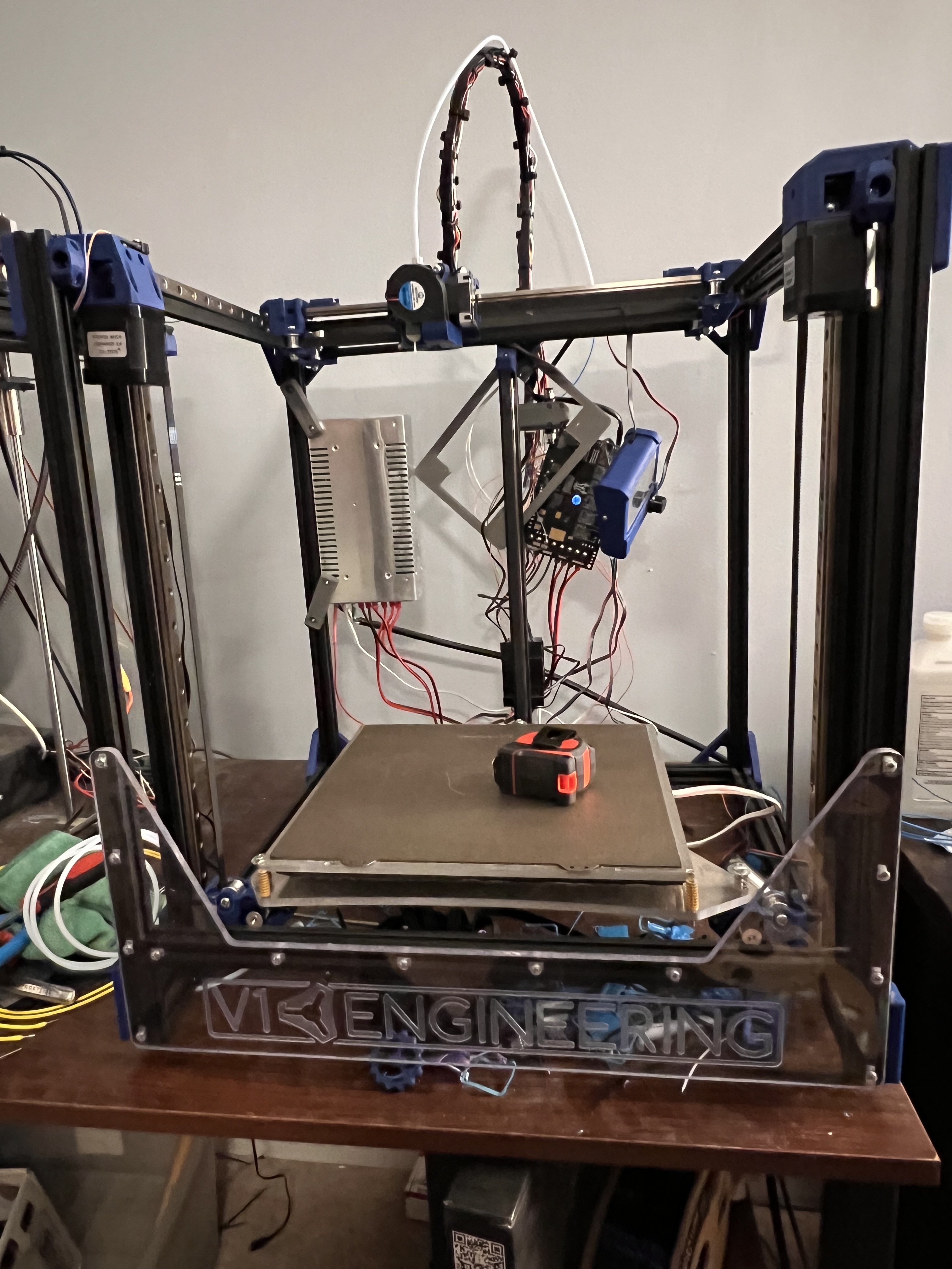
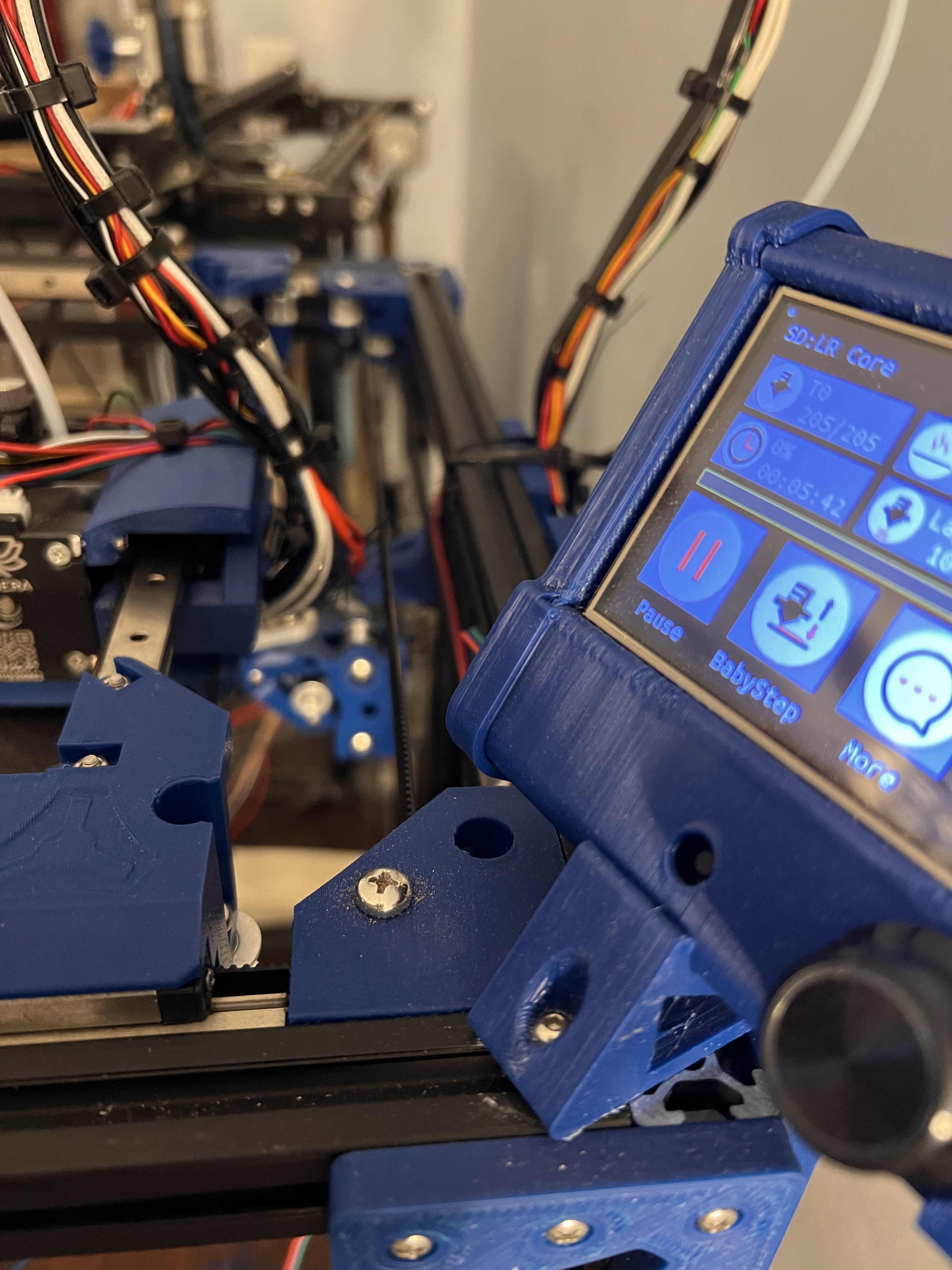
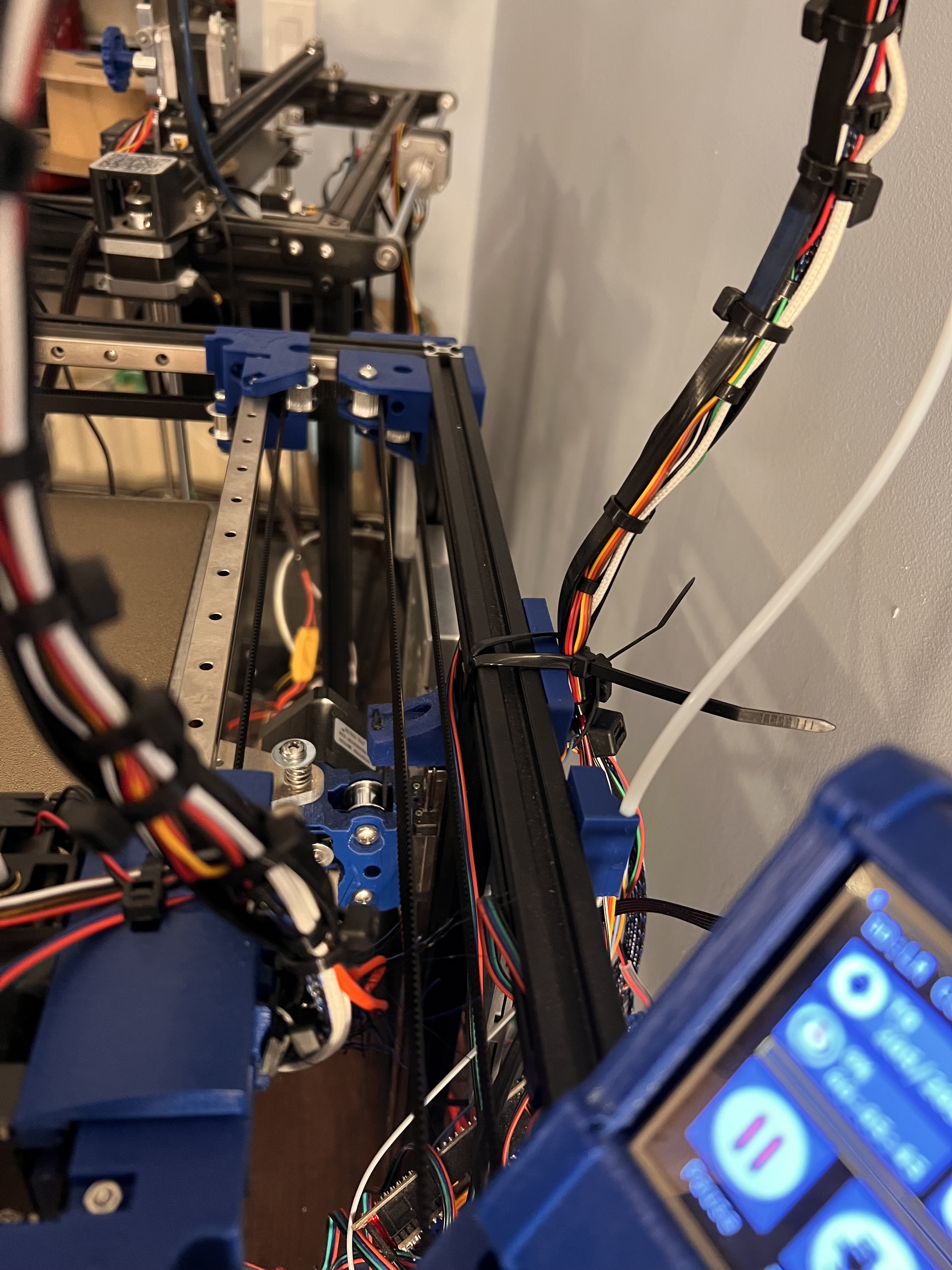
Curious how the gantry setup is looking currently, here’s most recent pic I could find…
That pic is accurate to how it is right now. I have found no other way to ease that up anymore. it seems to flex just fine as the head moves around and I see no binding in it at all.
I will check this as soon as I get a chance and report back. This is part of the reason I was thinking about doing the acrylic cuts already. Hoping it would hold the frame better incase that’s part of my problem.
I can sure try. Do you have an STL you suggest for this? Or should i just make a square in fusion?
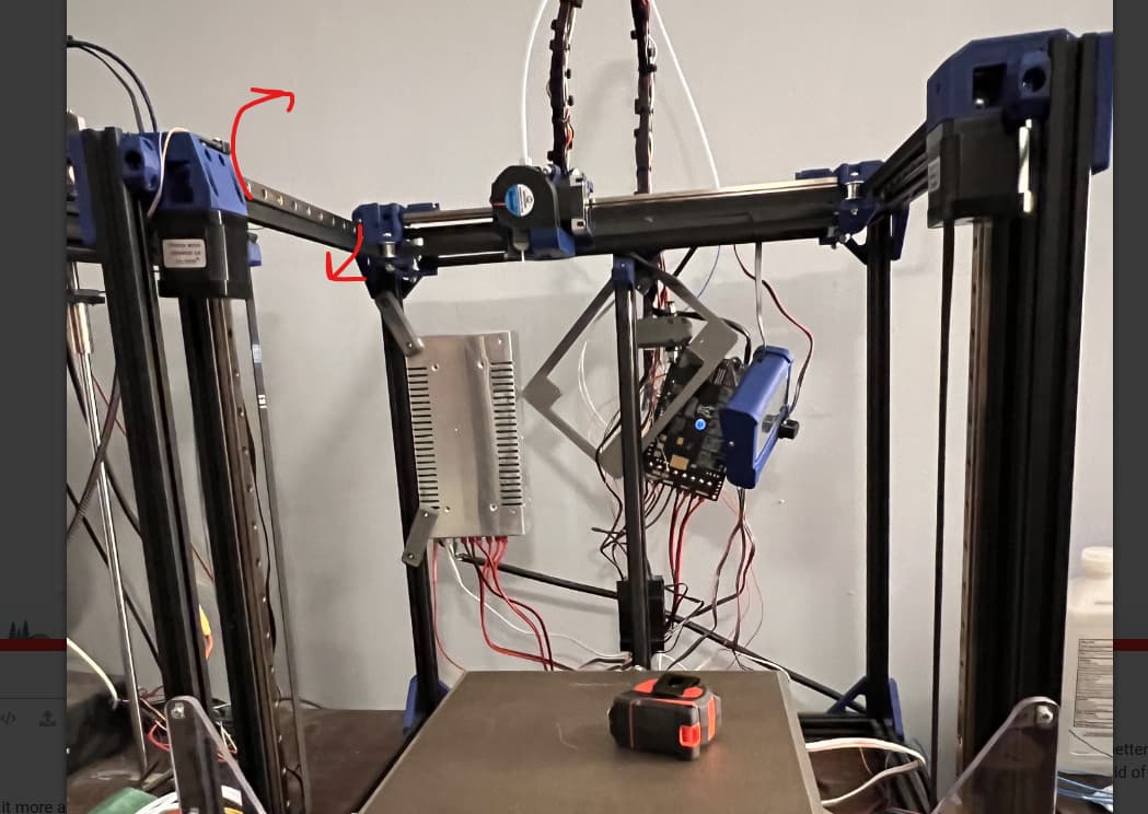
We are all worried about this one, but if you think it has no effect that is good. The fact that is stands on it’s own it was seems to trigger us I think. You seem to have lots of free space. An easy test if your wires have room is to move the connection point at the back over as far as possible and see if it changes your visualization.
This video I just watched today shows how 4 points can make a saddle and how a twist can’t easily be detected with a straight edge (the one they made from the bamboo rollers was made from straight lines).
Ok top on the list today is locate some M2.5 nuts. I could have sworn I had some but I cant find them anywhere. After that I will try the test print again and see if it comes out square and report back. right now the bed just wobbles too much. Going to have to tighten them down some to take that out of it.
That is really really far out and you can probably see the cube flex as it moves front to back.
Usually that is the front panel. The X rail comes into play here and the back panel sets the actual width so start there and set the X rail in the trucks. Then you need to fix the front panel to be the same width as the back. Keep an eye on things and recheck all the rest of the diagonals.
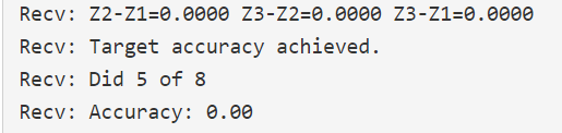
Adding a probe that dials things in to 0.02mm means everything needs to be pretty accurate. All my diagonals are under 1mm. Since things are over constrained, the rails need to be near perfect or they will move/bend.
No worries from any of us, I am sure. We like to solve problems, doesn’t matter when.
Currently I have no panels just the extrusion. I was hoping that by using the DXF from your cad that making the panels will force everything correct. So which panel do I need to worry about first?
I’m on strike 3 with this stupid tubing for the air blower so I may just stand there with an air hose and try to cut some panels today. I’m over it and starting to run out of time with everything going on at work.
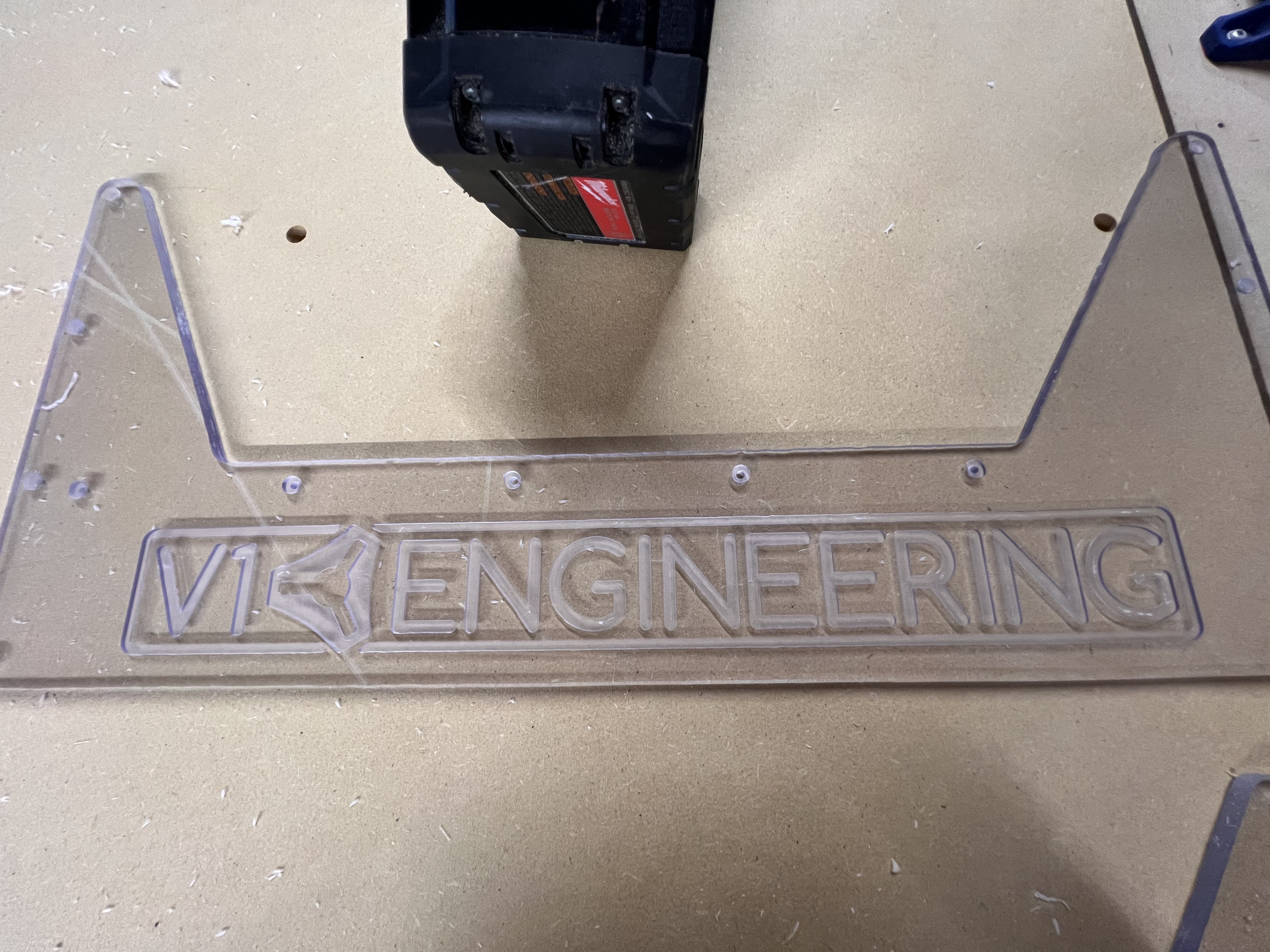
Hopefully @vicious1 is happy with how the logo turned out. Always try to do it the most justice possible
And just wow… this is it sitting on top of the bar across the bottom. Obviously it’s not square at all. And I spent an hour squaring in the LR3 before this cut so there’s no reason the new panel shouldn’t be square
First panel installed. HOLY that was a job. But its insane how much just that one panel stiffened up the entire frame!!! Next I think I’m going to cut and install the back panel. Then ill worry about the sides and the bottom.
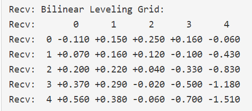
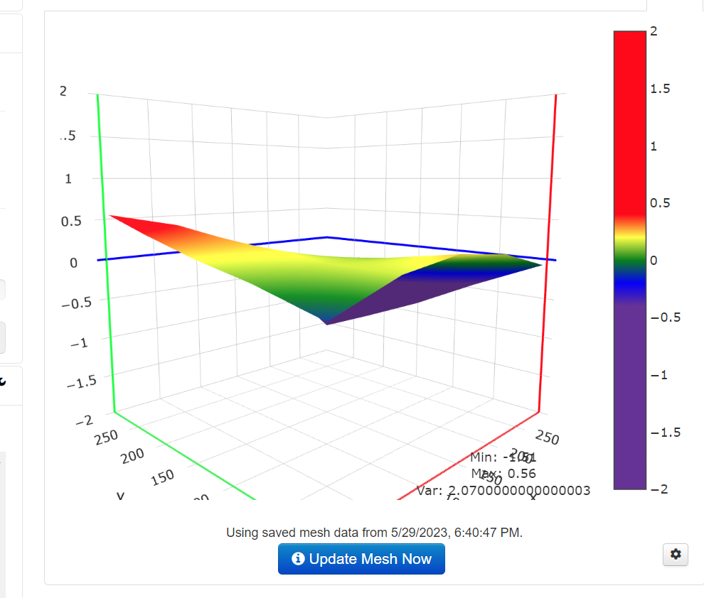
A 1.5mm dip seems kinda big. I think it could work if you turn the leveling fade up to 10mm or so, maybe even a more just to be sure.
Fake it and lift that corner up with something to see what happens. like put 5 layers of Blue tape in that low corner and make sure it covers a few probing spots. See if it changes or not. Along that side you are showing a total of 2mm out.
You are sure the trucks are not hitting the rear corner blocks when it is probing?
Hopefully each panel force it more and more square and that dip gets better and better. After the XY squaring, the YZ squaring might reveal some more easy tweaks to get rid of that dip…Actually That is something to try.
Loosen the screws and try rotating the rail into the dip. Away from any high spots and into the low spots. That might actually be a great way to level the rails before doing a YZ test print that takes about an hour and a half each. I need to try that on my printers…except I just tuned every one of in the last two weeks.
I am hopeful as well. LR3 is locked down with another important project that I NEED to finish…and would be finished if I didn’t keep making mistakes LOL. Cost of learning!!! Once this sign is out of the way I hope to cut the rear panel. The only thing I set up for additional holes on that was for the power supply. I believe I’m going to put the SKR on the right side if looking at it from the front. I have more room on that side. I thought I had ordered 2 24x48 panels but turns out I only ordered 2 24x24. Got 2 more on order now. I leave first thing in the morning for GWO training for work and wont be back until Friday night. Hoping it will be here by then and I’ll get to cut the side panels this weekend. I got greedy last night and set the LR3 core to print. It was looking ok… Infill wasn’t laying like it should. I think I had it set too fast. And I tried to do .4mm layer height instead of my normal .3mm on a .6mm nozzle. It was less than an hour from finishing when octoprint lost connection and the bed dropped. That’s why I usually just print from SD card… Oh well. It wasn’t right anyways. Bothering me that ive printed half of the new LR3 parts on my creality when i have a V1 printer right here LOL.