Those are really nice looking. I could use those in the future.
Installed the Bed and was looking at space. I think with some low profile rollers I can put the spool inside!
2 Likes
Will you be able to change a spool mid print, or change the filament change to go to Z max when changing?
1 Like
Thinking about putting a hinged door on the right side to reach into it. Sadly I feel the ERCF in my future also so that will take some thinking later.
I don’t normally do prints that use more than a spool and when I am a dumb ass and overprint a spool I make scrap ![]()
2 Likes
Anyone that is using the Manta M8P and CB1, what screen are you planning to use. I have been reading a lot and the TFT35 SPI says it is supposed to work but a lot of comments say it does not. Thought about the BTT HDMI5 but not sure i care to have that much screen?
Thoughts?

Good luck. I wish I had left a little more room for cable runs. My plan is to try to cable lace everything instead.
As a retired Navy guy, I totally appreciate cable lacing!
1 Like
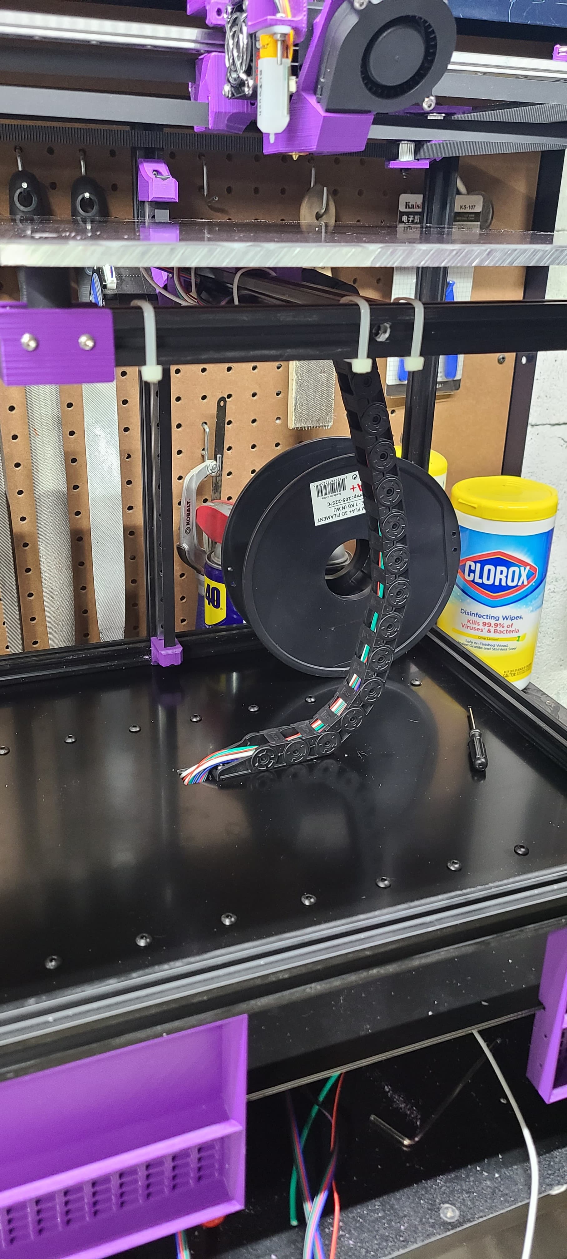
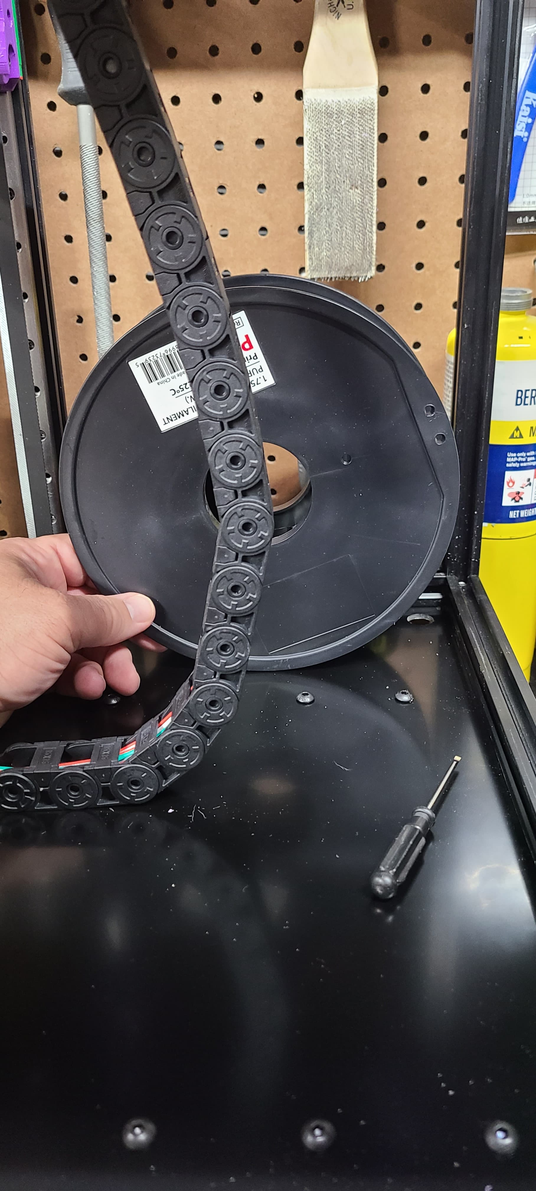
Making some progress. Using a section of flexible Cat6 cable to make the CAN cable from the hotend. Super wierd having only 4 wires to handle all of the hotend requirements!
3 Likes
I might have to look into the canbus thing for a future upgrade.
1 Like
Neat idea. Stranded wire? Pumping 40W+ through and splitting (parallel) the current across multiple wire pairs?
Yes. 2 sets of pairs for the power and one set for data. I expect I could separate the last pair across the power side but was worried about space in the pins and connecter. Stranded wire for flexibility.
3 Likes
So… the Micro Molex connector on the EBB36 is a serious pain in in the rear.
Two things for those that are looking at using them.
- Make sure you know EXACTLY what the pinout is. Once you put the pin in the connector it takes a special pin removal tool to get them out.
- Strip back enough so that the connector does not have any torqu on it. The wires will pull right out of the pins and see point 1.
New connectors are on Amazon. They will be here today.
3 Likes

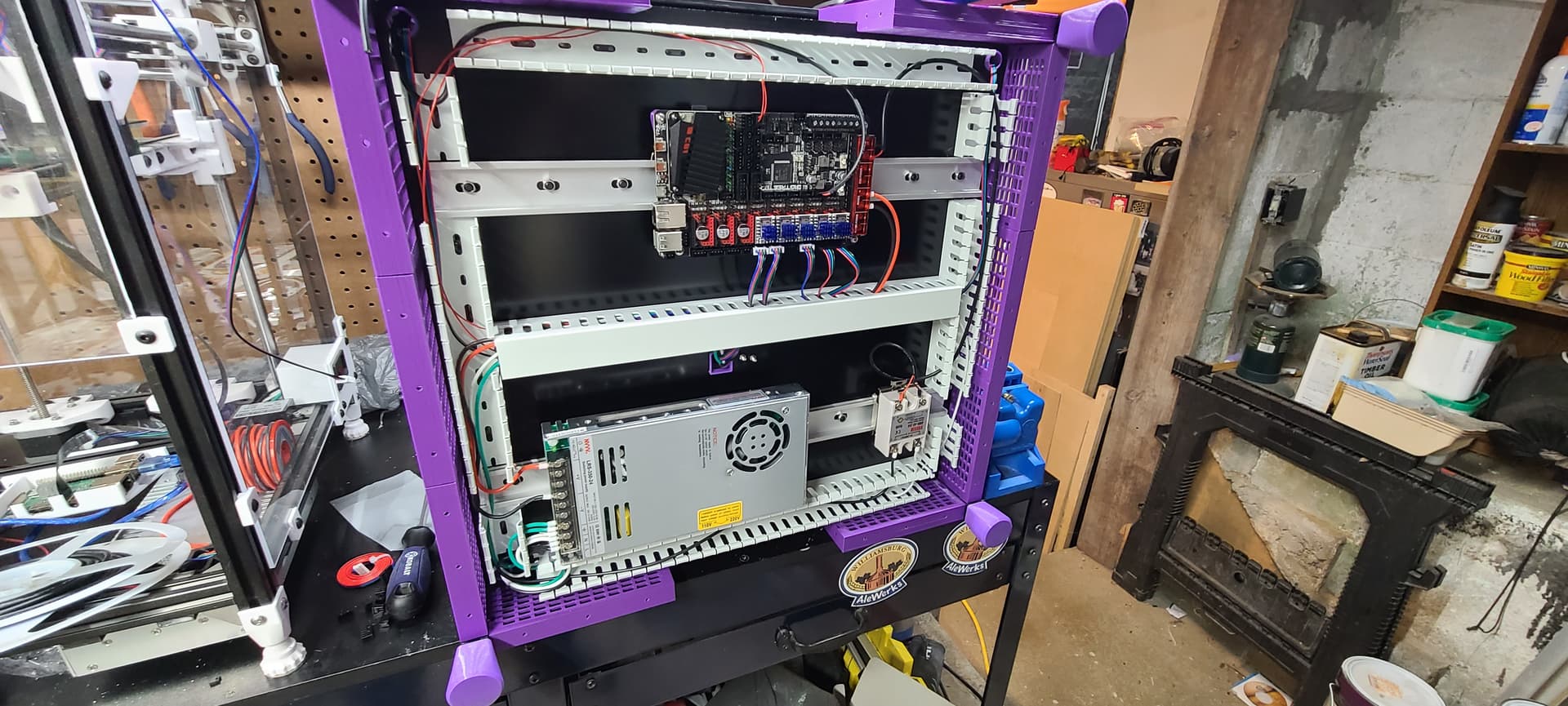
Getting the wiring buttoned up. Learned a few more things about the Manta M8P:
- You have to jumper in power to the Bed Power terminals for it to output anything on the the Bed out terminals
- Dont forget the jumpers to select where the drivers get power from.
Still trying to figure out the CAN BUS thing. I have it all wired up but the EBB36 does not show up as a CAN MCU. It has been flashed with CanBoot but I need to be able to see it to put Klipper on it. I THINK it has to do with the 120ohm termination. There are what look like jumper pin and I am not sure (and can not find any reference) as to whether I just need a jumper there or if I need to wire 120ohm resistors into those terminals.
3 Likes
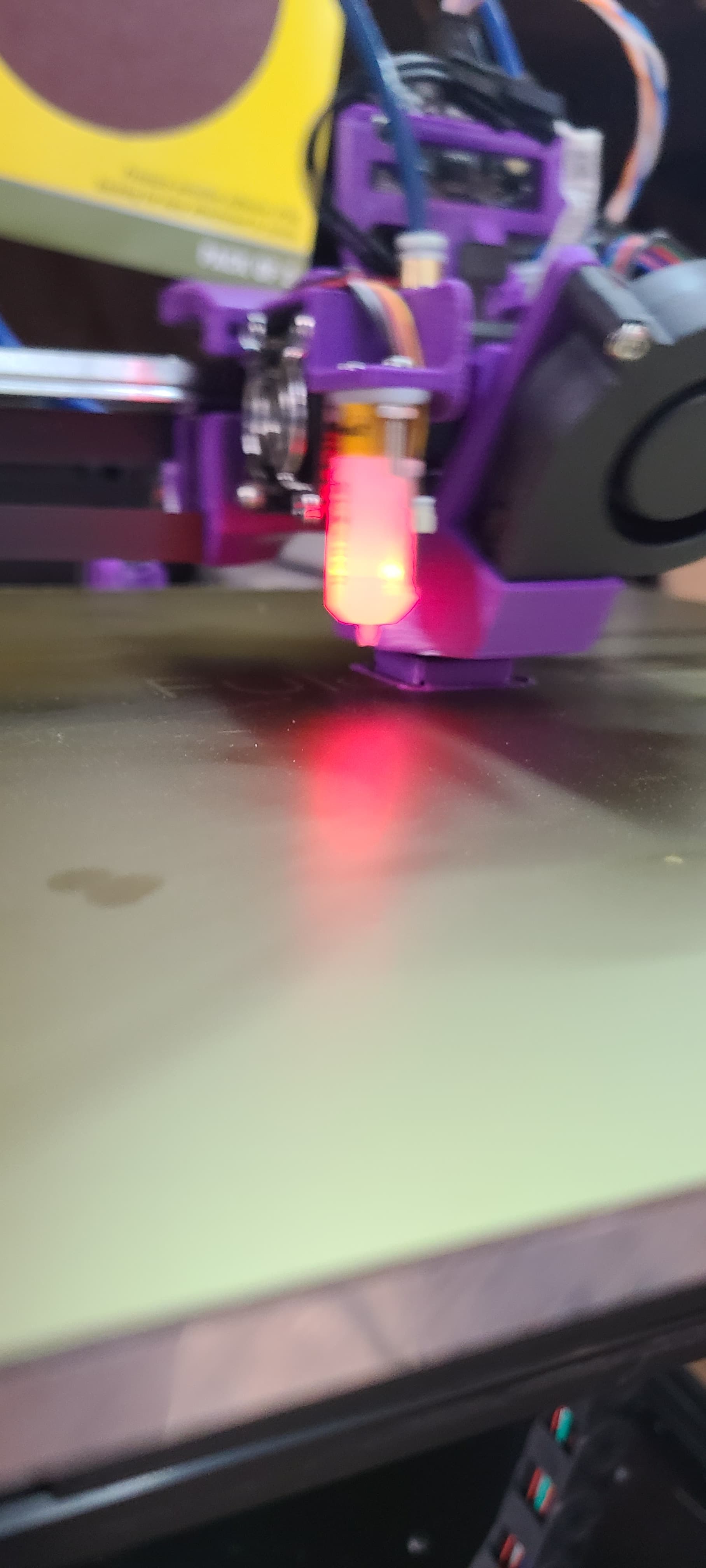
It is alive! I can get it to home all axes. But when I do the tilt_adjust it fails.
I would love any insight on this. It probes all the points. I started out probing front left, back middle, front right. Though maybe it needed to be in the order of the motors so I changed it to front left, front right, back middle.
It got worse. HELP!
Retries aborting: Probed points range is increasing.
8:04 PM
Retries: 4/10 Probed points range: 0.420000 tolerance: 0.005000
8:04 PM
Making the following Z adjustments:
stepper_z = 0.000291
stepper_z1 = -0.227804
stepper_z2 = 0.232627
8:04 PM
probe at 150.000,250.000 is z=0.845645
8:04 PM
probe at 150.000,250.000 is z=0.845645
8:04 PM
probe at 285.000,50.000 is z=1.265645
8:04 PM
probe at 285.000,50.000 is z=1.265645
8:04 PM
probe at 50.000,50.000 is z=1.055645
8:04 PM
probe at 50.000,50.000 is z=1.055645
8:04 PM
Retries: 3/10 Probed points range: 0.235000 tolerance: 0.005000
8:04 PM
Making the following Z adjustments:
stepper_z = -0.027465
stepper_z1 = -0.115645
stepper_z2 = 0.138491
8:04 PM
probe at 150.000,250.000 is z=0.911029
8:04 PM
probe at 150.000,250.000 is z=0.921029
8:04 PM
probe at 285.000,50.000 is z=1.151029
8:04 PM
probe at 285.000,50.000 is z=1.151029
8:04 PM
probe at 50.000,50.000 is z=1.001029
8:04 PM
probe at 50.000,50.000 is z=1.001029
8:04 PM
Retries: 2/10 Probed points range: 0.145000 tolerance: 0.005000
8:04 PM
Making the following Z adjustments:
stepper_z = -0.027811
stepper_z1 = -0.061029
stepper_z2 = 0.093899
8:04 PM
probe at 150.000,250.000 is z=0.953439
8:04 PM
probe at 150.000,250.000 is z=0.953439
8:03 PM
probe at 285.000,50.000 is z=1.093439
8:03 PM
probe at 285.000,50.000 is z=1.103439
8:03 PM
probe at 50.000,50.000 is z=0.993439
8:03 PM
probe at 50.000,50.000 is z=0.983439
8:03 PM
Retries: 1/10 Probed points range: 0.270000 tolerance: 0.005000
8:03 PM
Making the following Z adjustments:
stepper_z = -0.153439
stepper_z1 = 0.047783
stepper_z2 = 0.145280
8:03 PM
probe at 150.000,250.000 is z=1.009637
8:03 PM
probe at 150.000,250.000 is z=0.999637
8:03 PM
probe at 285.000,50.000 is z=1.109637
8:03 PM
probe at 285.000,50.000 is z=1.119637
8:03 PM
probe at 50.000,50.000 is z=0.849637
8:03 PM
probe at 50.000,50.000 is z=0.839637
8:03 PM
Retries: 0/10 Probed points range: 0.840000 tolerance: 0.005000
8:03 PM
Making the following Z adjustments:
stepper_z = -0.599637
stepper_z1 = 0.258988
stepper_z2 = 0.329730
8:03 PM
probe at 150.000,250.000 is z=1.060000
8:03 PM
probe at 150.000,250.000 is z=1.060000
8:03 PM
probe at 285.000,50.000 is z=1.200000
8:03 PM
probe at 285.000,50.000 is z=1.200000
8:03 PM
probe at 50.000,50.000 is z=0.360000
8:03 PM
probe at 50.000,50.000 is z=0.360000
8:02 PM
BED_LEVEL`
1 Like
Left is Z1, right is Z2, rear is Z3.
G28 probes the middle, G34 does them in order then backwards, etc until it is level.
All those numbers you are showing make no sense to me, how did you get them? G28, then G34 should give you a different data set.
It also looks like you moved your BLtouch, did you input the new coordinates/location?
I thought maybe I had it as I had the motor order wrong and the pins were incorrect. But they look right.
I am running Klipper on the machine so that may explain the different data format. g34 is an unknown command in Klipper. It uses Z_TILT_ADJUST instead.
I have the new offsets for the BL Touch in my config file.
1 Like
Alright. I dont know why but for some reason my motors are backwards. They are plugged in correctly. But I changed the pin assignments and like magic it worked! .005 tolerance on try 4!
4 Likes
I have my machine up and running Klipper on the Manta M8P using CAN BUS for both the MCU and the EBB36. I was having a chat with @gpagnozzi and told him I would post how I did it for future knowlege.
I used the procedure here: https://github.com/Arksine/CanBoot/issues/61 to get the Manta up and running. A quick note. When you get the CAN ID write it down as you may not be able to see it in the future.
For the EBB36 I used this process: https://maz0r.github.io/klipper_canbus/toolhead/ebb36-42_v1.1.html
Still to do:
- Finish skirts and add fans
- Design bezel for TFT35 SPI screen
- Cut and install ACM Panels on sides and back
- Mount WiFi antenna
- Mount spool holder on back right wall
- fabricate Plexi door for front
- Install lights and camera
- Wrap the bowden and Canbus cable with wire wrap vs the cable ties.
And of course more tuning. I printed a semi successful calibration cube after doing pressure advance and input shaping. It looks great except for the front left corner above and below the X on the front. I many have a retraction configuration issue although it does not make sense that it doesn’t do it the entire way up the cube. I have a feeling it is more from Temperature and that corner is the seam placement so it slows down more when the next move after the corner is slower.
1 Like