Minor Error in the LR3 Build Documentation?

I’m partway through my LR3 build, and I came across something that confuses me. I’m guessing that it is an error in the documentation, but it just as possibly is an error in my understanding.

The picture of the Core is accompanied by a caption that says “Now is a good time to add your touch plate wires if you are using one”, and shows the touch plate wire harness laid in place beside the stepper wires:

However it shows the Molex connector just under the motor. Shouldn’t it show the end with no termination, where the touch plate and alligator clip attach? (Molex conneector attaches at the controller end, no?).

Also a small bit of text as to how much excess wire to leave near the motor (so the touch plate and alligator clamp can reach the bottom of the router) might be helpful for us complete noobs, before all of the tie-wraps get cinched tight. The picture doesn’t look like the wiring is long enough to reach where it needs to go.

If you look closely at the photo, in the photo the touch plate wire for documentation purposes has a connector at both ends. Their are no none connector wires in the photo.

There are two connectors visible at the top of the photo. One is for the stepper motor, and I was guessing that the other is for the end switch.

The touch plate wiring I received as part of the kit only has a connector at one end.

The kit also came with an alligator clip (screw terminal), and a crimp connector that attaches to the plate, both of which need to be attached to bare wire. Unless the design has recently changed and a Molex connector used to attach to a pigtail that attached to the plate and alligator clip??

Don’t have a precise length for you. But hope this helps…

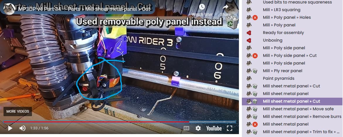
Rightly or wrongly, I tuck the touch plate up behind the router. Note I ended up adding/replacing the Dupont connector on the Touch Plate wiring, used some HeatShrink to reinforce the connection after I broke the initial connection/wire.

I feel the part that is being lost in translation, because of my poor choice of phrasing is:
The documentation could be better, if Ryan became a dictator, and said from this point forward, every machine build will be X by Y size, using this size tubing, and made the kits accordingly.

However, Ryan has gratuitously given us options, and what I think of as “starter” kits. He has calculators to help us decide how big we want our build to be, informing us of the length of tubing we will need to source, etc.

Because he has given us the ability to choose the size, and other options, thus in turn means certain information in the instructions has the be “generalized”. If I chose to pick on the documentation, it would be that the instructions should state that everyone needs to read and understand the instructions before they start printing OR ordering parts. (And yet it’s probably there and I’ve forgotten).

So, to your first question you are correct, you probably want the connector away from the core. That’s the way I did it, and it worked for me. I’m still of the opinion that Ryan had the cable there just to show placement OR I’m forgetting that the cables used to be double ended, and most customers were cutting one end off, so Ryan made a change to save cost. Honestly don’t remember.

To your second point, the instructions would need to know, where you plan on positioning the controller, the width of your gantry, and the routing of your wiring. Aka: zip tied to vac hose, cable chain, some other route. Then if we knew the length of the wire you received, then someone could estimate the length you have as spare, to leave at the core. With that said, I would suggest 2 inches max for now. But setting expectations I would also recommend that you not tighten zip ties tight yet, you will be making wiring adjustments as it comes together. You want things to keep the wires safe as you continue your build. And certain wires are sandwiched between parts, but you more than likely will be “adjusting” wiring as one of the last steps, if nothing else securing it, and you won’t know where YOU will want to run the wires and secure them until near the end.

Ryan has a good video showing workflow, and his wiring for his touch probe for some ideas. @azab2c has provided the video with his. Others have placed a plugin jack, to be able to plug their probe in, and remove it when they are done probing.

Does that help?

1 Like

I think the molex connector in the picture is only for reference, You can connect the touchplate directly on cables, or You can connect it to another molex that goes to the touch plate, this gives you the possibility to modify the touchplate’s cables length after finishing your build with ease.

I had the same question during my build and didn’t really find the answer. I just left a little bit of slack in the zip tie until the very end.

I then found out the wire wasn’t long enough for me to reach across and I had to extend it.

I may have more excess than others, but I believe my wires extend roughly 6-8" beyond my router. I then use the magnet to stick the alligator clip to the side of the motor, and tuck the touch plate behind the router at the top of the core.

It’s not super tidy, but it gives me plenty of extra to maneuver around. I also have a bit of extra length in my cable chain that I can still adjust if necessary.

1 Like

Sort of, kind of (not really). I understand what you are trying to say, but the question in my mind is not how much wire is needed to route from the core to the controller, or where it is routed, or how. The question is how much wire is needed at the core itself in order to reach to a pretty standard placement of the router bit and collet.

All of the other stuff is variable for sure, and may need additional wire to extend, depending on gantry size, routing, of the cable, and all of the other factors that you mention, but it seems that the length of slack needed at the core would be fairly common between builds using say a recommended model of Dewalt or Makita router.

@Michael_Melancon, @azab2c and others have had the same question during their build (see above), so at least I’m not alone in my wondering.

That would be a simple option if the cable supplied had connectors at both ends. As supplied, I would have to clip the soldered ends, crimp a new connector to that cable, and crimp another mating connector to a pigtail. Doable, for sure, but extra materials would need to be sourced. Not a huge issue, I suppose.

I don’t remember how wide your build is, but if it is near 48" or more, you will likely have to extend that cable anyway.

Mine is 48-49" and as it comes, I don’t think it was long enough to safely reach the core routed behind the router from the Jackpot at the other end.

Yes, if you don’t have another connector, and the crimping tool, the best option is to use the molex side on the board, and the soldered cables to the touchplate side…

1 Like

I bet Ryan just crimps both sides and has a tiny tail for the plate. I can easily see this is confusing from the perspective of someone looking at the parts that came in the box.

IDK what the right solution is. Either we can take a new picture with the tail end the bare wires, or the wiring kits should have a shorter pig tail for the probe, and a longer extension.

1 Like