Thanks for the info Maker Jim and Peter B. Greetings.
3 Likes
Spent the afternoon trying to figure out why the table was so out of square. I began by removing the timing belt holders from the ends of each rail and took cross measurements… it was 94-1/4 x 94-7/8. Last I looked before bolting everything together, it was 94.5 x 94.5. Time to start over.
I had to loosen all the bolts holding the 1-5/8” Y rails as well as the 7/8” cross members. I did find the table itself is out of square but that actually doesn’t matter. Once I got the two Y rails back in square, I tightened one bolt on the printed bracket, then measured again, (repeated this 30 times just to make sure it remained in square) plus carefully bolted the cross members to the table frame. The table held square at 94.5 x 94.5 on the diagonals.
Reassembled everything and ran a test rectangle of 6” x 48”. It measured spot on.
So I decided to cut a part for a customer… and I am happy to report it came out perfectly.
Now I can move on to making the t-track spoil board strips.
BTW, left over 1” foam acts as a great spoil board material.
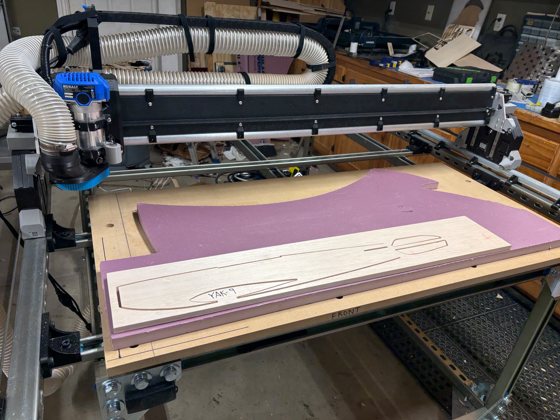
Fuselage for YAK-9
5 Likes
I really like seeing the perfect square dimensions. Kinda feels like magic sometimes.
5 Likes
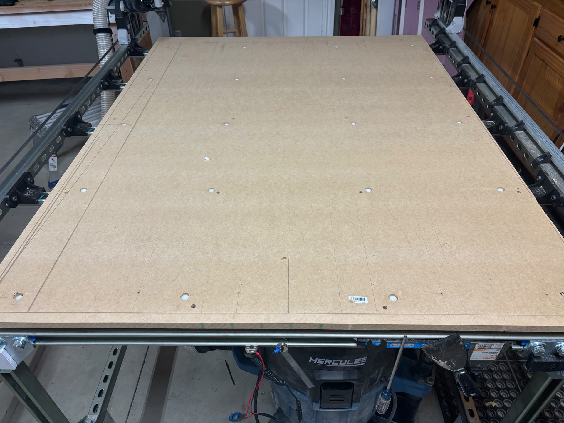
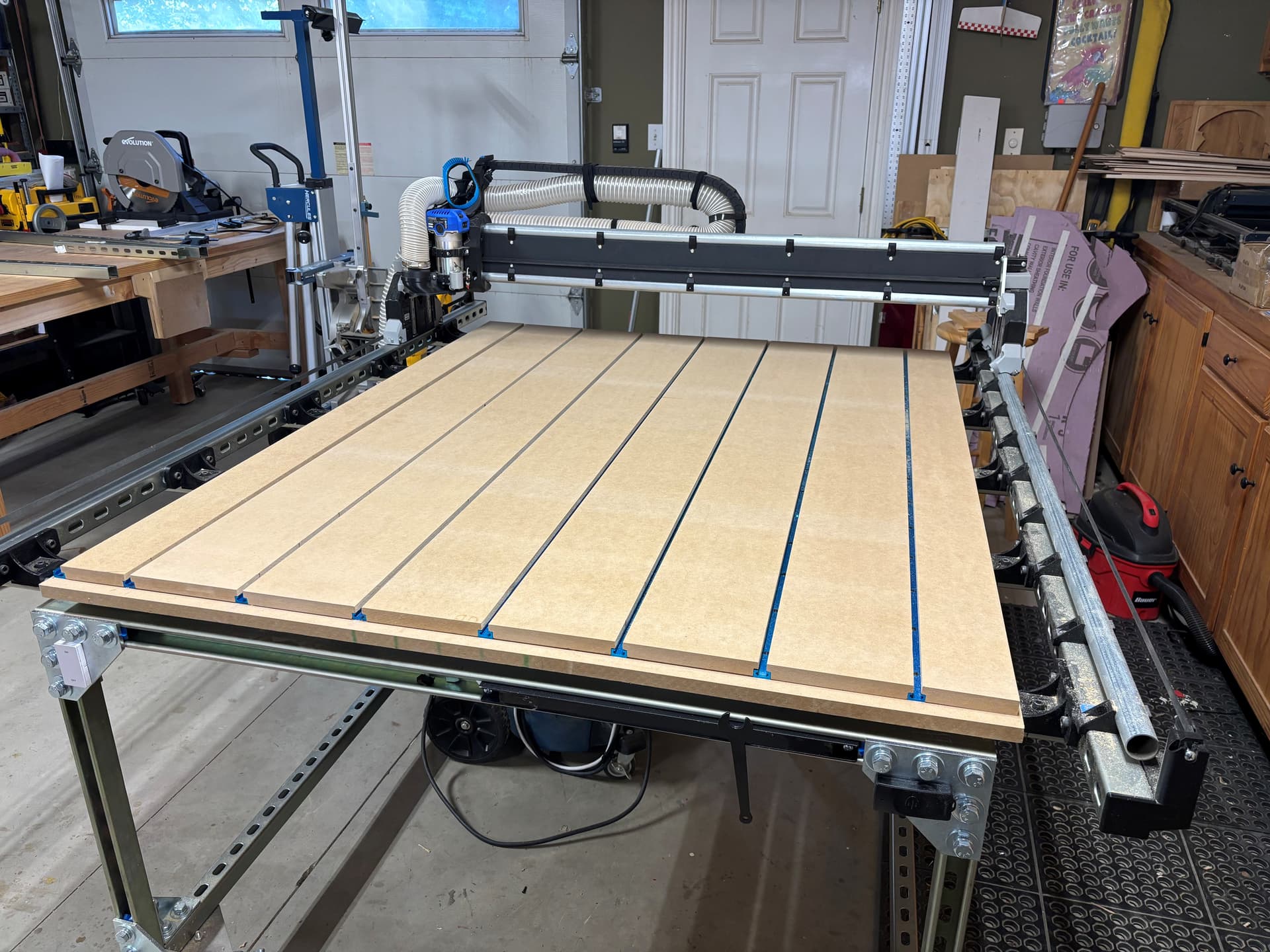
98% up and running…. Now to complete the spoil board setup… got more 3/4 MDF and will cut 60” strips with 3/16 miter on edge to overlap the t-track helping to hold that in place from the clamp pressure when in use. The dust extractor from HF fits under the table so long as I allow it to roll around freely… which is fine. Should be 100% by tomorrow as my wife is going wedding dress shopping with the daughter.. and I have the entire day to myself. LOL
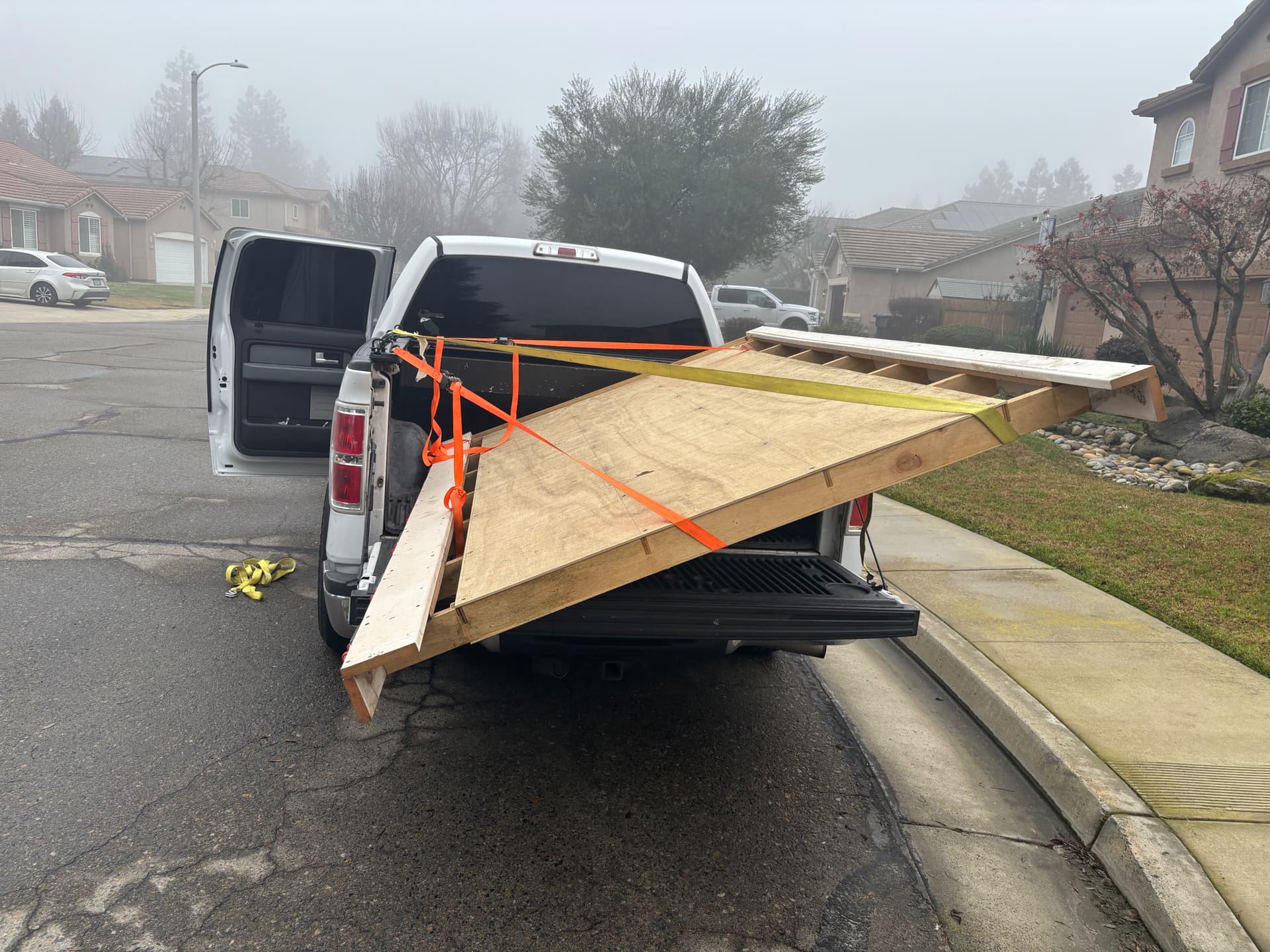
BTW, anyone in the Fresno/Visalia area want the old 4x8 torsion box table top? If so, contact me by 7am PST… otherwise that is the first thing I’m gonna tackle in the morning… its demise and disposal.
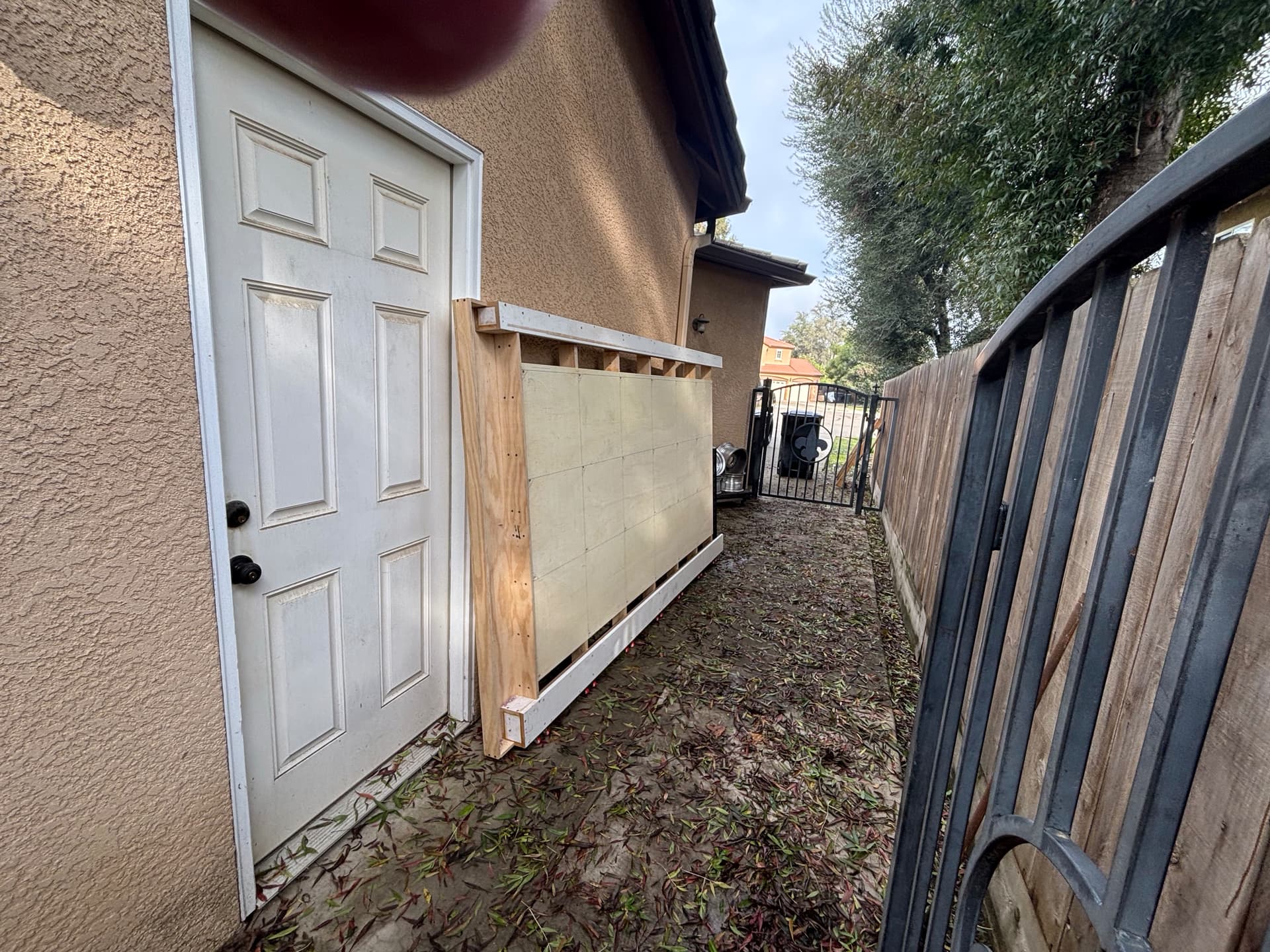
Literally rolls so easy on its side and can be handled by one person but better to have two… I just don’t have room to store it nor do I need it. It would be a shame to throw it away….
1 Like
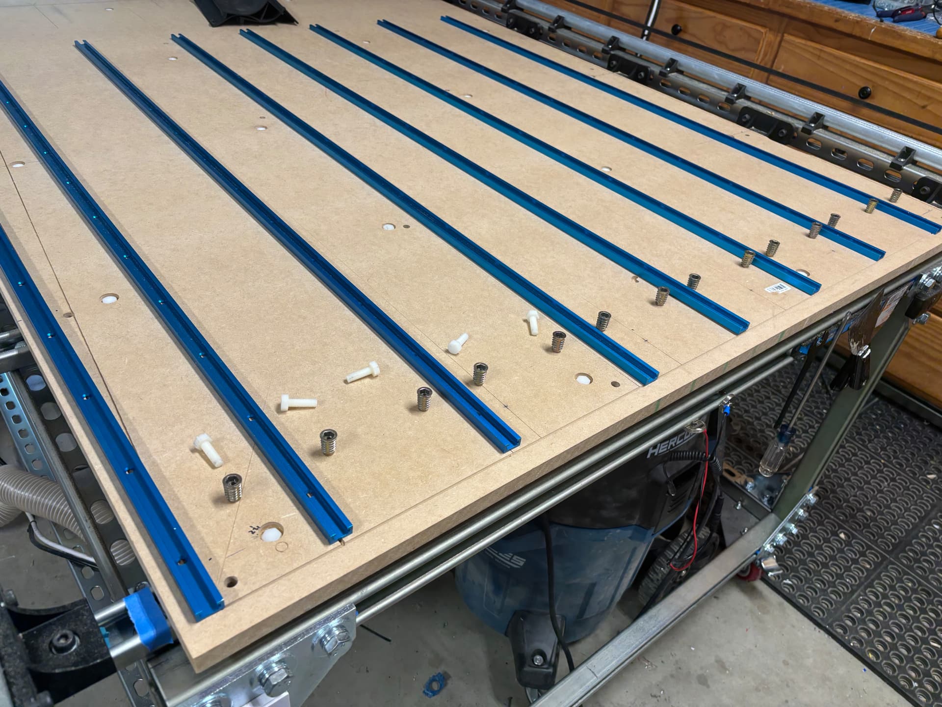
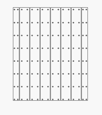
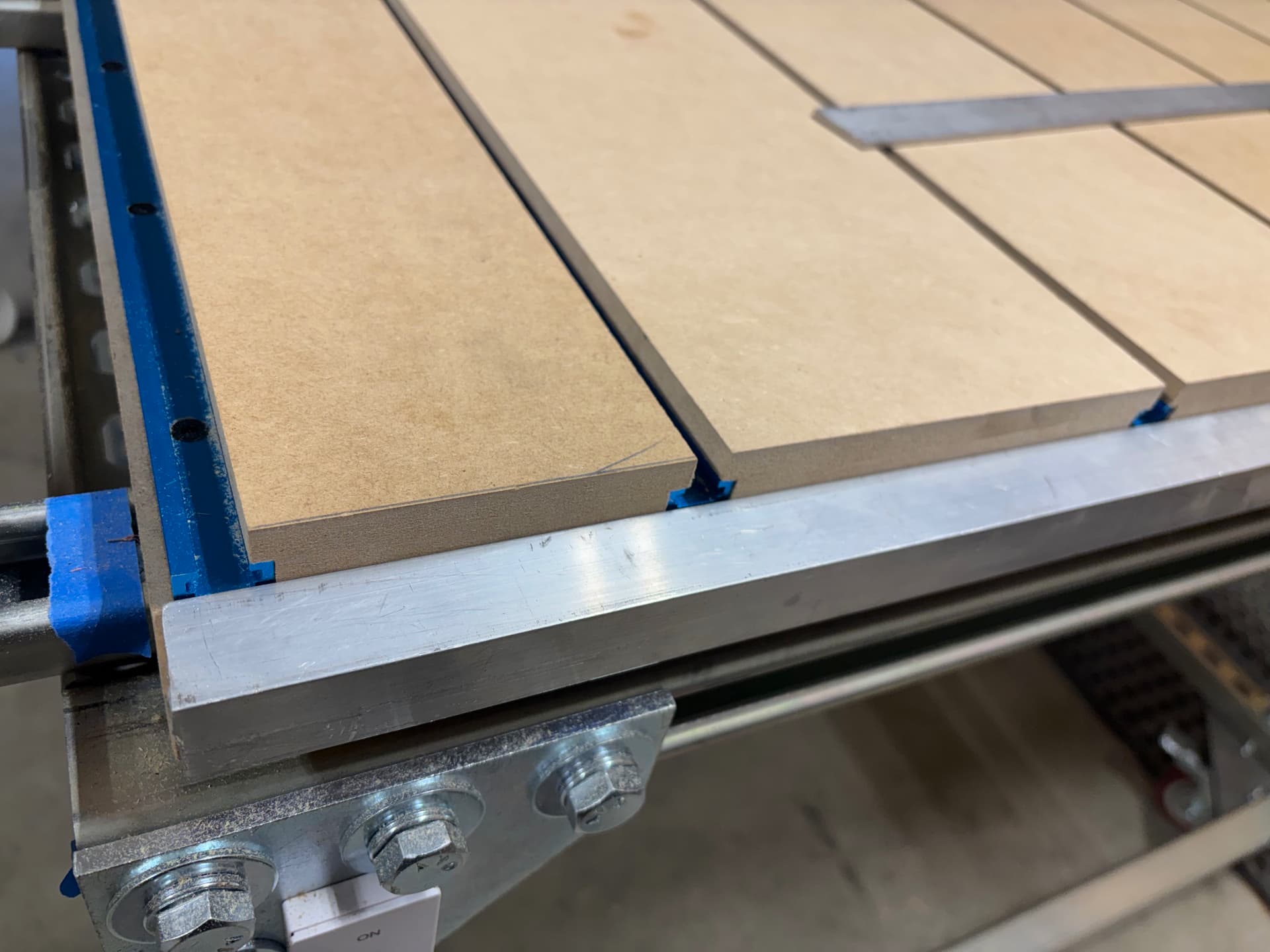
Getting the spoil board strips dialed in
3/16 by 3/8 rabbet will help hold down the T-track plus offer some cushion before hitting it with the bit… but mostly for holding them down

8 Likes
T-track is all screwed down…
Next up, I need to have machine drill and counter-sink holes for bolting down spoil board strips to sub-board.
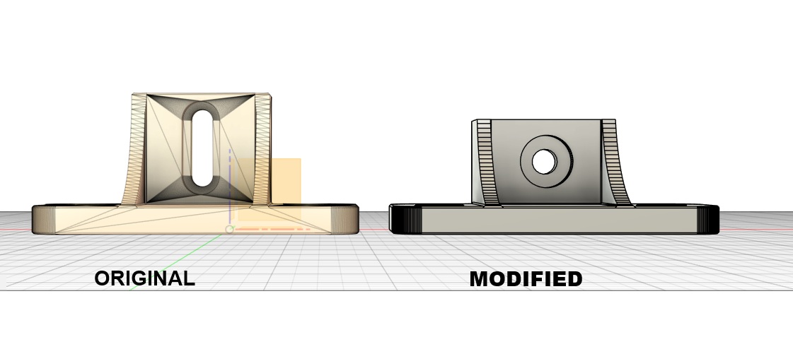
I also modified the 12g to 16g 90* bracket to be 1/2” shorter so that using the calculations from the strut panel for true 48” wide work area can be realized without going any wider with the gantry. The 49” wide MDF will now sit centered leaving 1/2” on each side of the 48” spoil board area. I did not make the change on mine as I had already squared the 48”x60” work surface to the machine… if I were do it again and use the new modified brackets, I would be able to run a t-track on both sides of the spoil board vs. just on the minimum side.
6 Likes
Busy with real work (LOL) not much progress today… did manage to install a backstop on front of lower spoil to match the depth of the t-track bottom (1/8”) which will serve as a stop for the spoil board strips. Maybe tomorrow I will drill out the holes and recessed pockets for the 128 nylon bolts
1 Like
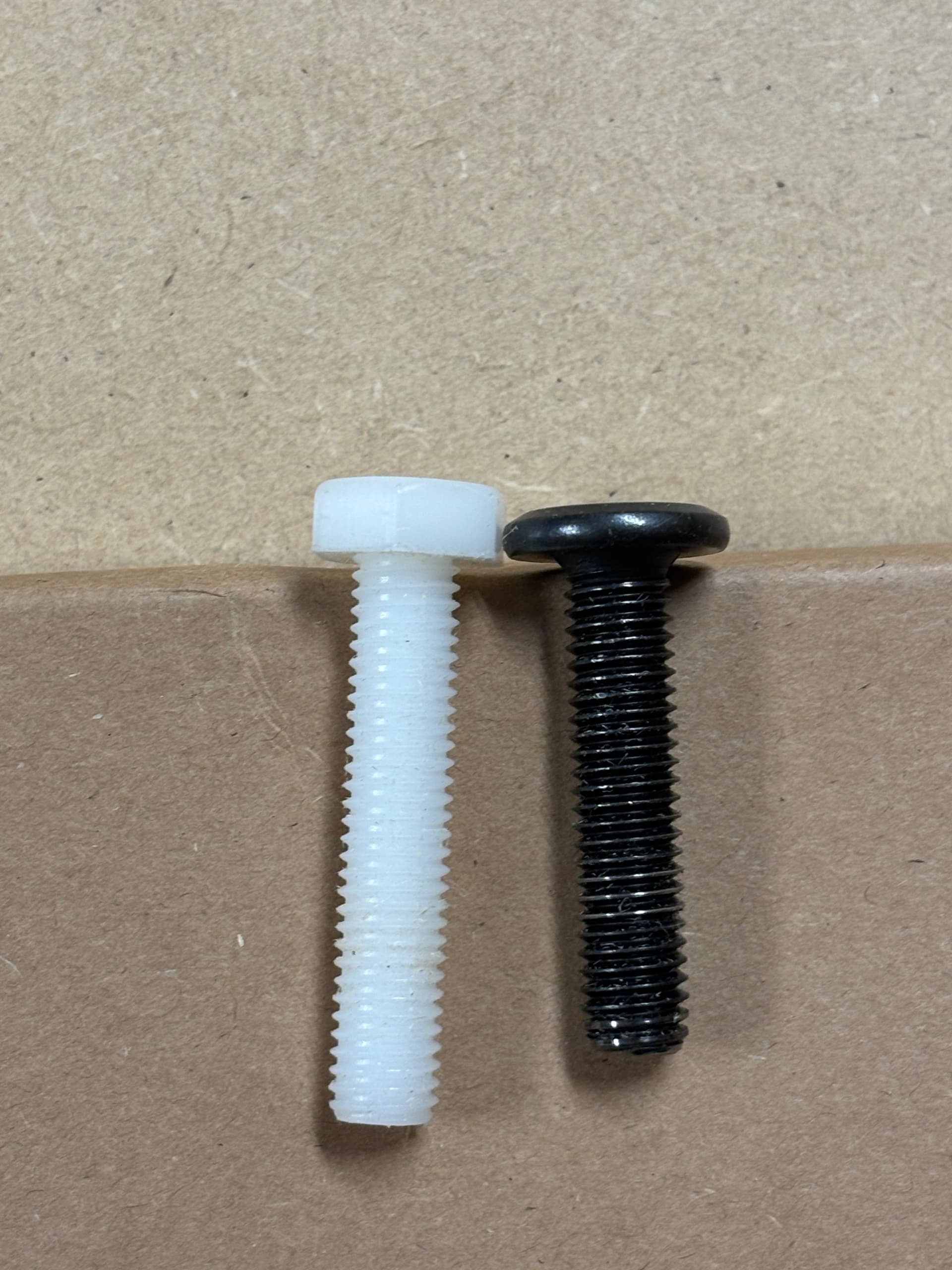
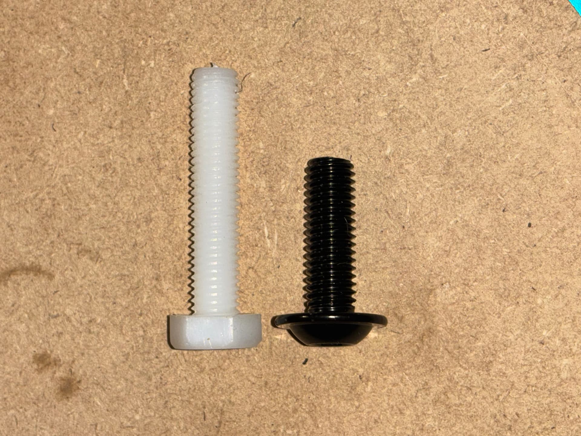
Unfortunately, the new set of now on bolts were made with soft cheap plastic and when I tighten them with my hands to get them snug, they anything beyond that they would strip out so they’re not gonna work
The ones I got a year ago I was able to crank down with a ratchet and they held. They were very strong.
Problem solved, replaced the nylon bolts with flathead hex socket 35 mm in length and eight bolts made of steel, low enough where I should not hit with any tool and they’re able to crank down and hold those spoiled board strips, nice and flat
2 Likes
This looks like a great solution, especially if you’re going into threaded inserts or t-nuts. If you’ve got access under the table, you could consider elevator bolts. They’re like carriage bolts, but the heads are flat, not domed.
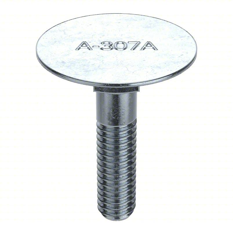
I keep one near my drill press so I can chuck it up as a quick stand-in for a low capacity arbor press. The one I’ve got doesn’t have the lettering.
2 Likes
Designing as I Go - that is an understatement. LOL
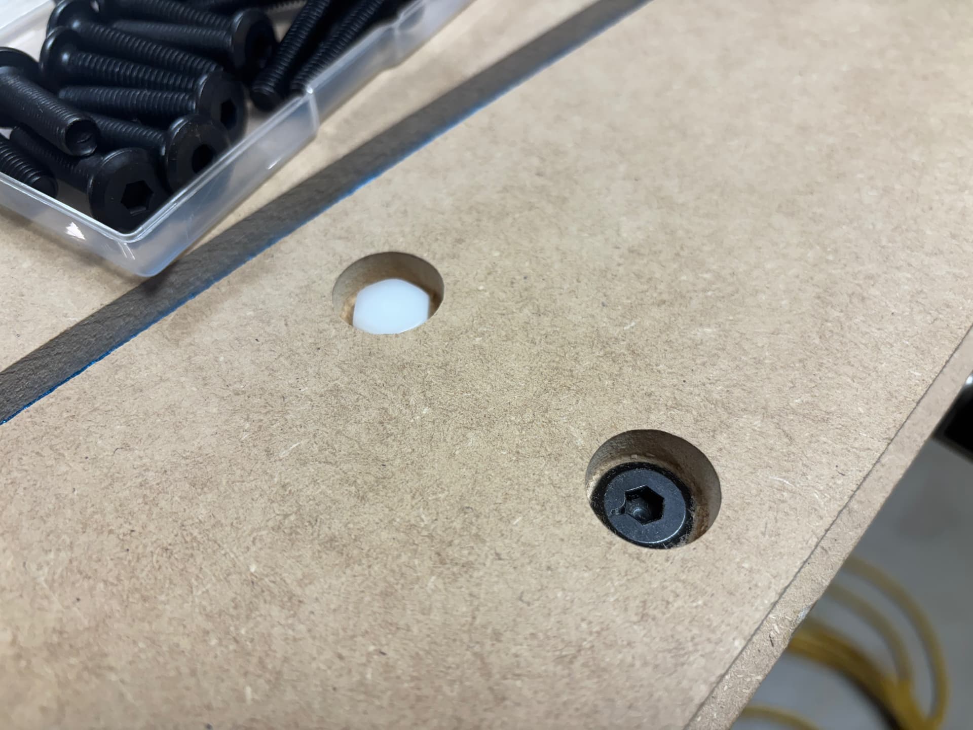
I have changed my mind again… ditching the flat socket head bolts for socket head button flange bolts. The flat heads were crushing the MDF even with little pressure because the heads circumference was much smaller than the 3/4” pocket holes. I found some M8 x 35 flange bolts that worked very well, just shy of the circumference of the pocket… after all this, I surely didn’t want the spoil board bolt to cram through. Probably could have achieved the same effect with washers but this insured the overall height was still at or less than the nylon bolts.
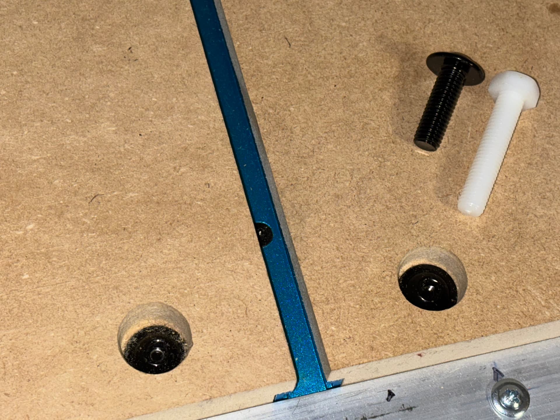
this could have been avoided had I known what to plan for sooner. Initially making the pocket holes large enough for the socket driver to install the nylon bolts at 3/4” to a size more conducive to the flat head bolts would have eliminated the need to use the flange bolts. ![]()
1 Like
so I finally got around to creating the drawings of my table and cut list in PDF format for printing on 11x17 US Tabloid Size paper.
here are the links
4 Likes
Peter - Thank you for posting the drawings for your table! I really like this design and I’m planning to do something similar for my upcoming build. I had some questions for you if you wouldn’t mind clarifying a couple things:
For my half sheet (4x4) build, I’m planning to use 49”x97” MDF stock for the tabletop and want to be able to cut half size plywood sheets all the way to the edge (full 48”x48” work area). I see on your drawing that you have sized the half height strut that carries the tabletop and spoilboard to be 58” long and that you have the 49” tabletop offset to one side with 4.25” space to the outboard strut on one side and 1.5” space to the outboard strut on the other side.
- With this layout, are you able to cut a full 48” width? How long did you need to cut your X-Rails? For example, if I plug in 48” into the calculator for usable cutting width it says cut the X-rails at 54.625. Is this what you used for X-rail length, or did you plug in 49”, or did you custom size the X-rail length to match your outboard strut spacing?
- How did you arrive at the 1.5” and 4.25” offsets? Is there a schematic somewhere that describes the relationship from the spindle to the outside of the x-carriage, or just a general layout of the x-beam relative to the y-rails?
- What about the length? I’d like to just cut the 10’ strut in half for my Y-rails which would yield just under 60” in length. The calculator says I need my table to be 60.375” for a 48” work area. Am I going to come up short or do you get a little bonus length from the uni-strut rail approach?
- Any regrets or lessons learned from your build that you haven’t already mentioned?
Thanks in advance!
Happy to help (if one dares to call my knowledge and experience help. LoL).
- In retrospect, I would make the width of the half height supports about an inch longer than I did and set the rail side first then the non-rail side based on your gantry. Then if you built the gantry correctly, it should move the full 1219.2mm or 48”. Once your (and I used a 1/16” bit) bit is at X1219.2 and Y0, i made sure the corner of my work area was 1/2” off the rail edge and 1/2” off the front. Theoretically this will give ‘you’ a 1/2” margin all around the work area on the 49” x 49” spoil board. The wider half height supports being an 1” longer than I did gives you the ability to adjust the spoil board to be dead on the range of your machine… assuming it was also already square.
- I took those measurements from my original full size 4x8 wooden table… but after doing so, I realized so long as I made the half height supports wide enough, i could (using the redesigned 90-degree brackets) adjust the distances as needed so those measurements just ended up being just a starting point)
- I too used the calculator and cut accordingly. You will need two 1” EMTs. One to cut the two X rails and the other for the Y rail. Here again, I would have preferred to have an extra inch on my Y rail as the bearing wheel when router is max X and Y is about 3/16” away from the edge of my EMT. It has never pushed beyond that point (doubt it will) but still would have felt better with a bit more road there.
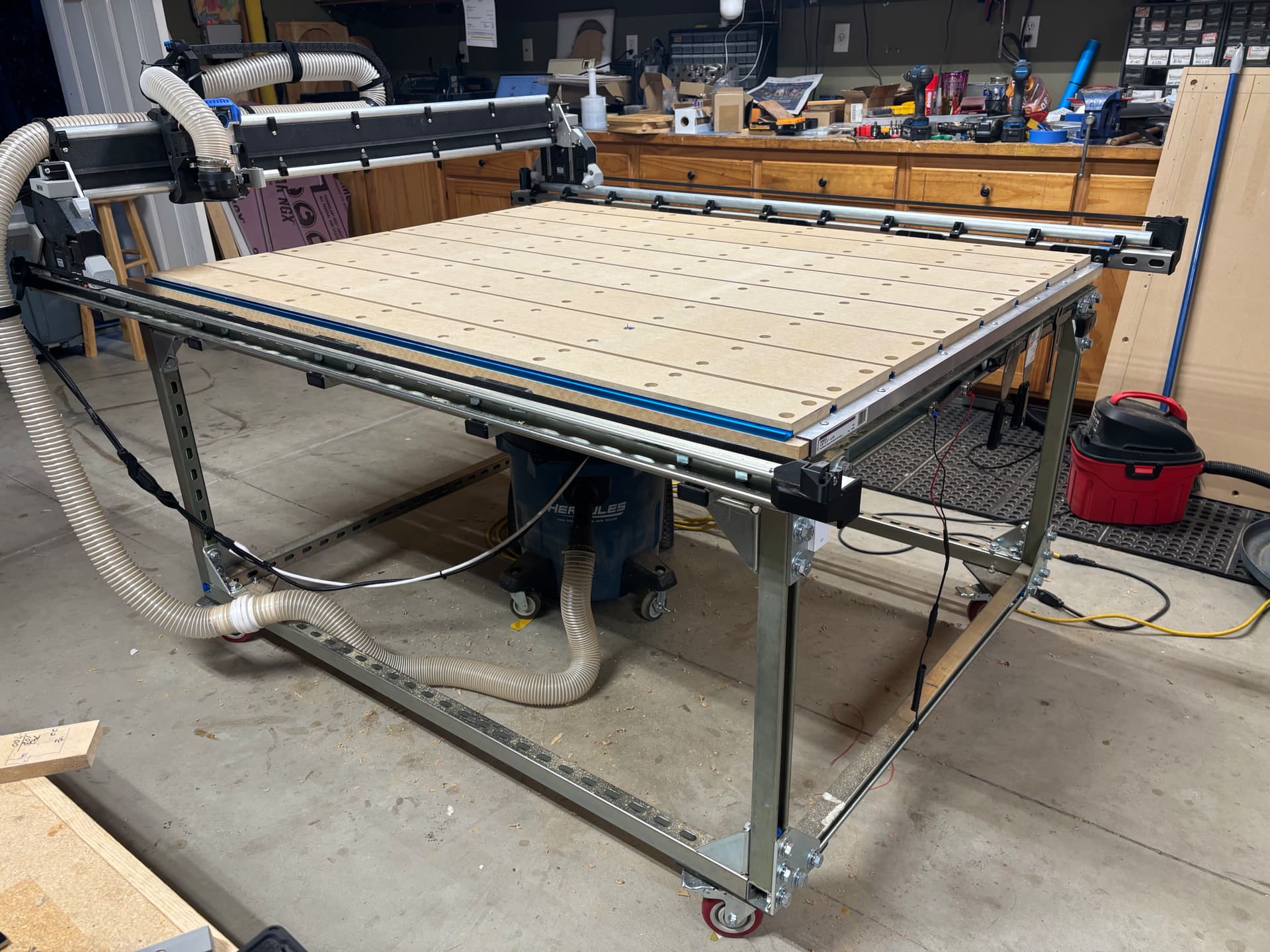
- If you plan on tucking your dust extractor under the table as I had intended, you may wish to first insure it will fit before settling on the height of your build… mine was just a bit too low as I planed on setting mine on a “shelf”, however, I had to settle for it freely rolling around underneath but it does achieve the goal of not having it stationed elsewhere.
Good luck on the build. It was a fun and expensive project. But well worth the effort. ![]()
5 Likes
Thanks for this @ttraband ! Didn’t know about these, just ended up ordering some for a printed based project where I want low profile and bolt to be captured. Cheers!
3 Likes
I was happy that my original torsion box full sheet table top did not go to waste. Scott pick it up on Saturday. I hope he gets lots of use from it while he builds and uses his future LR4
5 Likes
I love my new unistrutchannel table. Just saying. So portable. Only thing that is not free to roll is the power cord I plug into the wall to run it.
Currently I have wireless on/off switches for the router (which also triggers the dust extractor that rolls around under the table) and similar for turning the machine on and off. I might hard-wire these now that I have a more permanent table/machine. I finally have gotten used to using the WebUI on the Surface Pro (pick up one from amazon refurbished for like $100 and it works flawlessly).
We had a power outage and I guess the ip address changed so I used the local wifi address and learned I could simply download the file I created on my workstation saved on the cloud storage directly to the micro sd card using the WebUI… typically I would d/l it from the workstation then walk the sd over to the machine/mb. Always learning says I.
13 Likes
That turned out really nice Peter.
1 Like
Looks really nice, love that table
1 Like
It looks amazing!
1 Like
I’ve always liked things built with Unistrut. Lots and lots of fixtures, power distribution, jigs, etc have been made with the stuff.
2 Likes