I am finally getting around to posting my build process. It was a lot of fun. Perhaps one of the best projects I have worked on. I will break the journey down and include some photos. I am still not across the finish line (and I am hopeful this group can provide some guidance but I will save that for a later post in Troubleshooting).
I was resistant to the LR4 because I started my CNC hobby with the Foxalien Masuter 3. I had lots of success when I used it with the laser but several builds were interrupted with skips, etc. I blame these mostly on the 6mm belts and the small stepper motors. It would mess up when I did not manage the dust well and the belts would get chips in them. At that point the job was done for.
For this reason I was looking for CNCs what did not use belts. This forum convinced me that I would not have the same issues (or at least not as frequently) with the LR4 design.
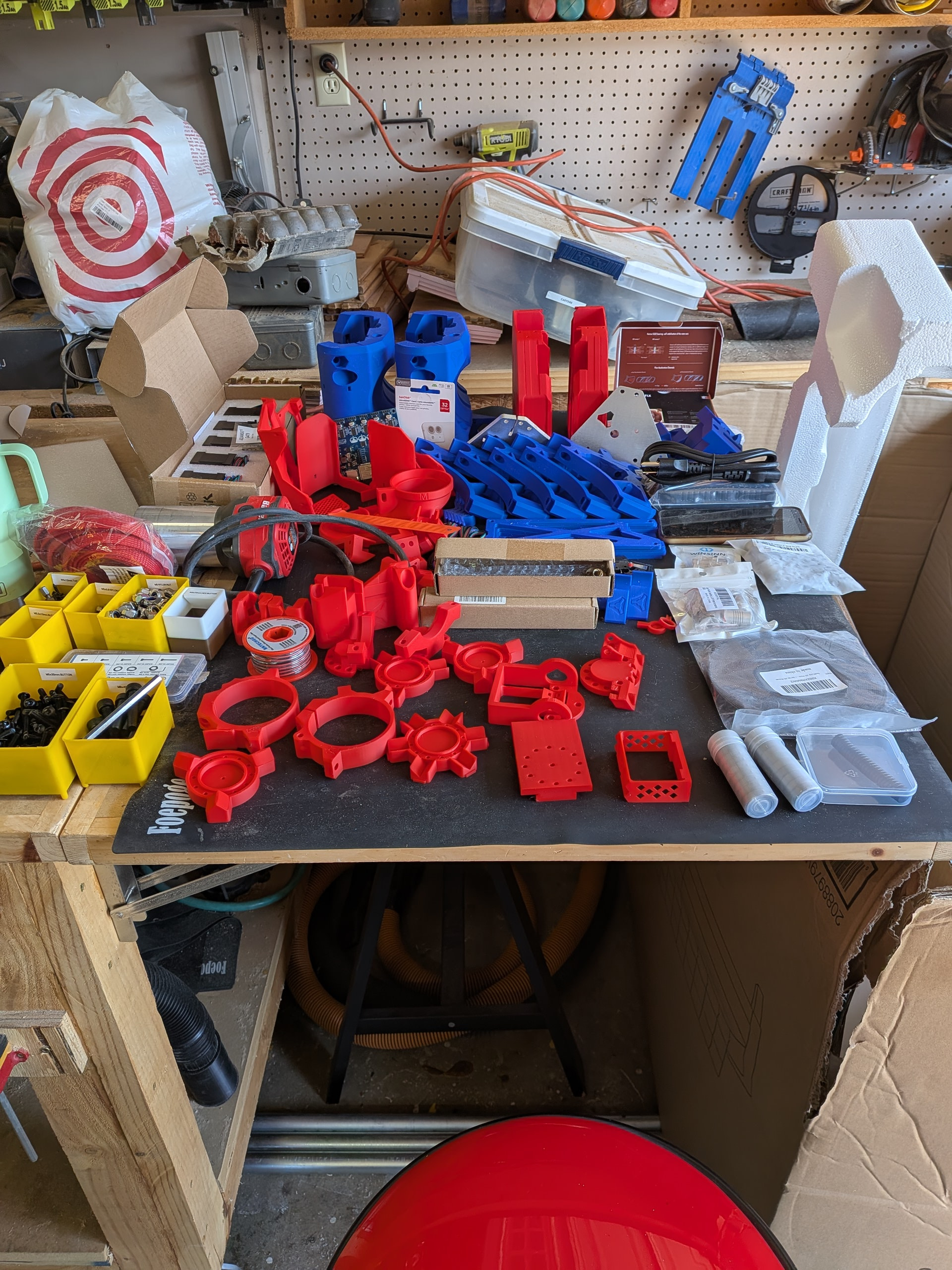
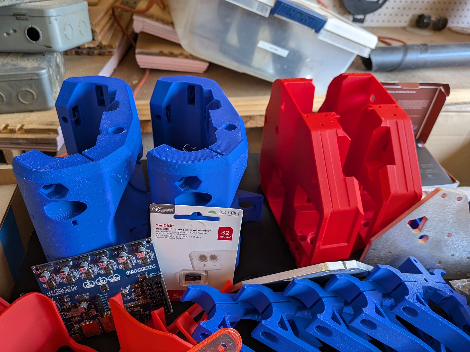
So, I jumped in. I bought some parts from V1E (aluminum plates, Jackpot 3) but I gave my family the opportunity to gift me the other hardware parts for Christmas 2025. I already own a Bambu P2S so I wanted to print everything else myself.
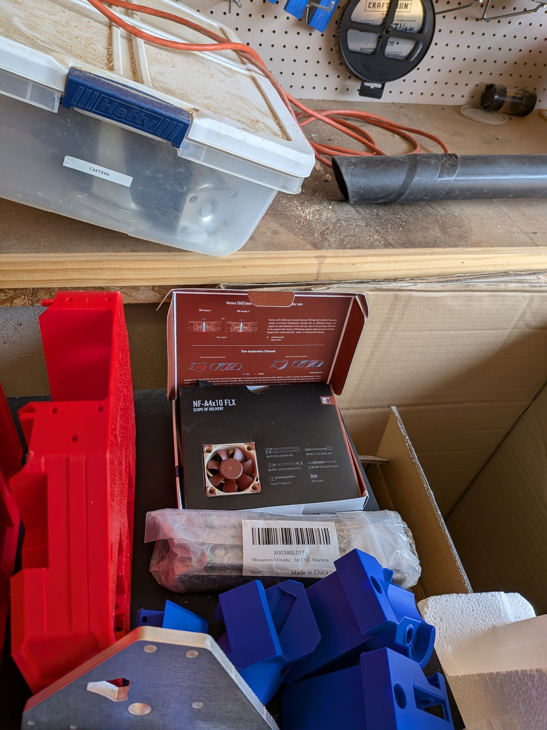
I decided to start with a cooling fan (although I am trying to stick to the Yellow Brick Road as much as possible. Some enhancements seemed easier at the start and do not appear to just put me on the shoulder of the YBR rather than onto another path
Yes. That is two cores. Even though I had never done inserts in my 3d prints I decided to go with that version after I had already printed the original core. I was successful with the inserts so I am using that core.
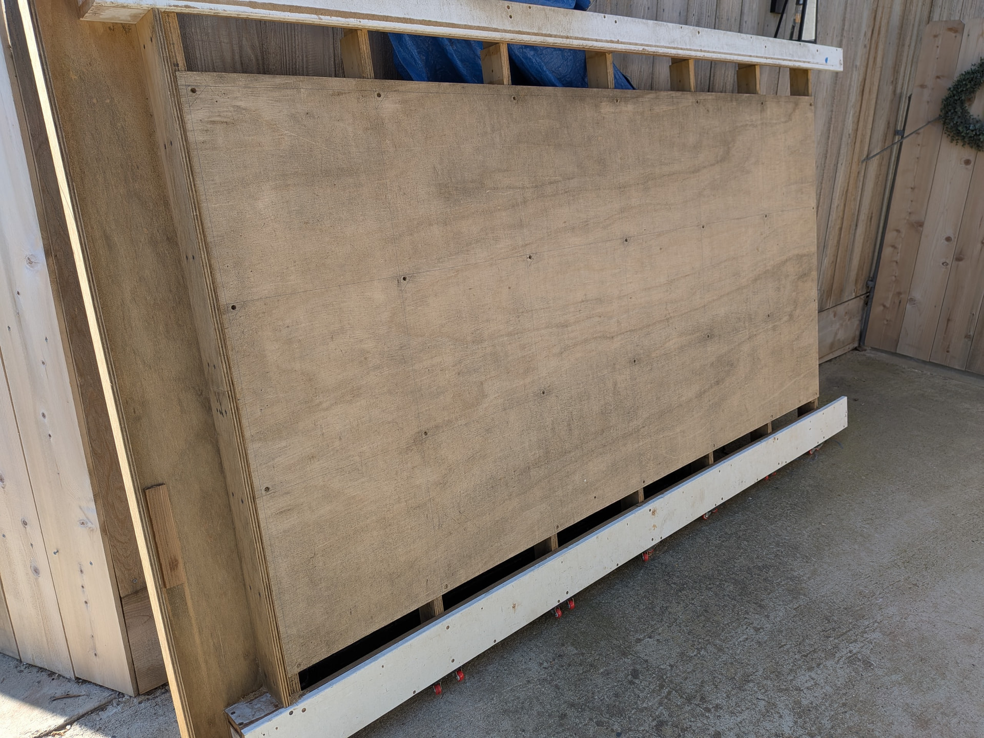
My ultimate plan is a table that is 3x4 or 4x4 but Peter @HyeBuilder posted that he was giving away his original table and he happens to live about 45 minutes from Fresno. He was kind enough to give it to me. This lets me get things set up and use the LR4 for a while without building a table (or working off the floor). The table it probably too big for my garage shop unless I incorporate my table saw and router table (which may happen eventually).
Also, I did to realize at the time I met Peter @HyeBuilder but his videos were part of what convinced me to move forward with the LR4. I didn’t realize that until I got home and started rewatching his build videos and saw his red Ford Mustang in the shot. At that point I realized I was in his garage and saw the cool new table he built with unistrut.
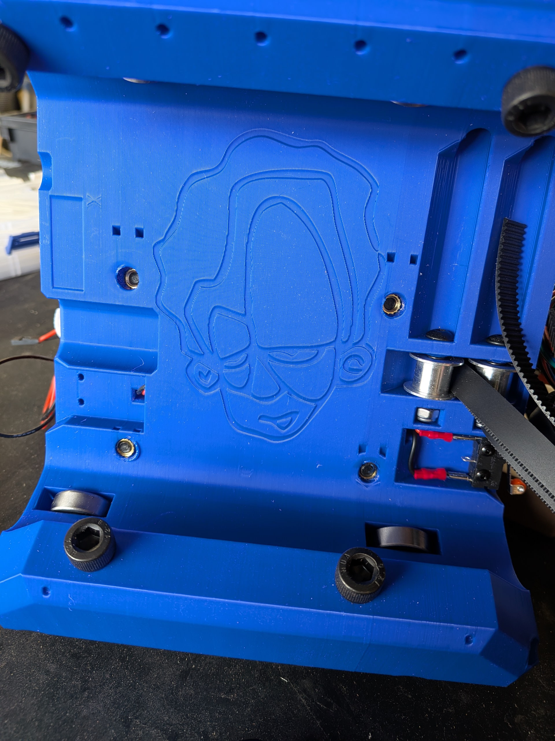
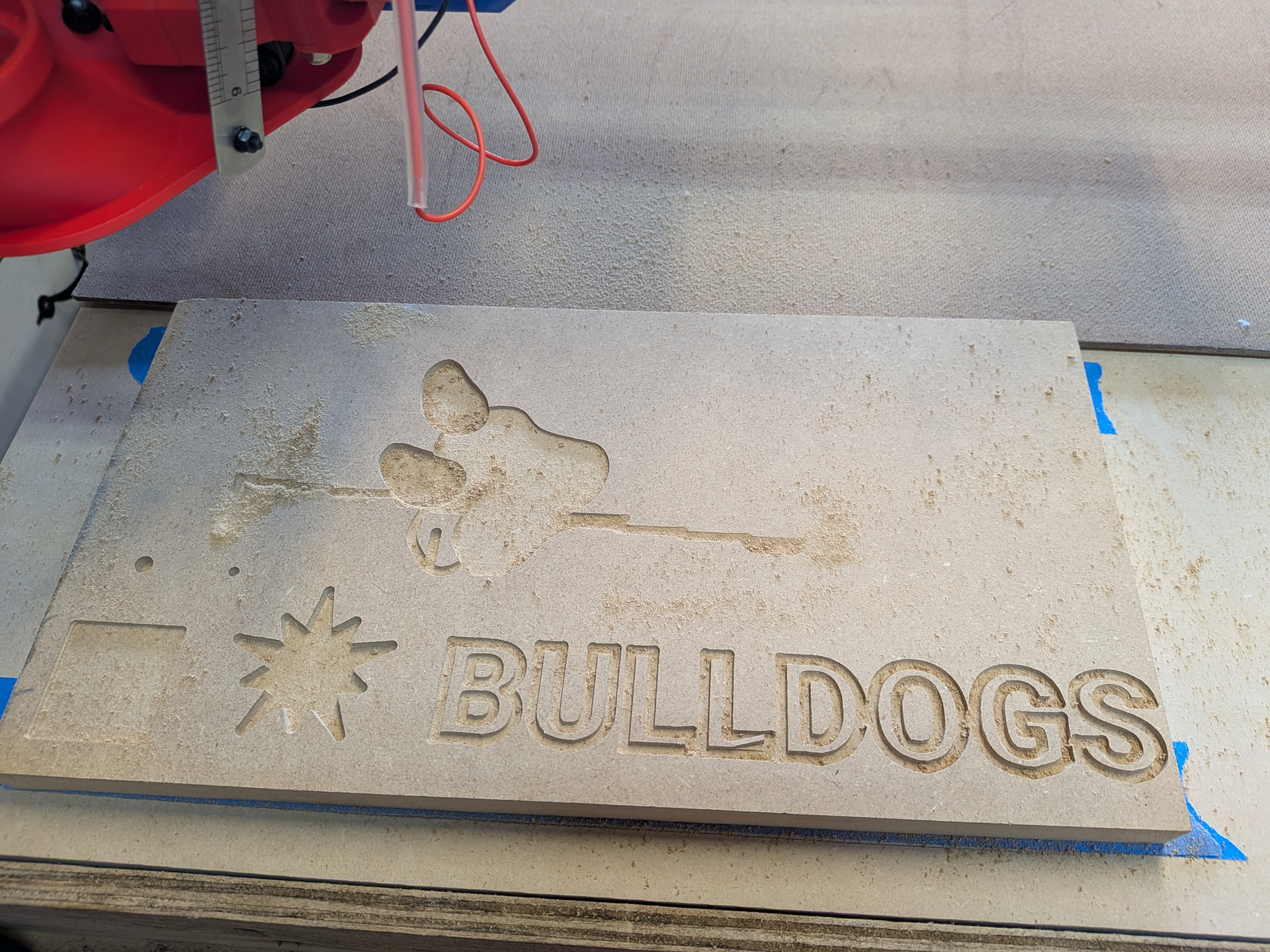
BTW - I am in Fresno, California and teach at Fresno State. We are the bulldogs so, therefore, the Bulldog Edition with school colors (although I would use a darker blue if I had it )
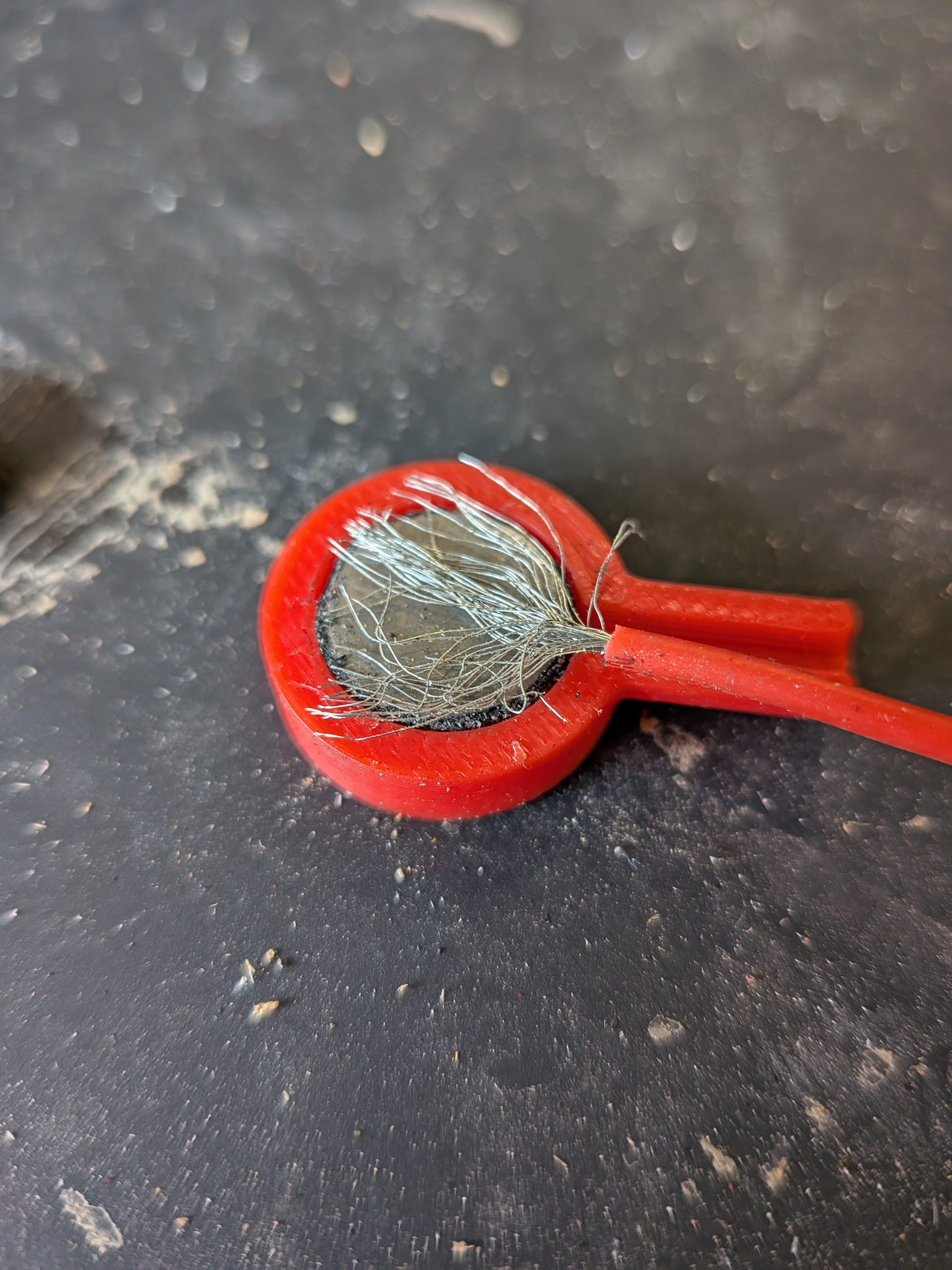
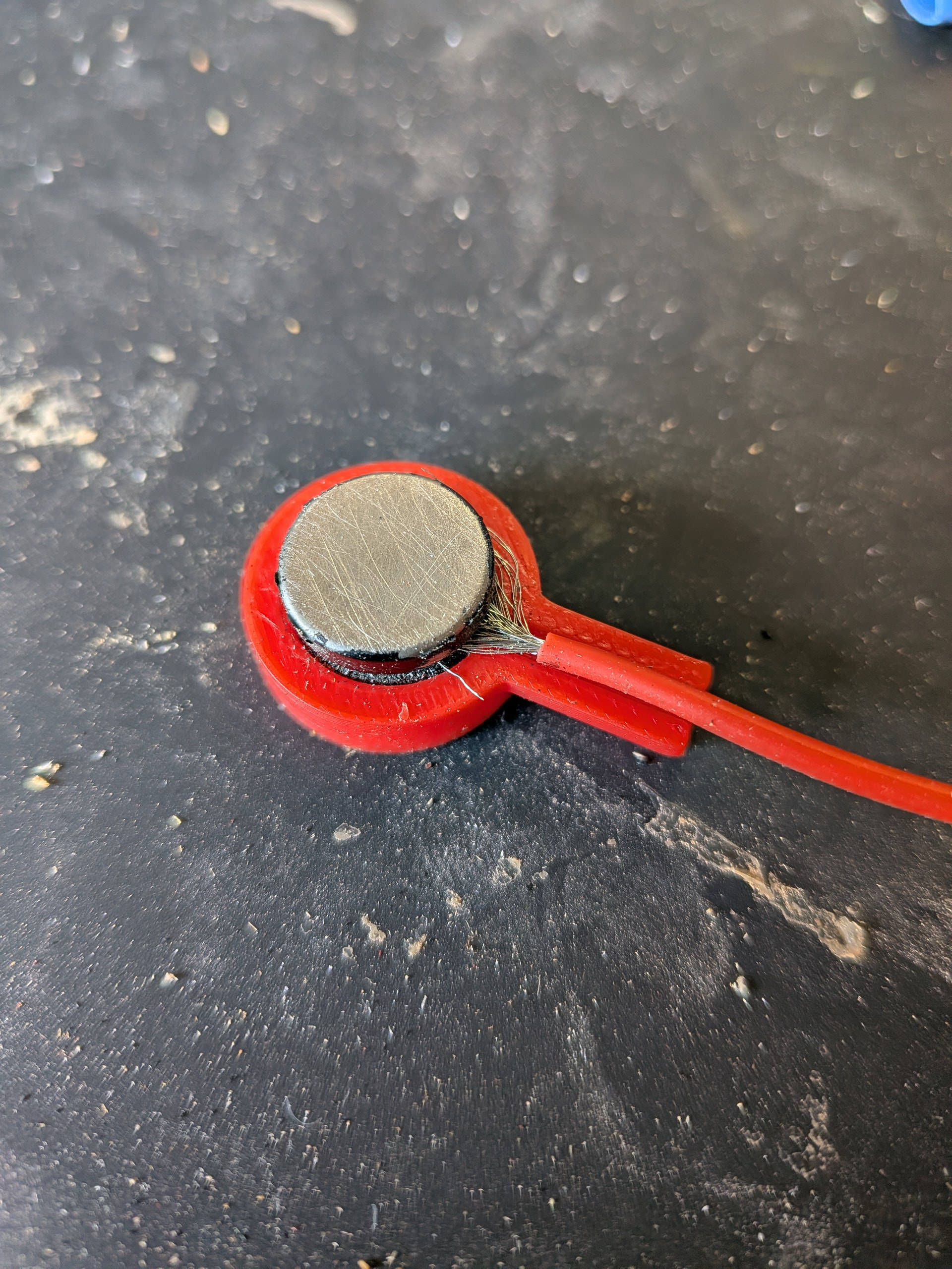
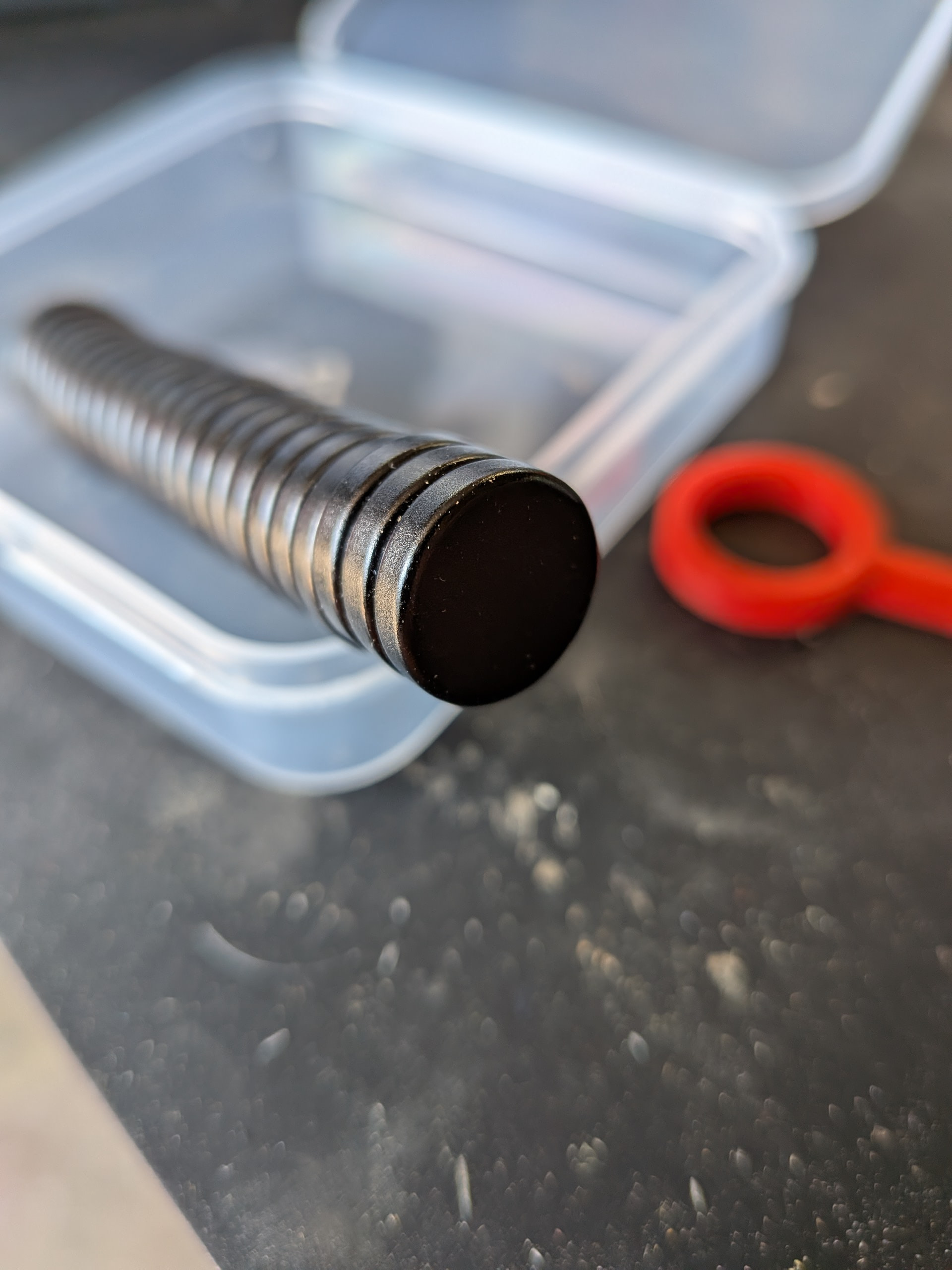
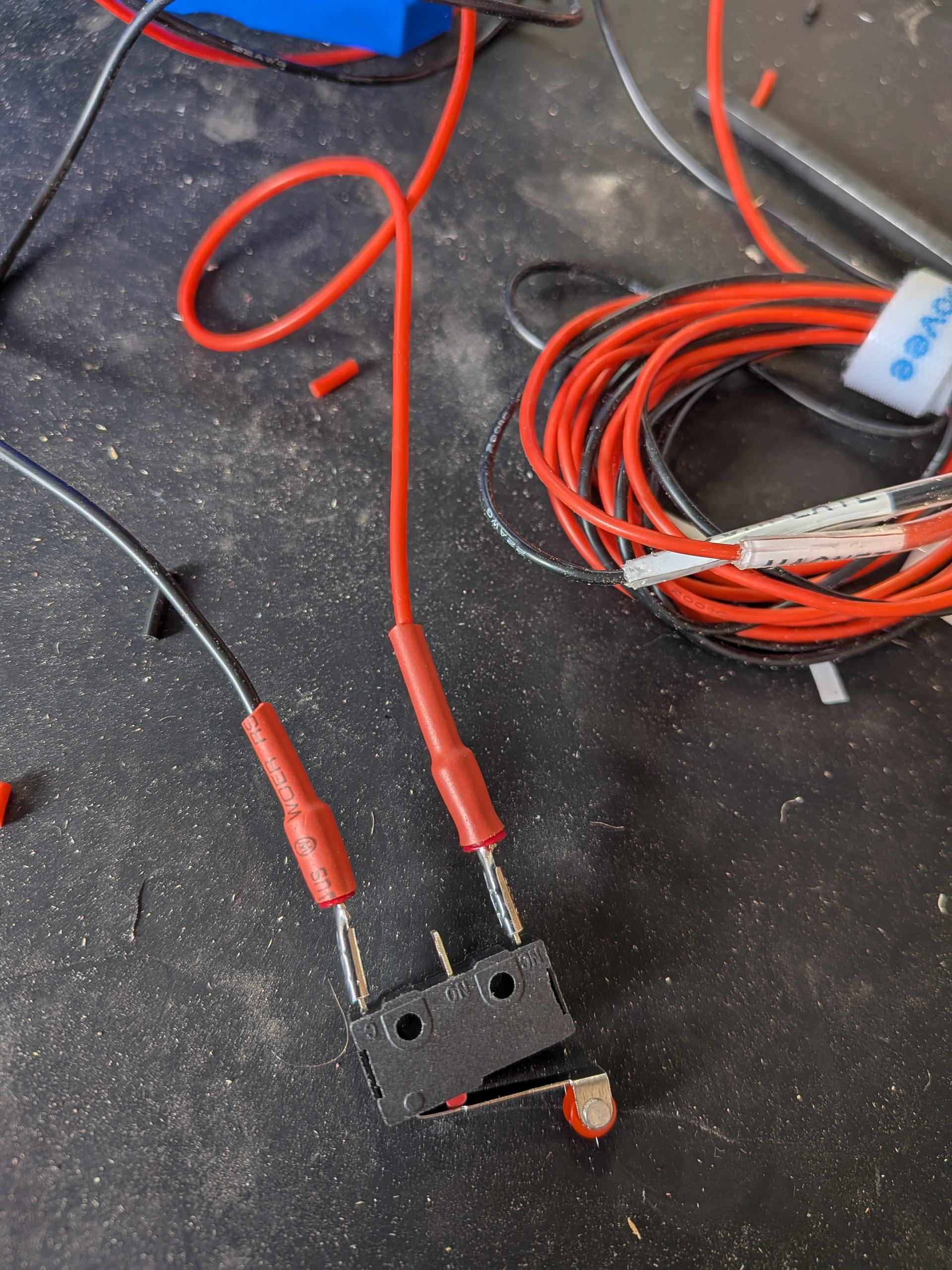
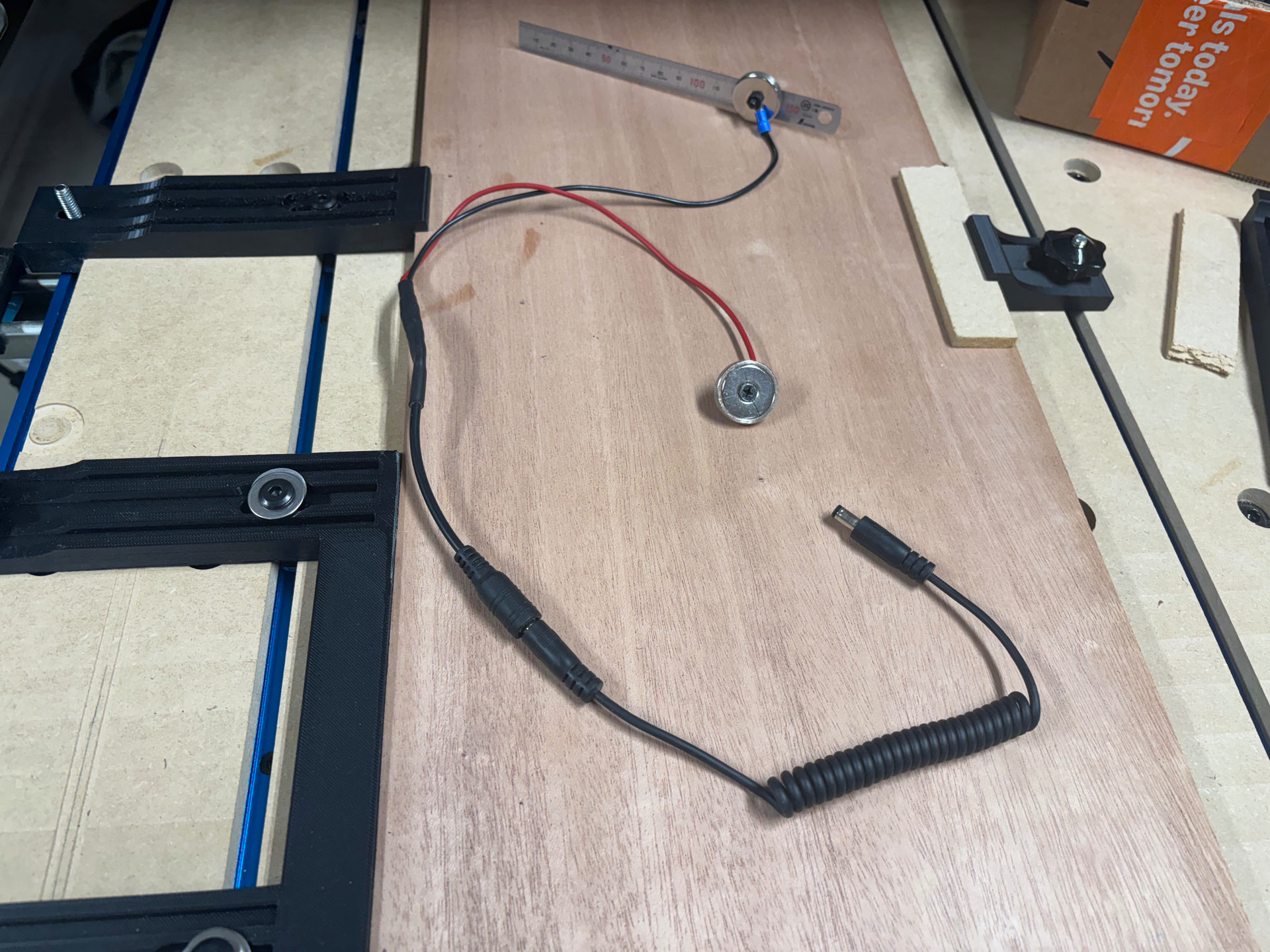
I also went with @DougJosephtouch plate system. I always wanted a magnetic connector on my Foxalien so I went for it. I was unsuccessful soldering the lead to the magnets but I got it together. The problem was the “cool” black magnets I purchased. I ended up having to scratch off all the paint to get the current to flow. I also had to sand down the magnet side of the holder because my magnets much not have been as thick as those he originally used so they did not stick proud out of the print. I could have reprinted but decided sanding down the plastic to bring it flush to the magnet was fine. I frequently tested to make sure I had continuity and that the result would attach itself to the router nut.
I reinforced the connection to the magnet base with shrink tube. It actually is holding up better than the stainless steel ruler side. I had that connection disconnect once but beefed it up the second time around.
Congratulations on the new build. It looks great. The kinematic tool holder will come in handy if you decide to add a laser to your LR4. Looking forward to seeing what you make with it.
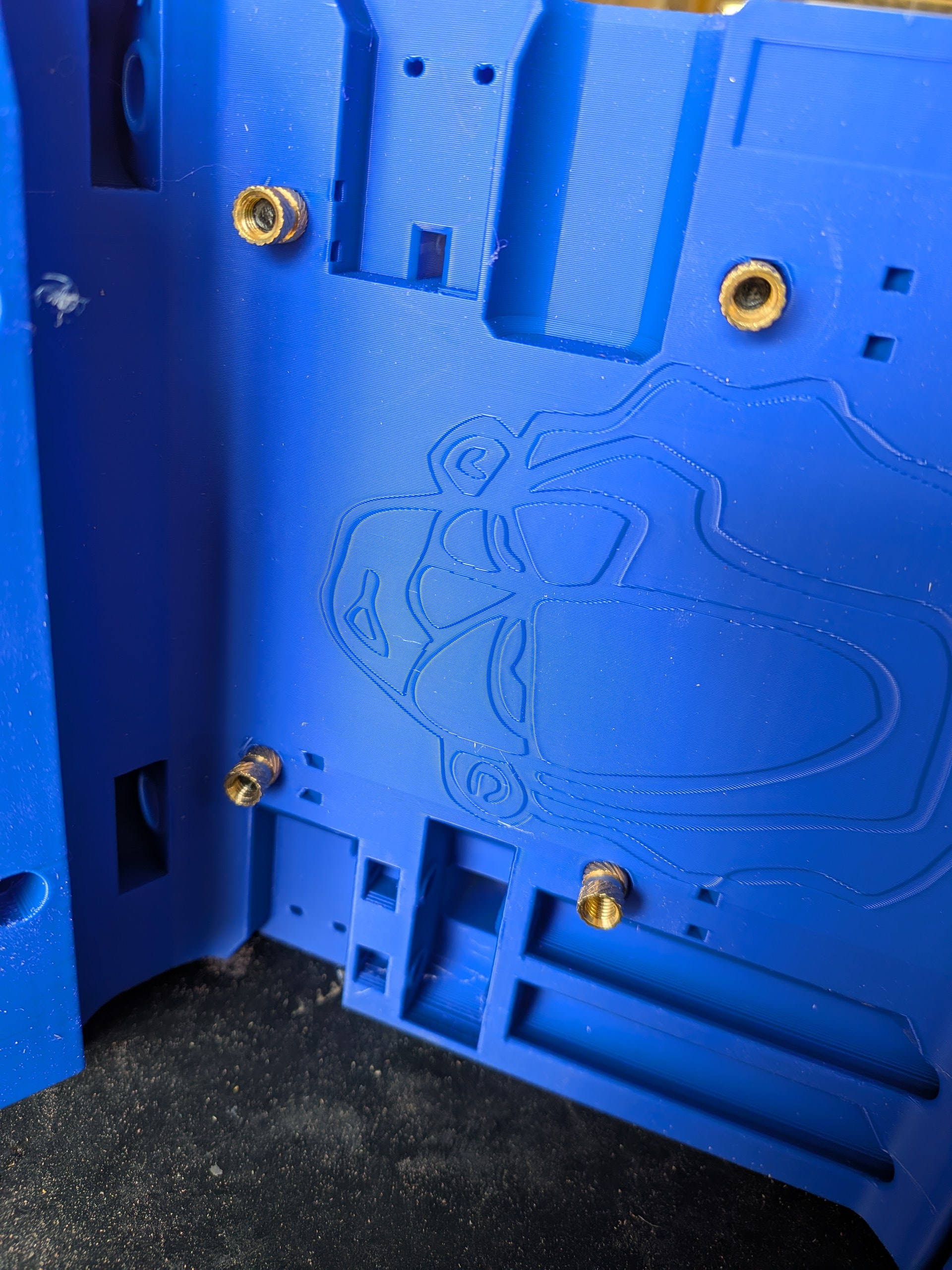
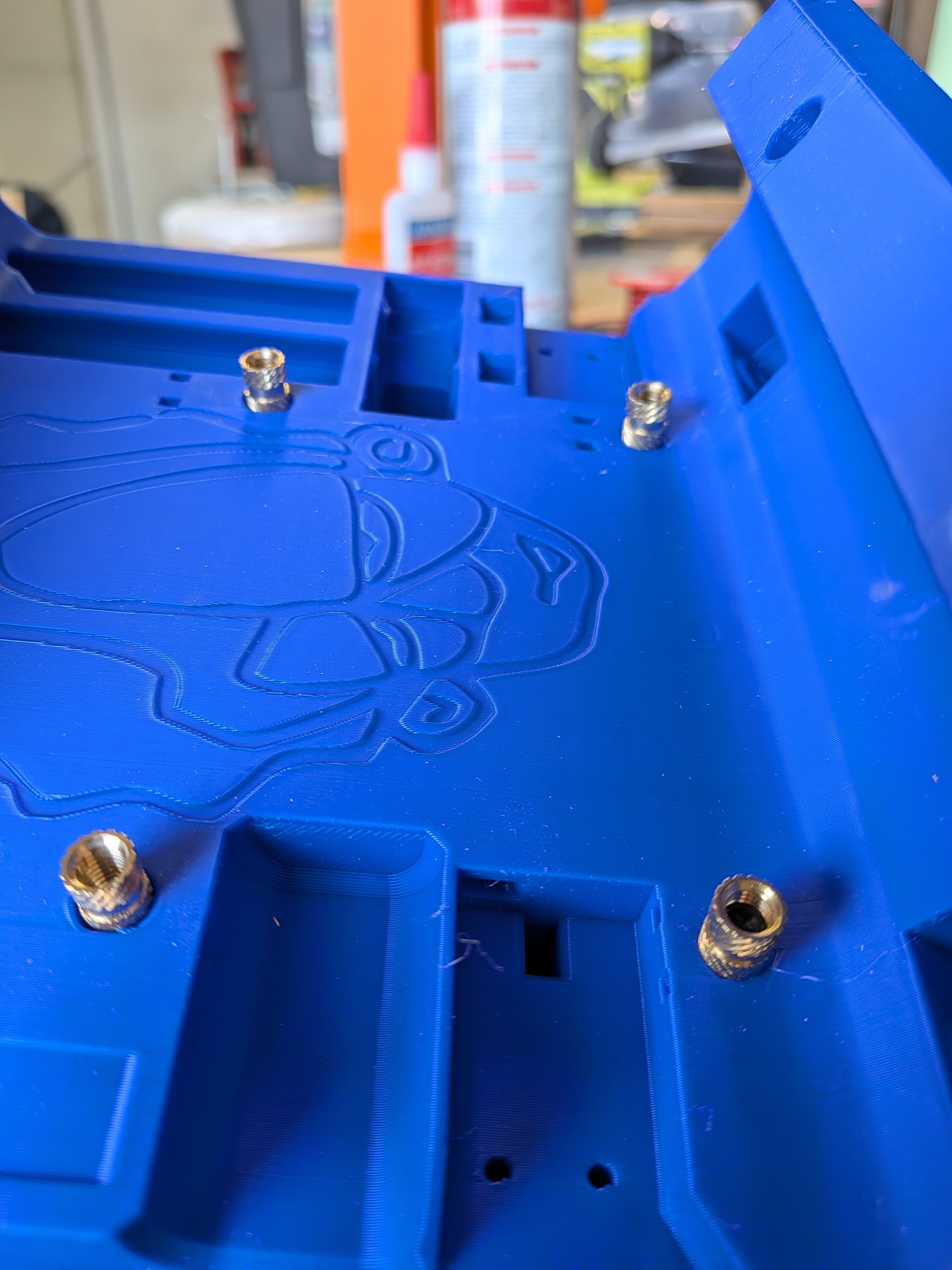
I decided to try my hand at the threaded inserts first. I figured that if I screwed those up I had not wasted too much time with all the subsequent steps.
Someone suggested putting the bolt through to guide the insert straight. I did that. Used my soldering iron on the insert and pulled the insert into place by tightening the bolt. Worked great. I took my time. I was not sure if I could pull the insert too deep and mushroom out the hole so I did not get overly aggressive tightening the bolt.
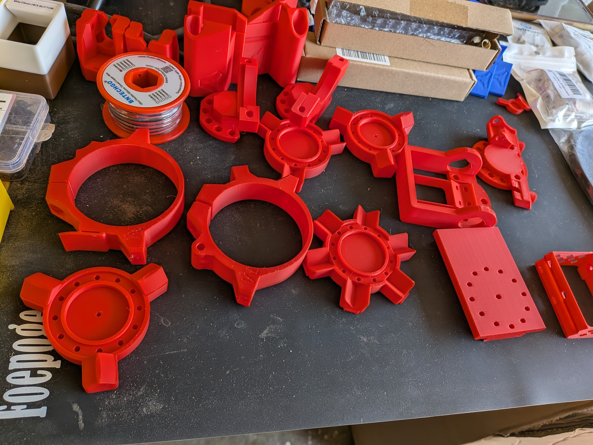
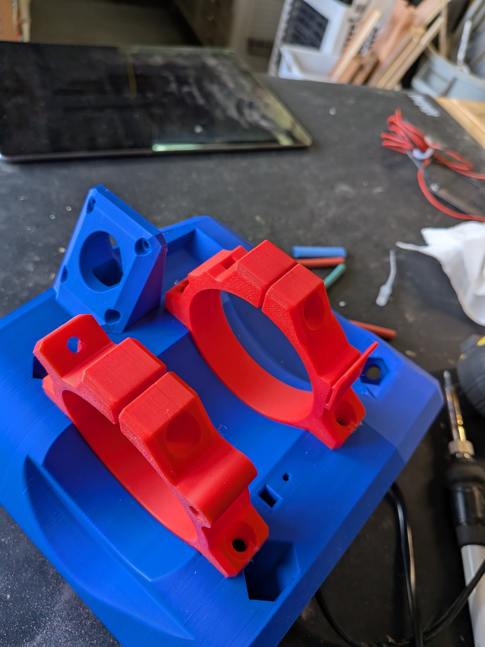
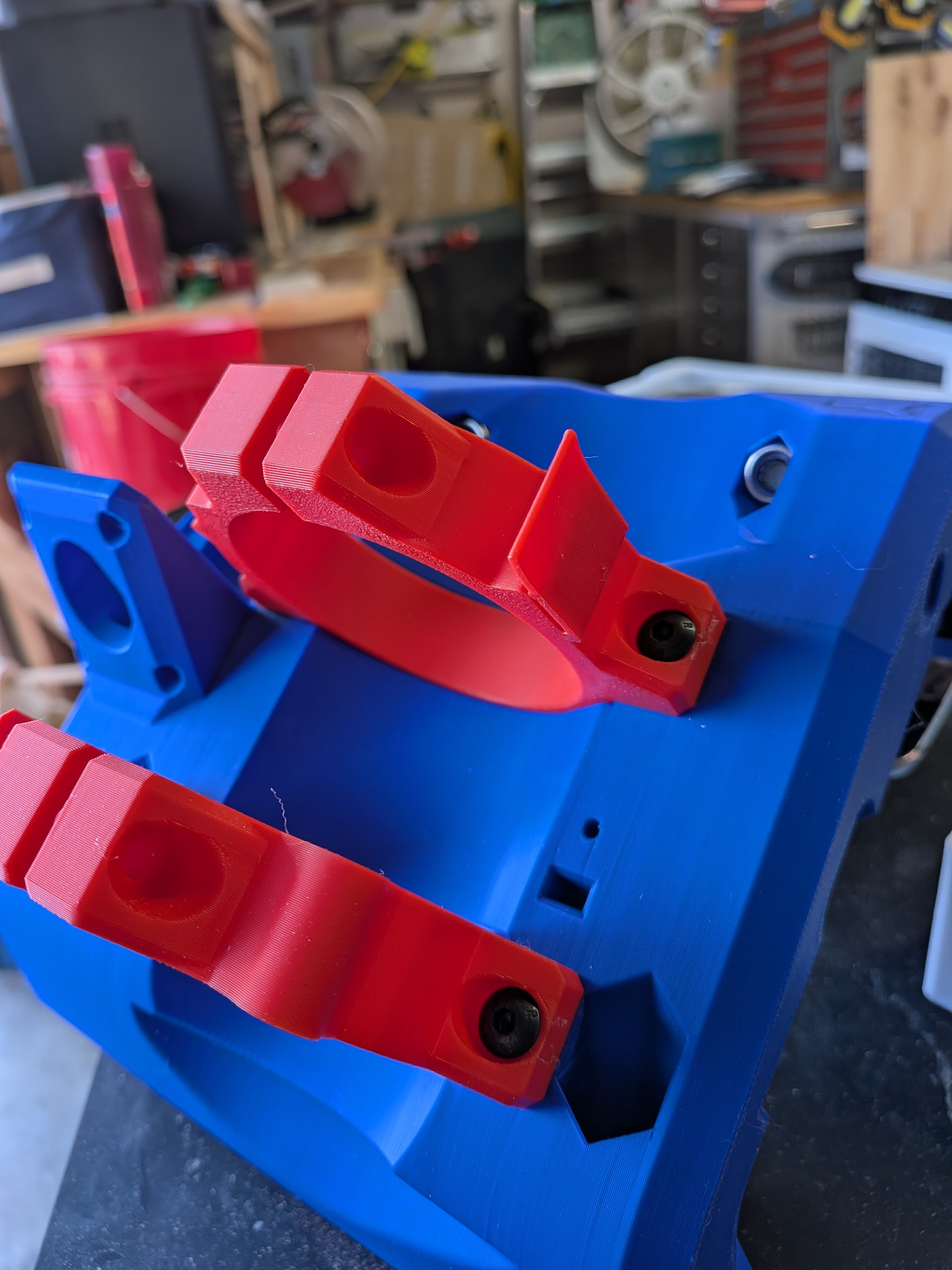
I let those cool and then tested the fit of the router holder. I originally printed the 65mm router holder. I believe it indicated it was for the Makita but I am using a HFT Bauer router and those were too big. I found someone had posted a different set with a dust shoe so I printed those and they work perfectly.
I got the bearings put in place. Everything went together just like the directions and the videos.
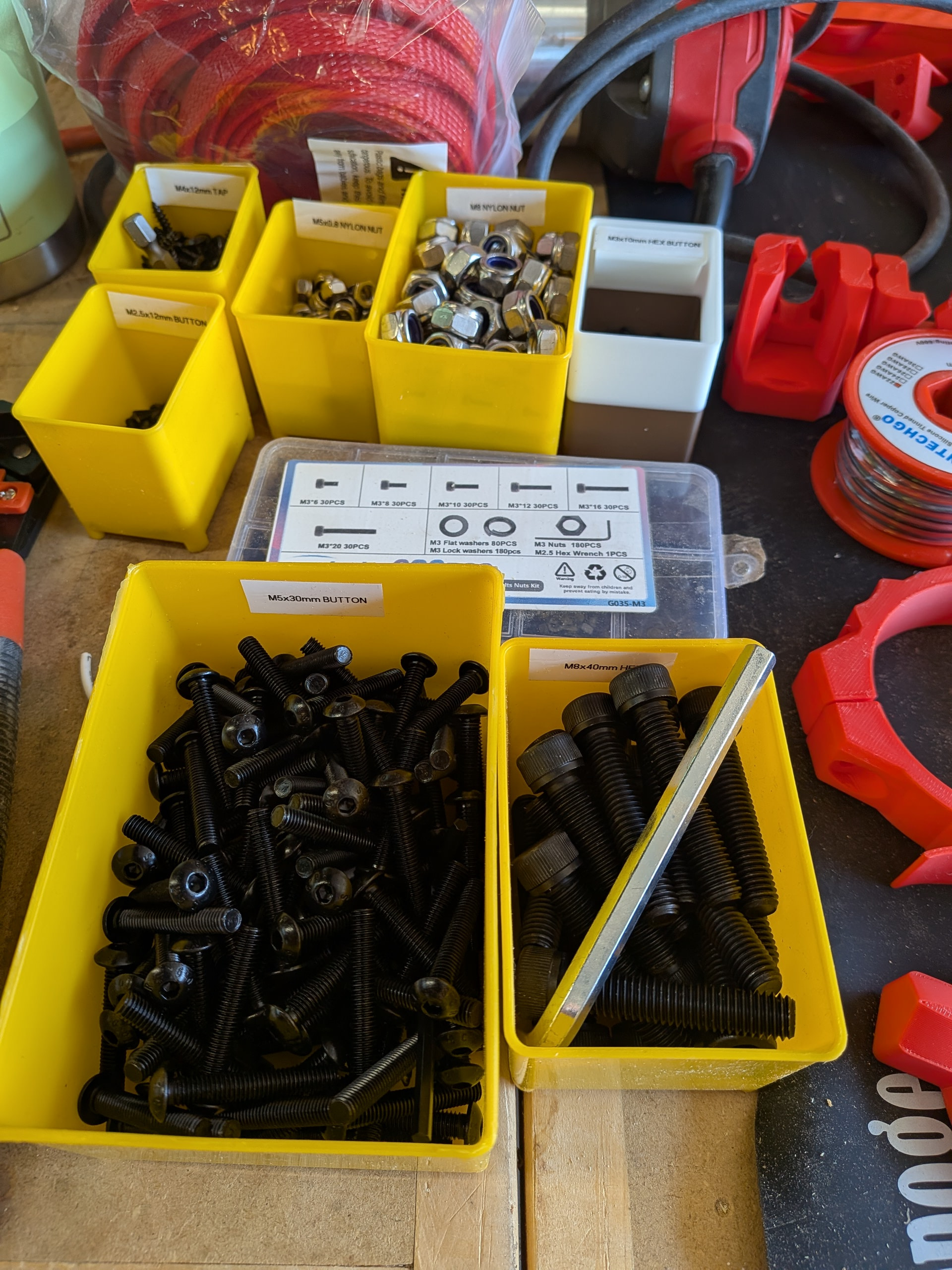
I imagine I am not unlike others that struggle early on with the anatomy of the machine. The directions use a part name and I found myself often searching through my pile of nuts, bolts, printed parts to find something that fit or something that looked like the picture. Later you figure out what each part is for but this comes with time. An idea for future versions would be to place some distinguishing number or letter on the parts to make finding the correct part a bit easier. Also, not all the steps in the direction specifically mention what size bolt, etc. is used. This becomes more obvious with repetition later but it is intimidating early on.
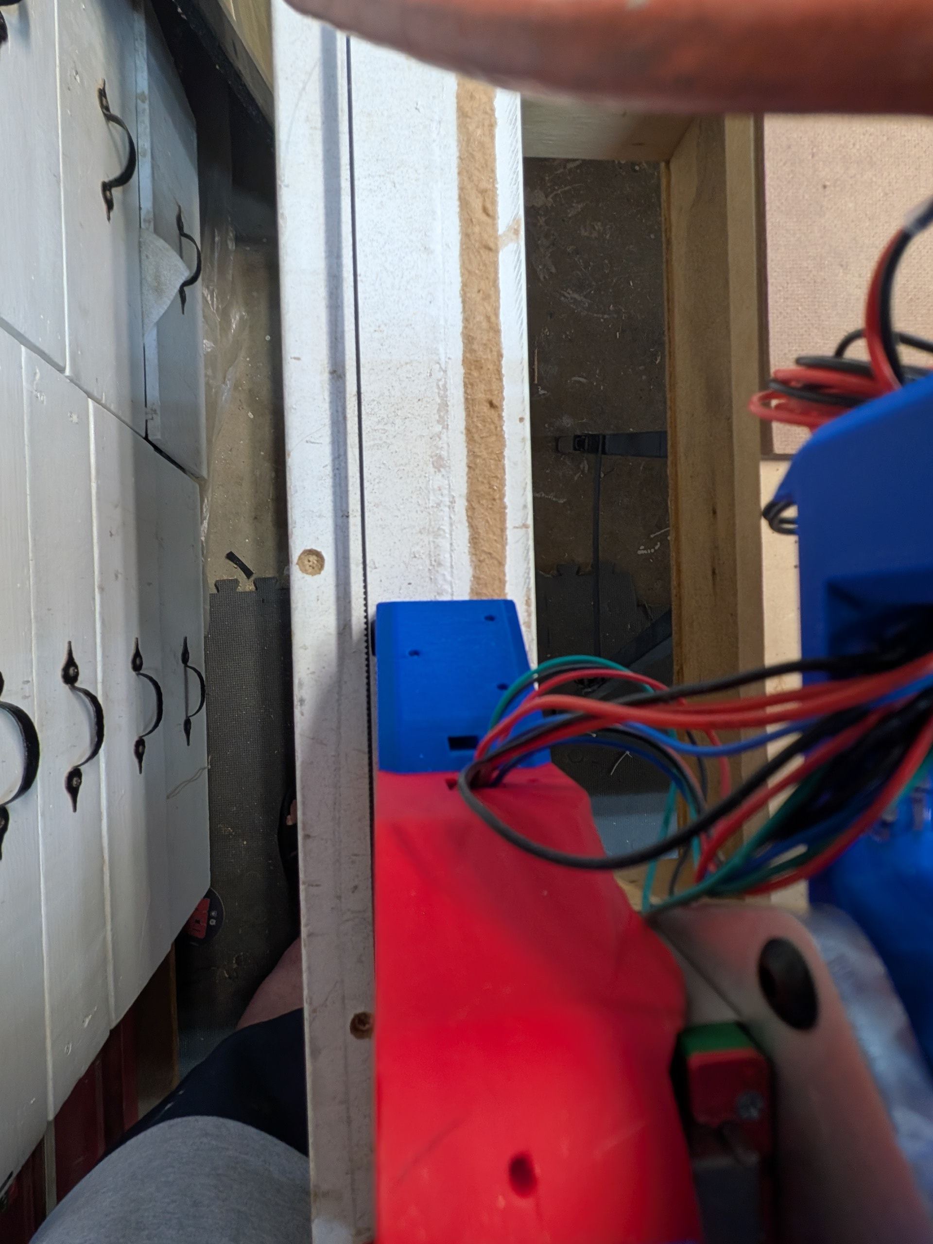
Time for wiring. I was certain at several points throughout this wiring that I was not going to be able to thread the wires through the slots - BUT, the engineering on these parts was flawless. I moved forward in blind faith and the wire always seemed to come out where it was supposed to come out. I was amazed. This went together so much better compared to lots of store-bought manufactured items I have assembled. Thanks to the team and @vicious1 .
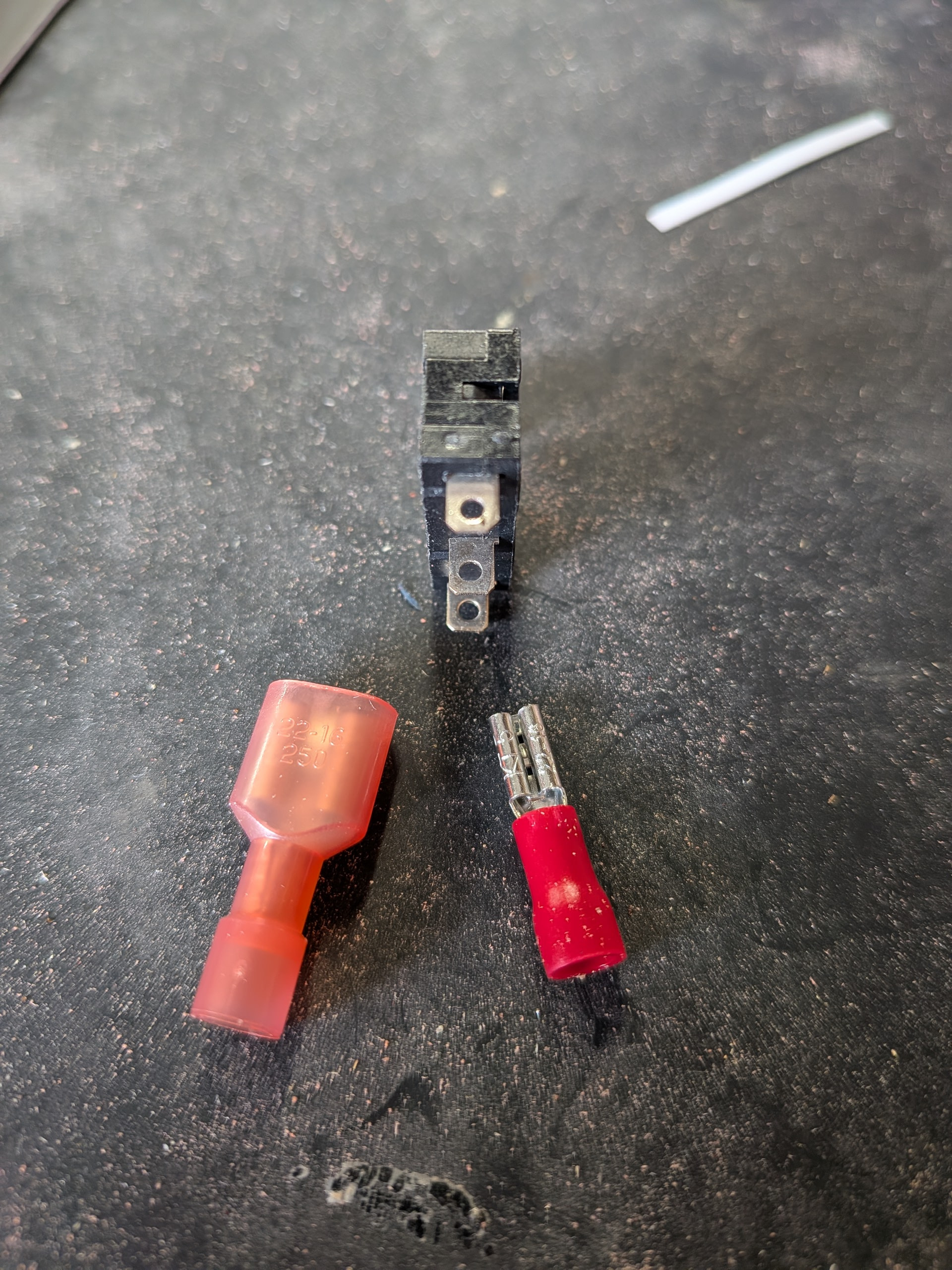
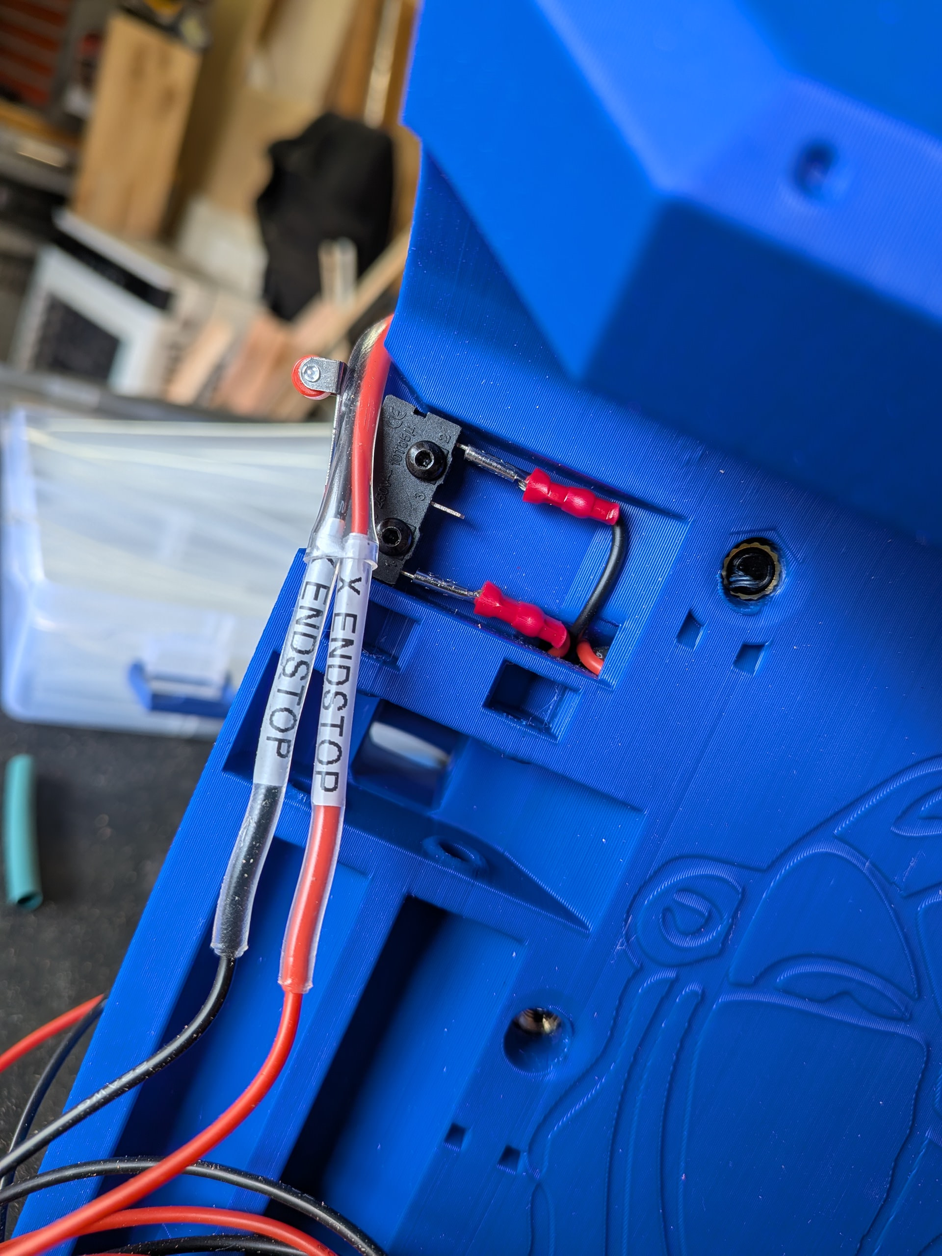
First I encountered this. The connectors I had, which are easily available at big box stores, are 1/4”. The endstops needed .11. Nothing that Amazon couldn’t get to me by the next day. Then I proceeded.
I made sure to label my wires. I thought I would get fancy and use some clear shrink tubing to hold my Dymo labels. Careful that you make sure you can fit them through the tunnels before you do this. It worked for me but I would probably wait until I had routed it through next time.
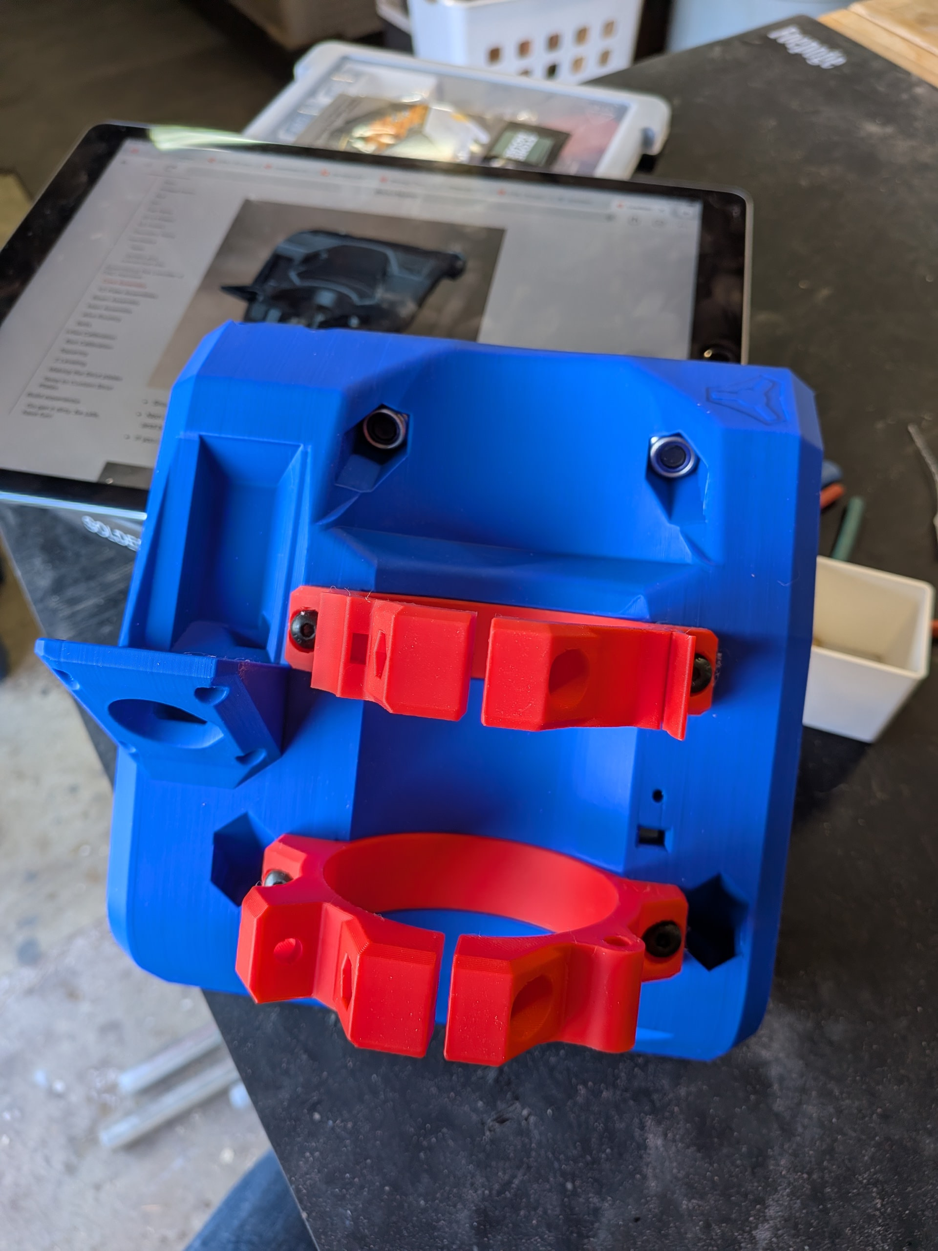
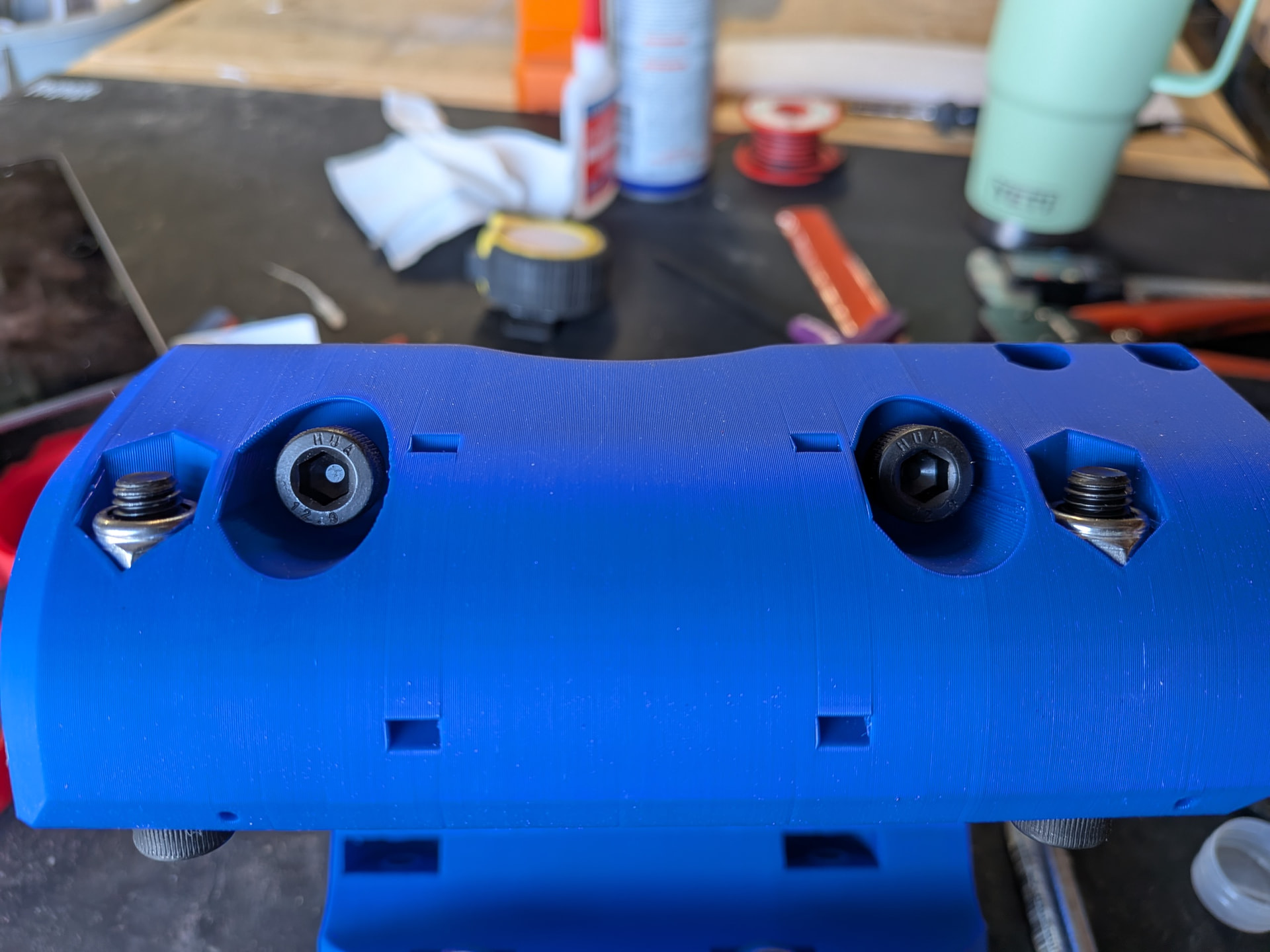
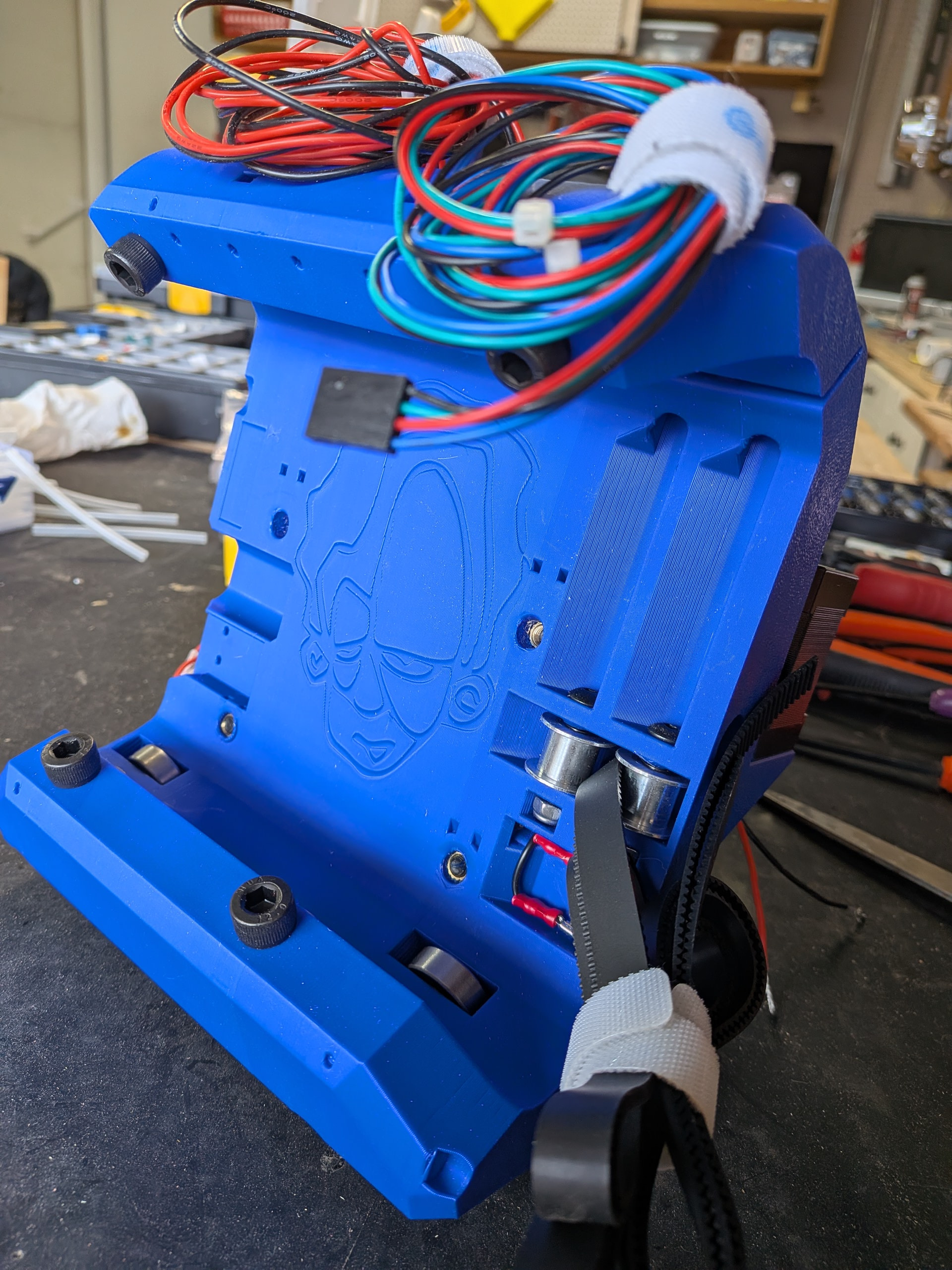
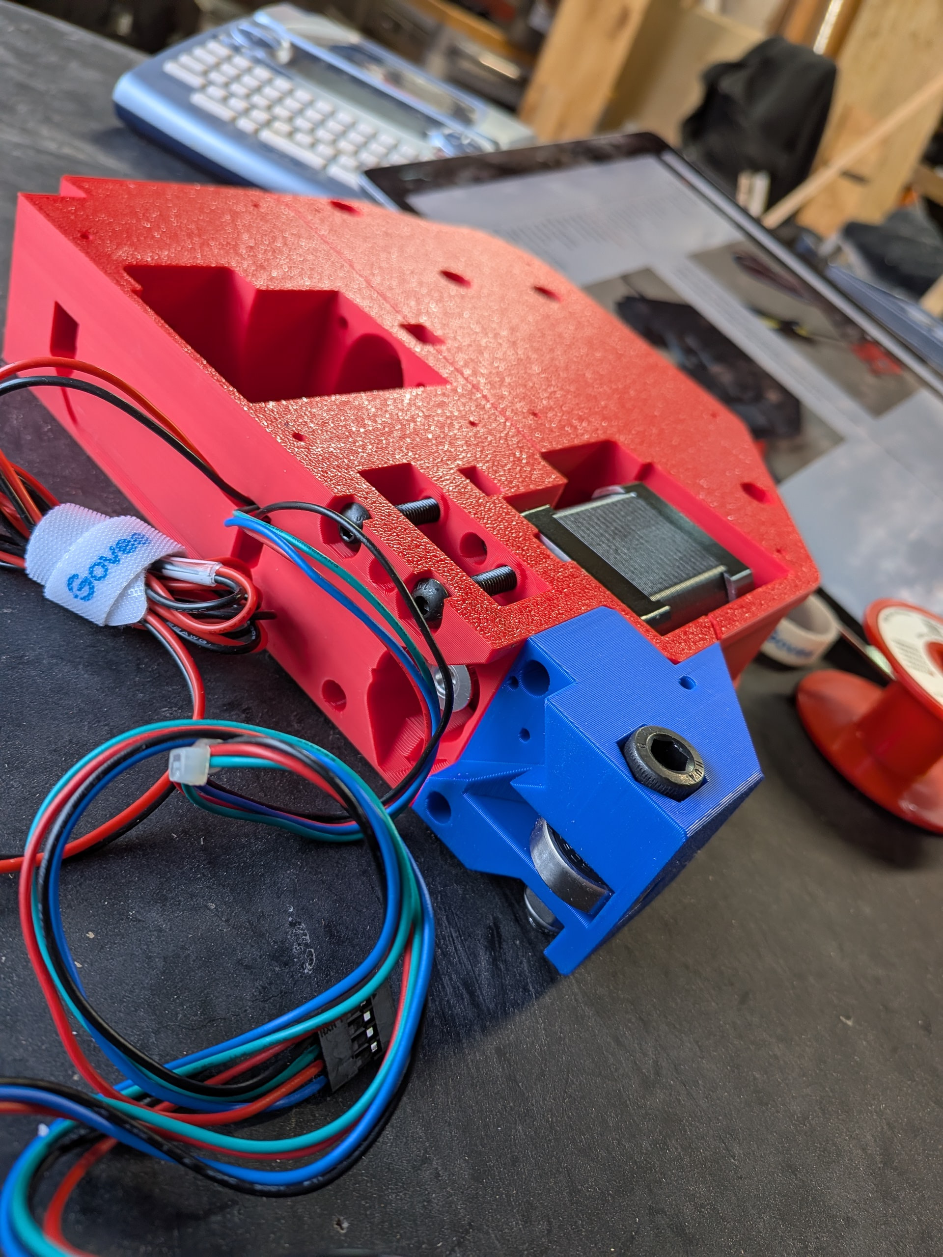
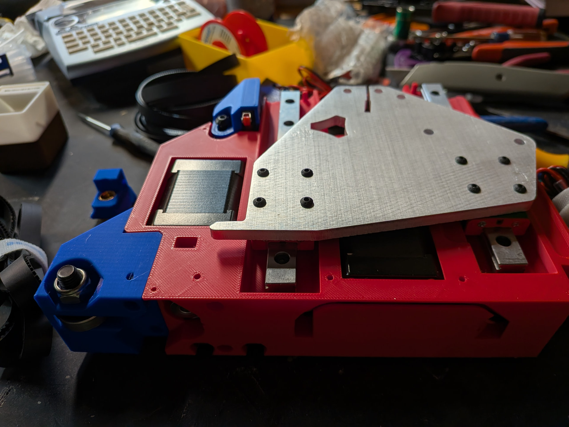
You can see my threaded inserts in the photo above. You will notice, that is why I didn’t have to thread filament in to hold nuts in my core. I was concerned that I wouldn’t get that right. That is one of the things that motivated me to use the threaded insert version.
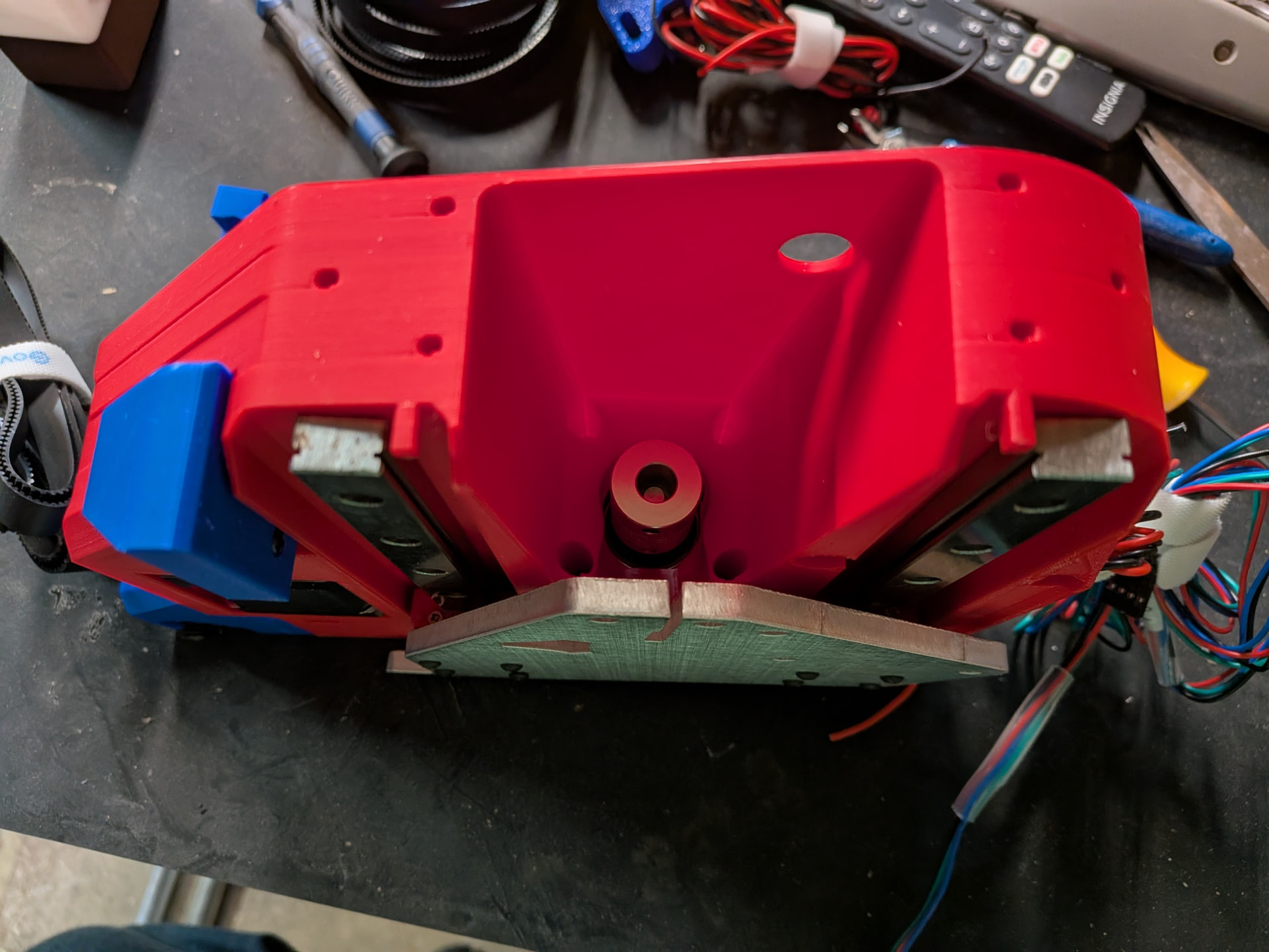
I was sure that I missed a step when I noticed the holes in the core (see below) where it appeared another end stop would fit. Did I miss something or was this for a previous or future iteration?
I was sure the wide connectors for the motors were not going to fit through the tunnels. Not because they were designed poorly but most of the time I follow online directions for a project, including the recommended items to purchase, Amazon has changed versions and the new version is different enough that the original design doesn’t work anymore. Not the case here. They went through perfectly.
Note: The versions I used (selected from the links provided by @vicious1 came with some small zip ties to hold the four wires together. Even these fit through the tunnels with the exception of the final tunnel after the slit. It just got too tight there so I opted to remove the zip ties. They were not necessary at this point anyway.
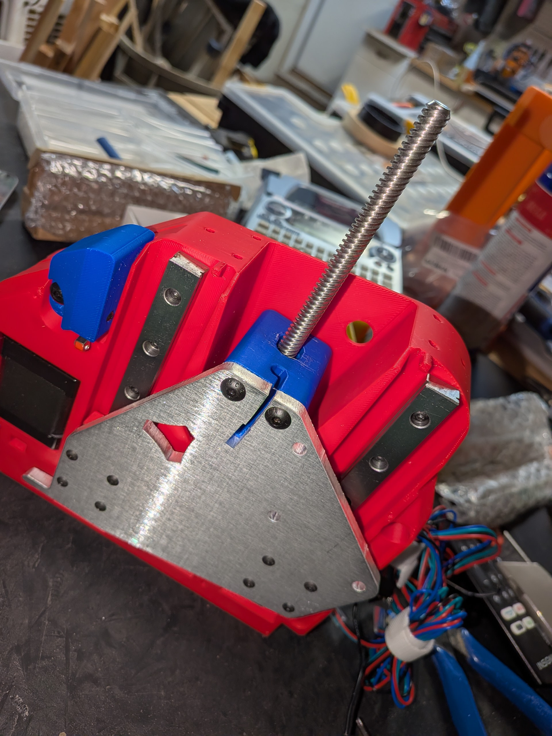
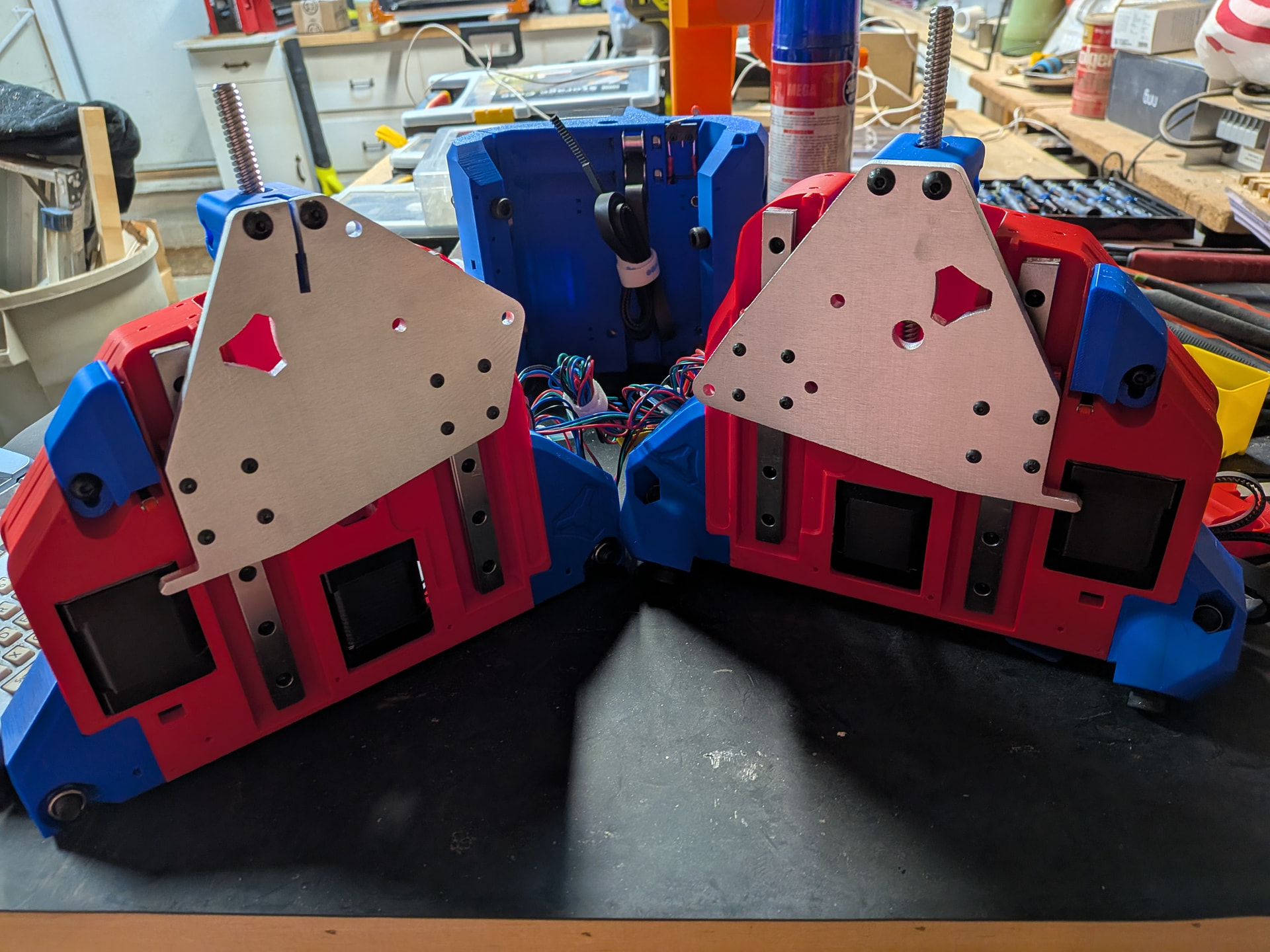
It is at this point that the directions talk about the XZ plate, etc. I was still not oriented enough to know if I was working on the left side of the machine or the right side. The slit at the top of the plate was the most important distinguishing factor.
BTW - The directions suggested clearing out the space where the linear rails go but my Bambu P1S left this perfect so no cleanout was necessary.
It was really not until this point that I could confidently tell which one goes on the right and which one goes on the left. I just did not have the terminology down yet.
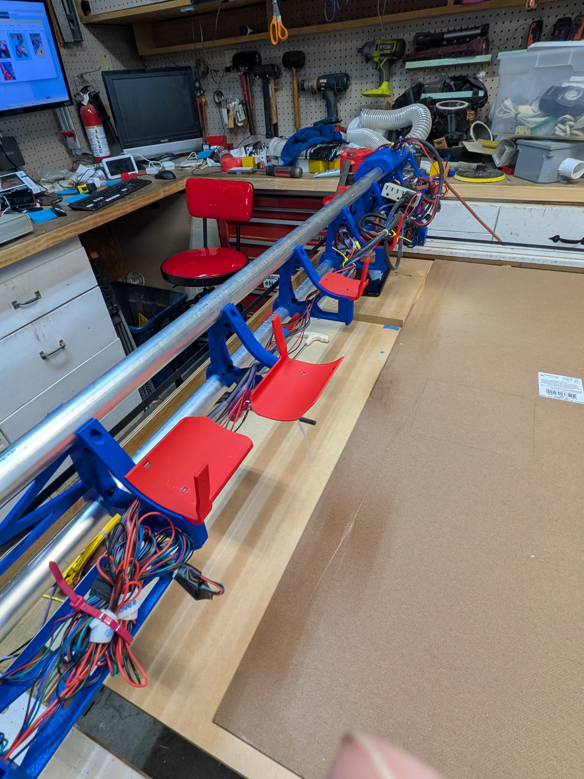
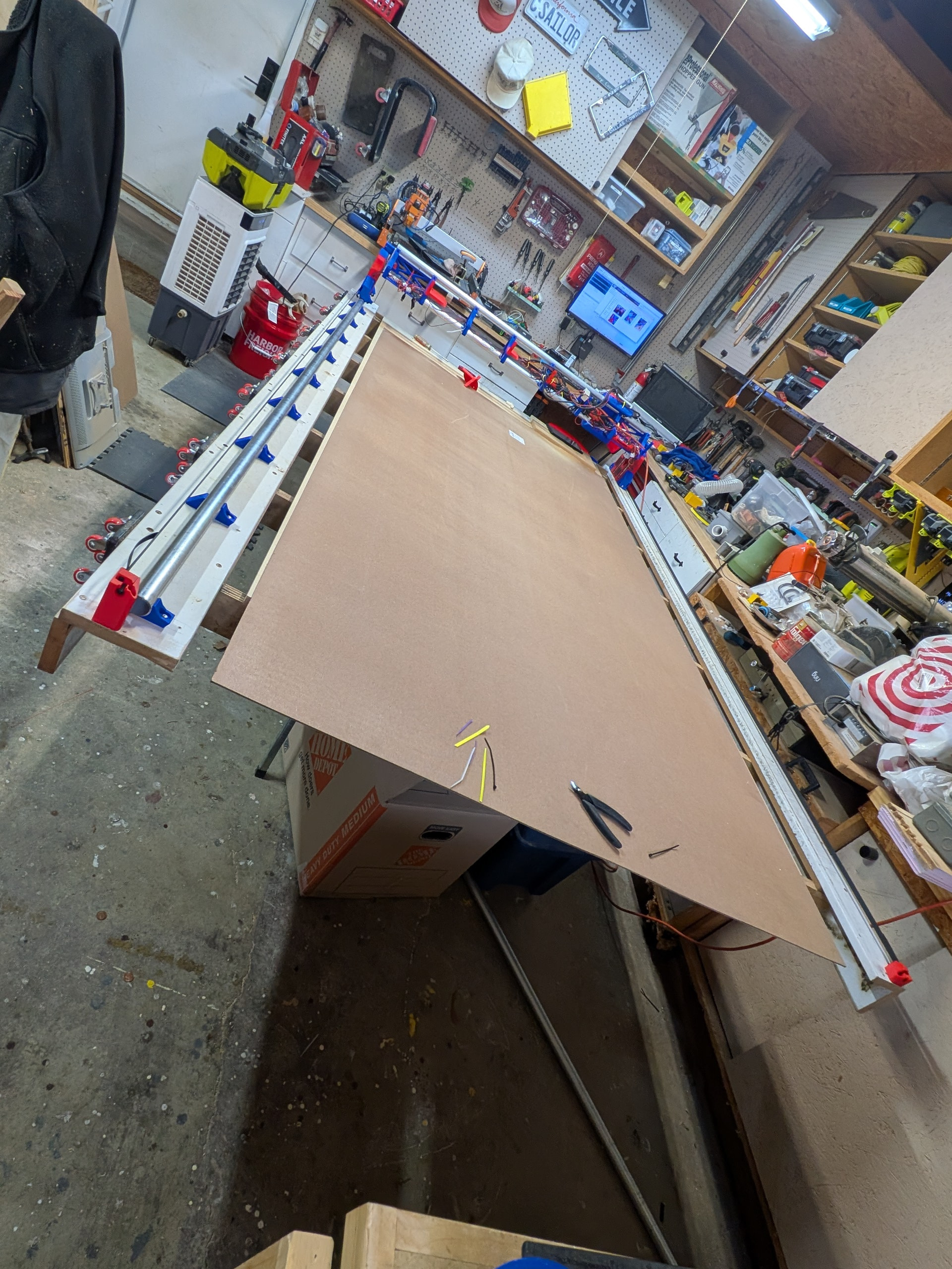
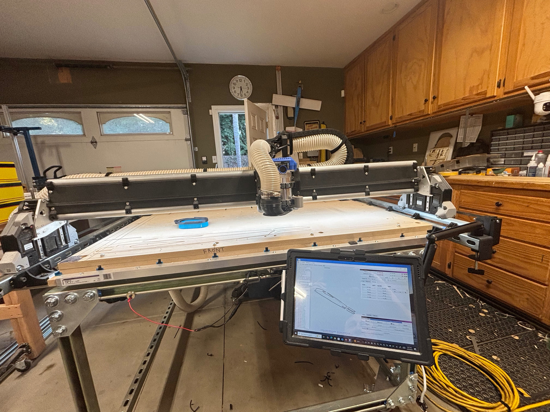
This may be a bit disorienting if you are following along. The top picture is the current orientation of the table (Ymin near my computer). The picture below has the Ymax side closer to the computer. I realized I needed to flip the table around later so I could sit on the stool while running tests, cuts, etc.
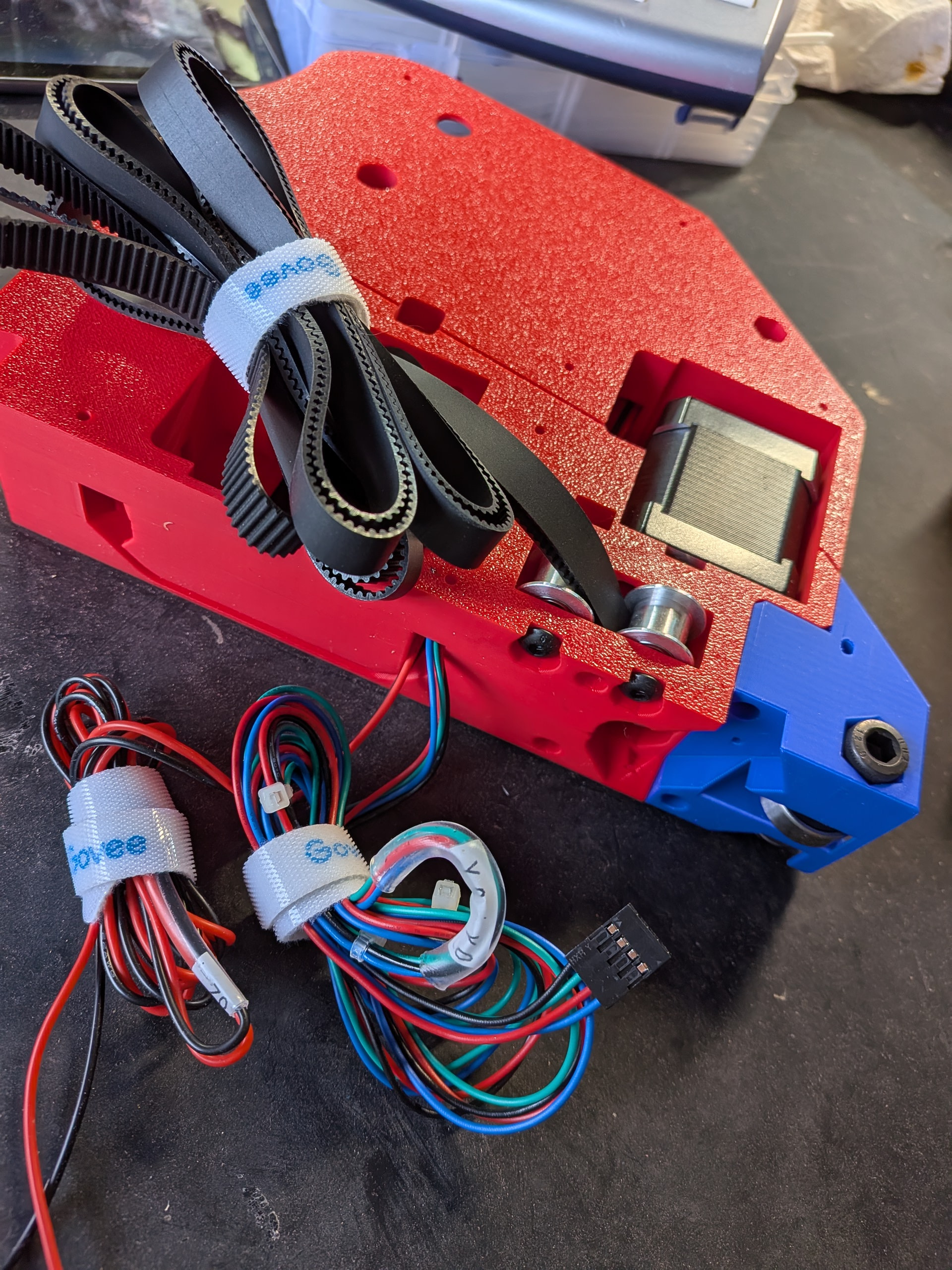
I can’t wait to cut my new struts and clean up the mess of wires. I have some red braided sleeve I plan to use.
I also plan to install the gantry back covers from @DougJoseph . I have not printed these yet because I needed the dimensions from the gantry first. I plan on them being blue.
I did use the wider hose holders from @vicious1 although one project I plan to cut out is an overhead gantry arm for my vacuum hose. I use this area of my garage for all sorts of wood crafts so it would be a great addition.
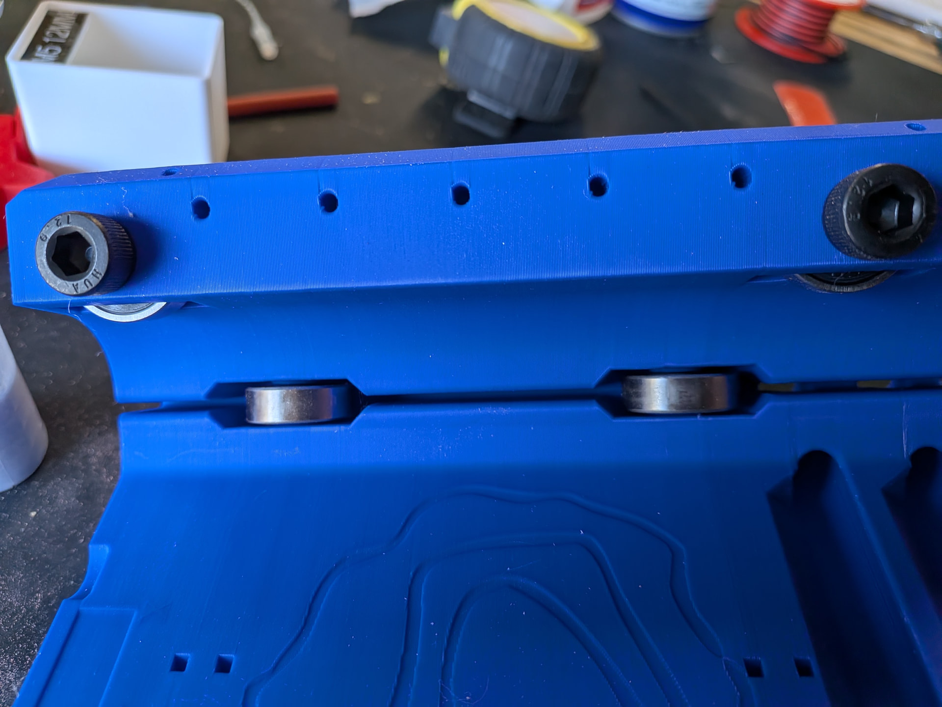
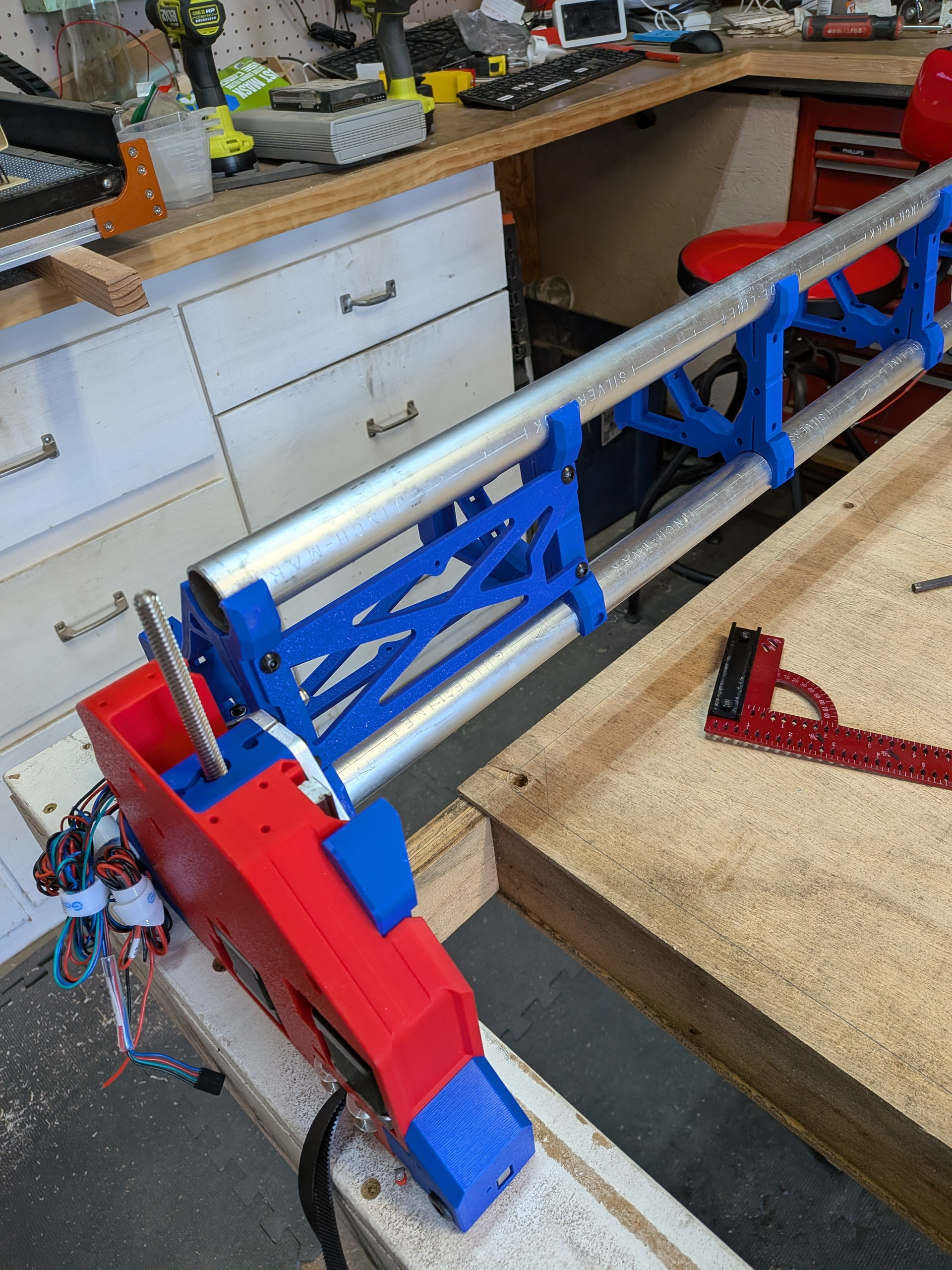
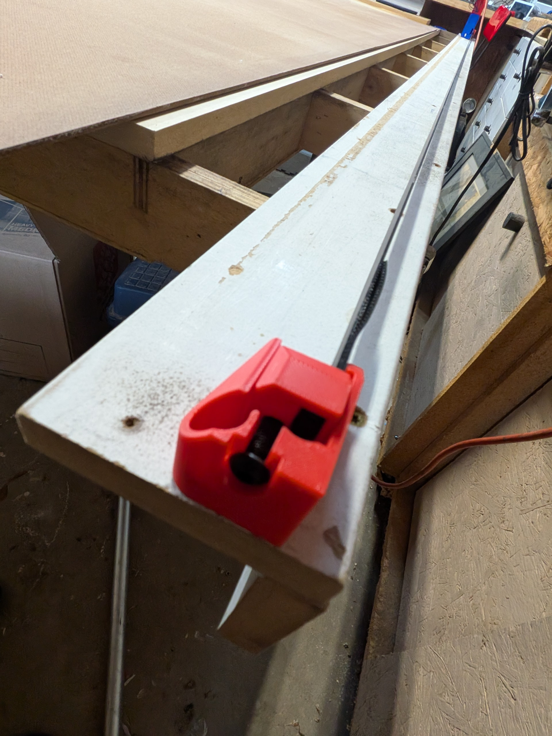
I used the calculator to determine the size to cut the conduit. I went with 56” even. I did this for two reasons. I really want to be able to cut a 49” wide piece of MDF. I also was fortunate to be given a table built by @HyeBuilder . As you can see in the above shot (below), there was a groove worn in the Y track on the min size where the bearings ran. Also, @HyeBuildersuggested on his new metal strut table that he would have gone slightly wider to give himself just a bit more room and not get so close to the end.
You can see I did just as he suggested. One suggestion I did not implement was replacing the mdf Y platforms with metal unistrut. I really like this idea but I kept hearing the advice from many on this forum to stick to the Yellow Brick Road. This may come later but I restrained myself at this point.
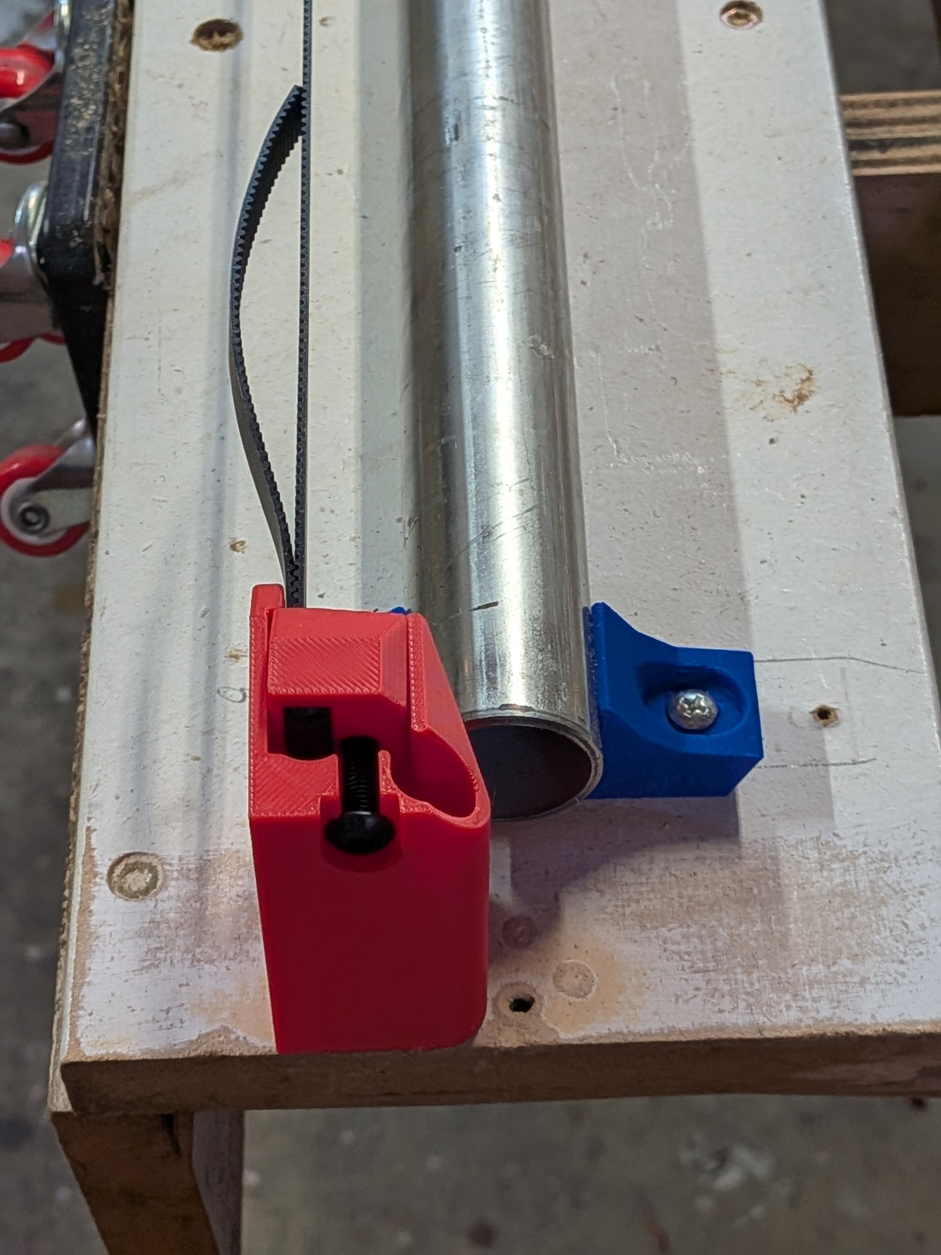
Now I needed to mount the Y tube/rail/thing. I left it full length originally so I could make sure I knew how long to cut it. I have the table and used the calculator but I convinced myself I was doing high end reserve math matching the machine to the table rather than the table to the machine. It was probably a bit silly on my part but it worked out.
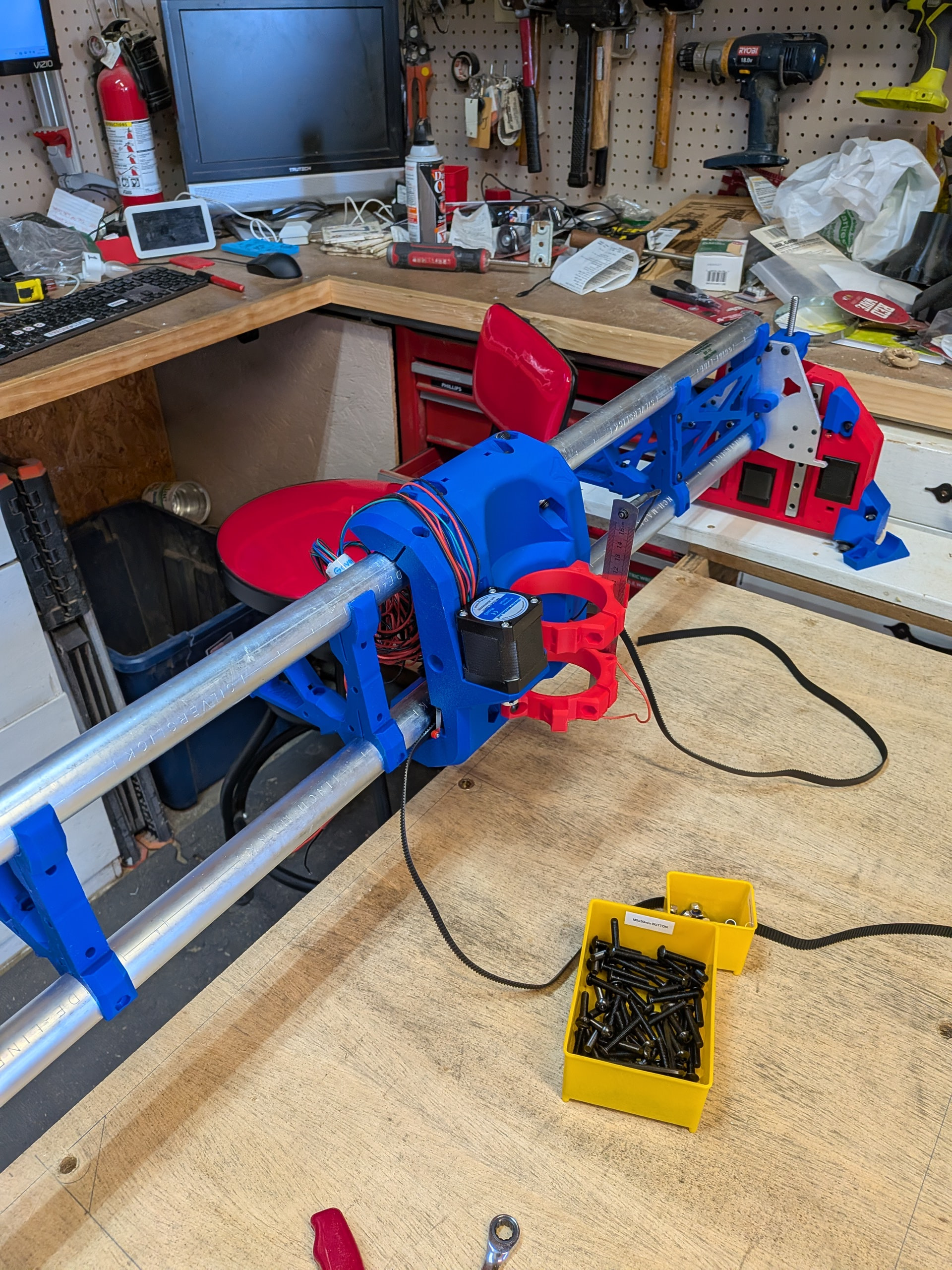
Here it is. The YMax is closest in this shot. It has a piece of 3/4” mdf spoil board on it and then a piece of hardboard that I plan to cut the struts out of.
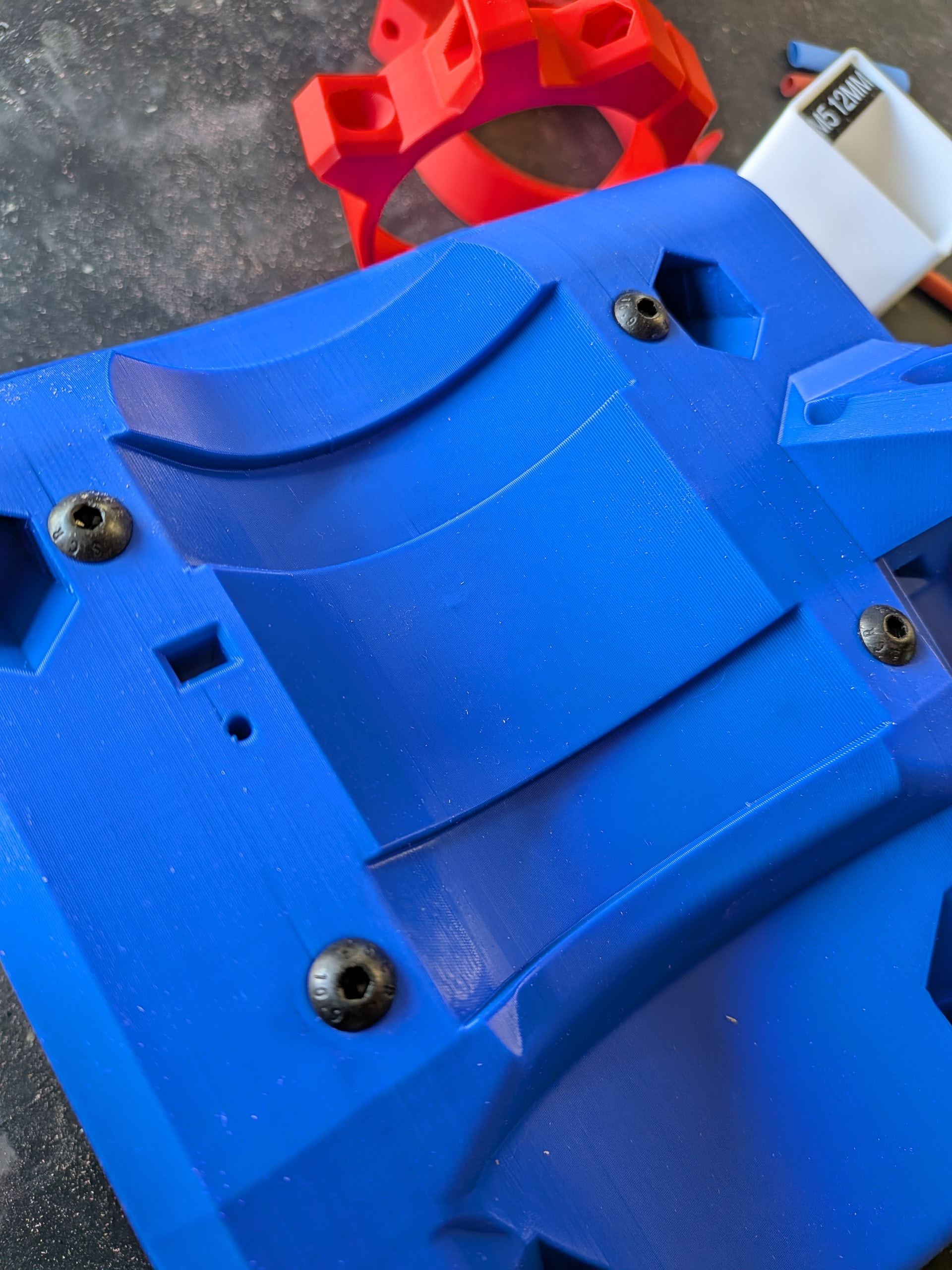
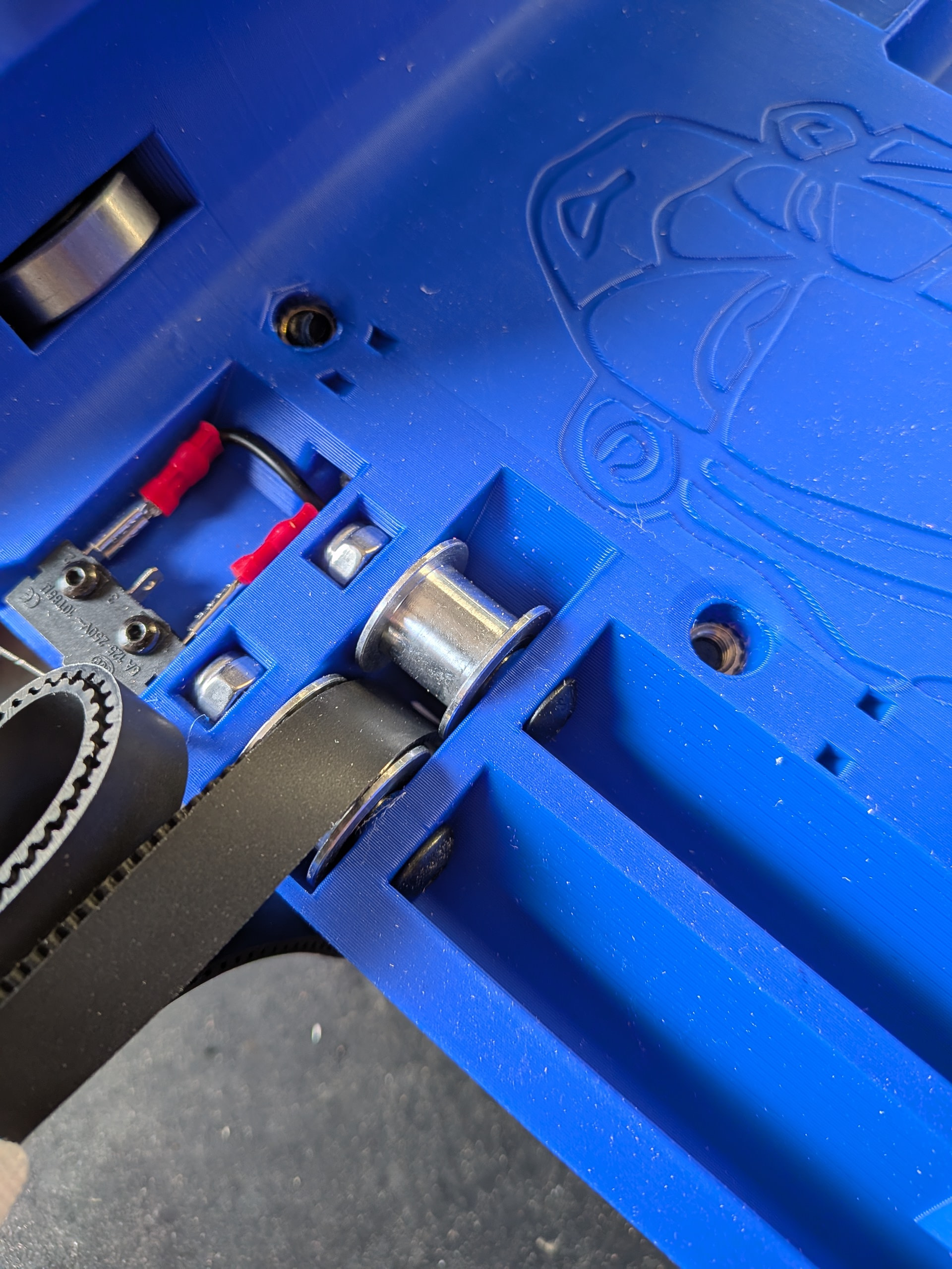
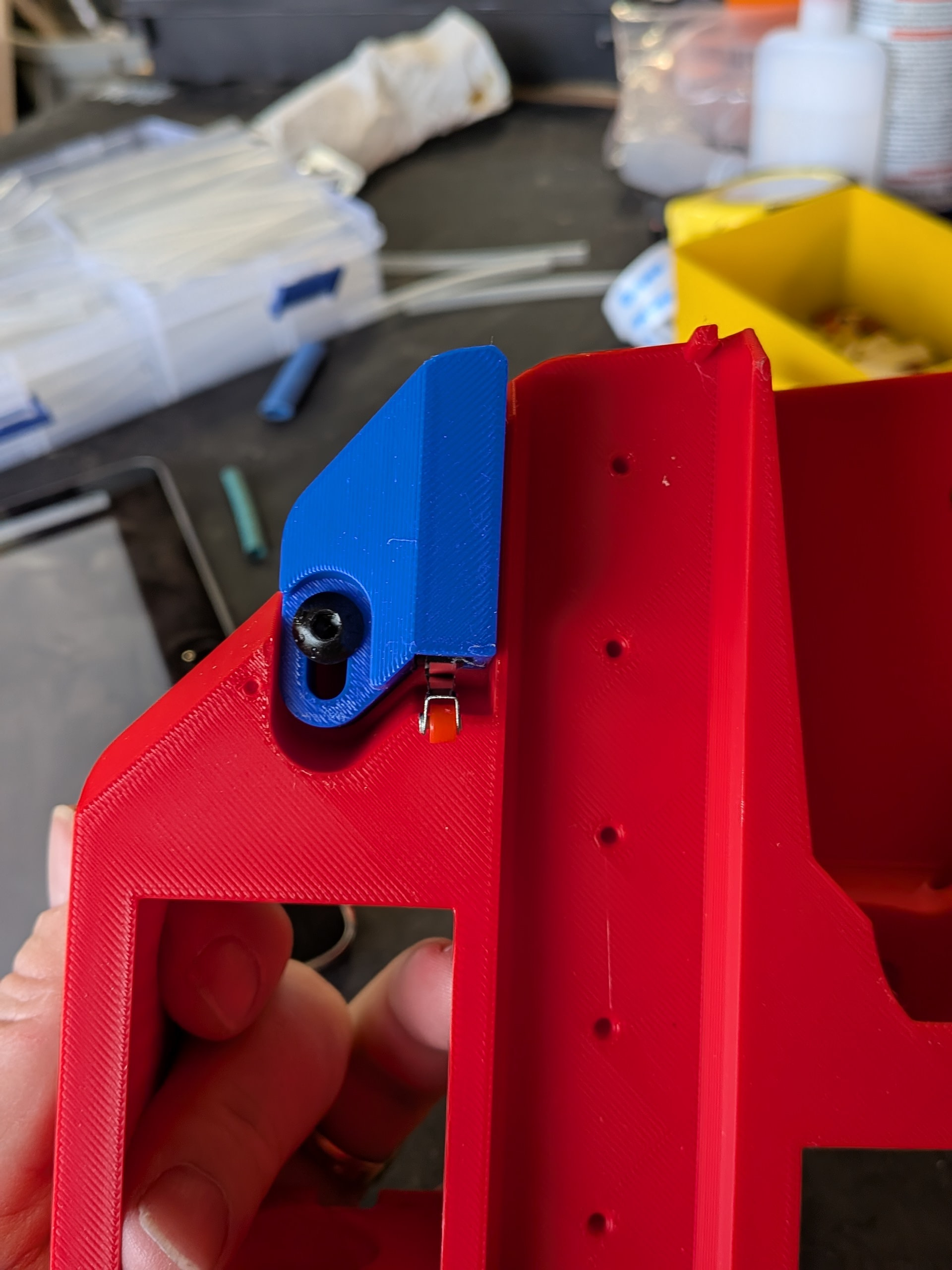
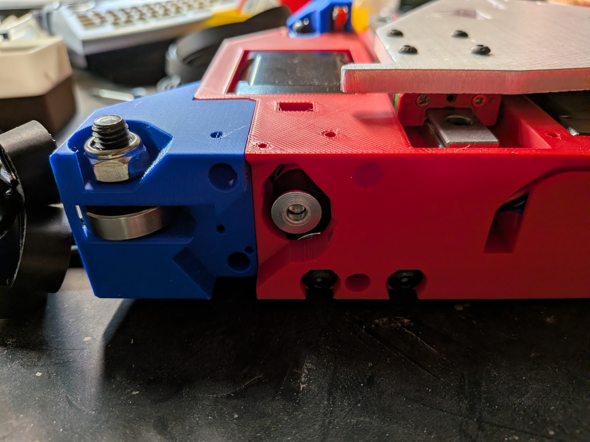
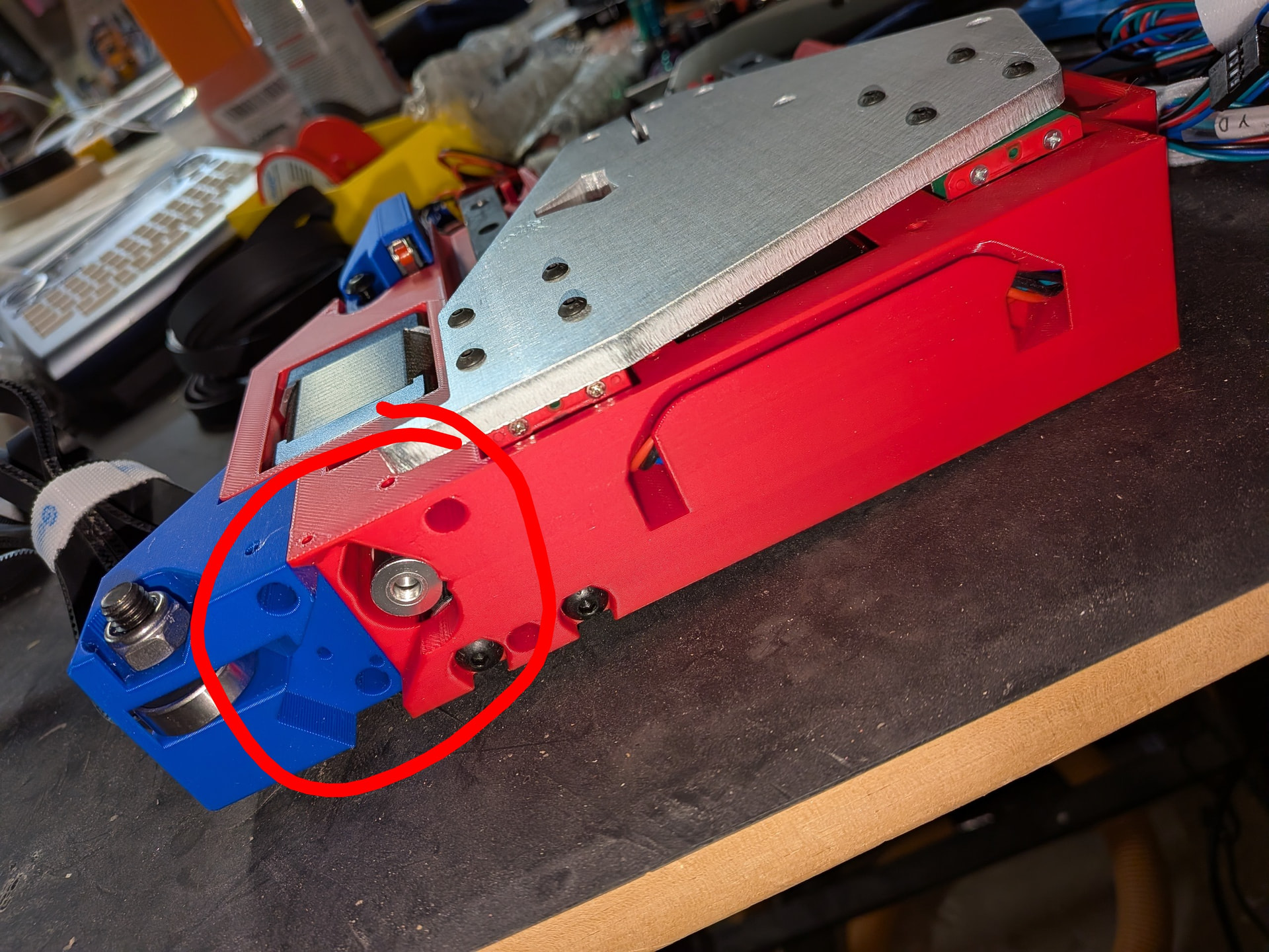
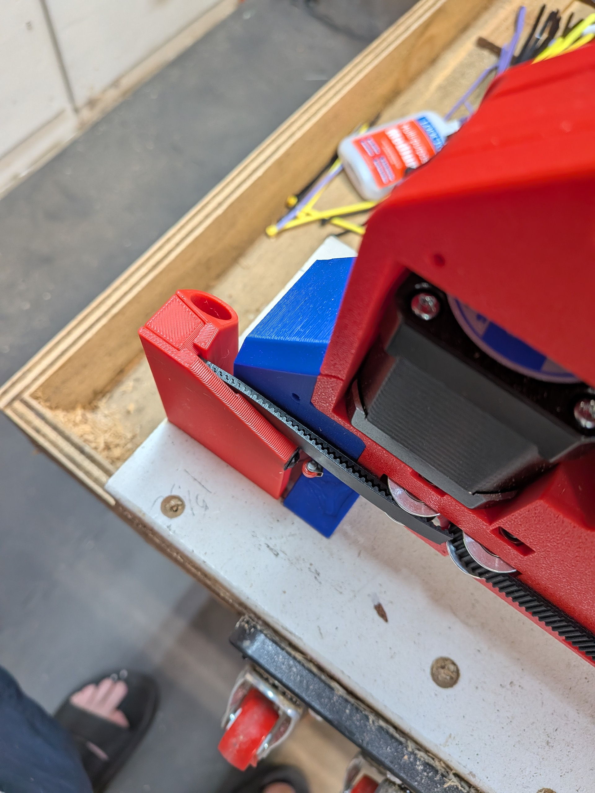
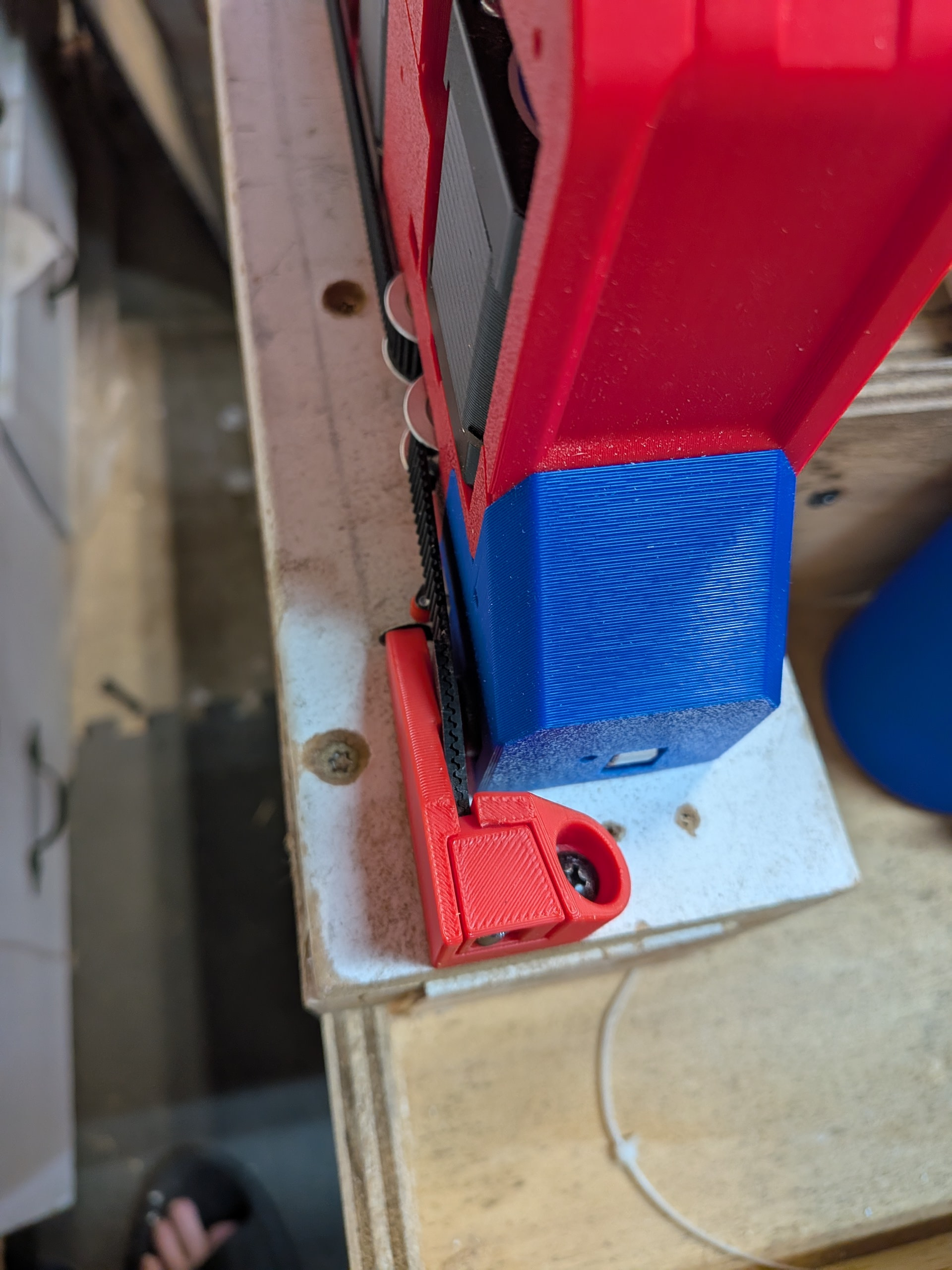
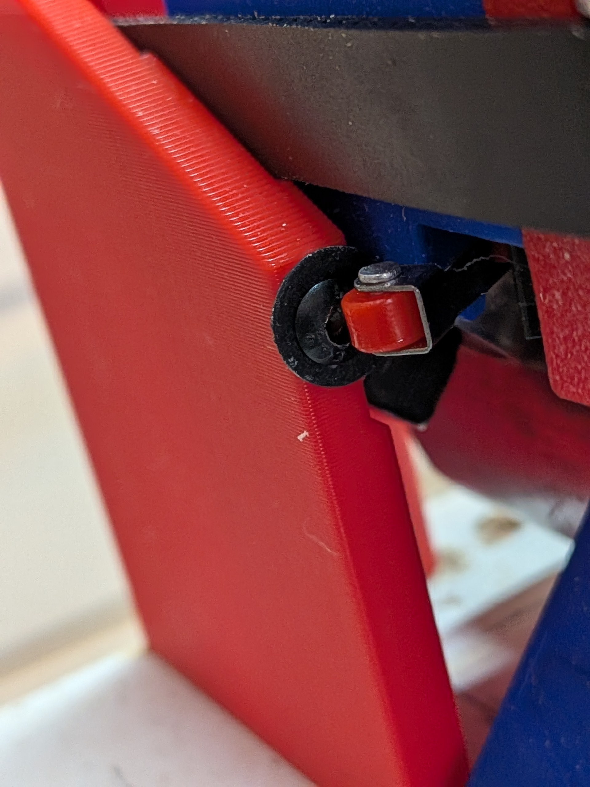
This is the Ymin/Xmin side (below). I have been running into issues with the endstop missing the screw. I think the gap is a bit too wide between the YZ tower and the belt holder. Often I find this side rides a bit toward the Xmax side and slips past the screw to trigger the endstop.
I can adjust it later but for the time being I added a couple washers to the screws to give a bigger target for the enstop to hit. I am thinking about using this one.
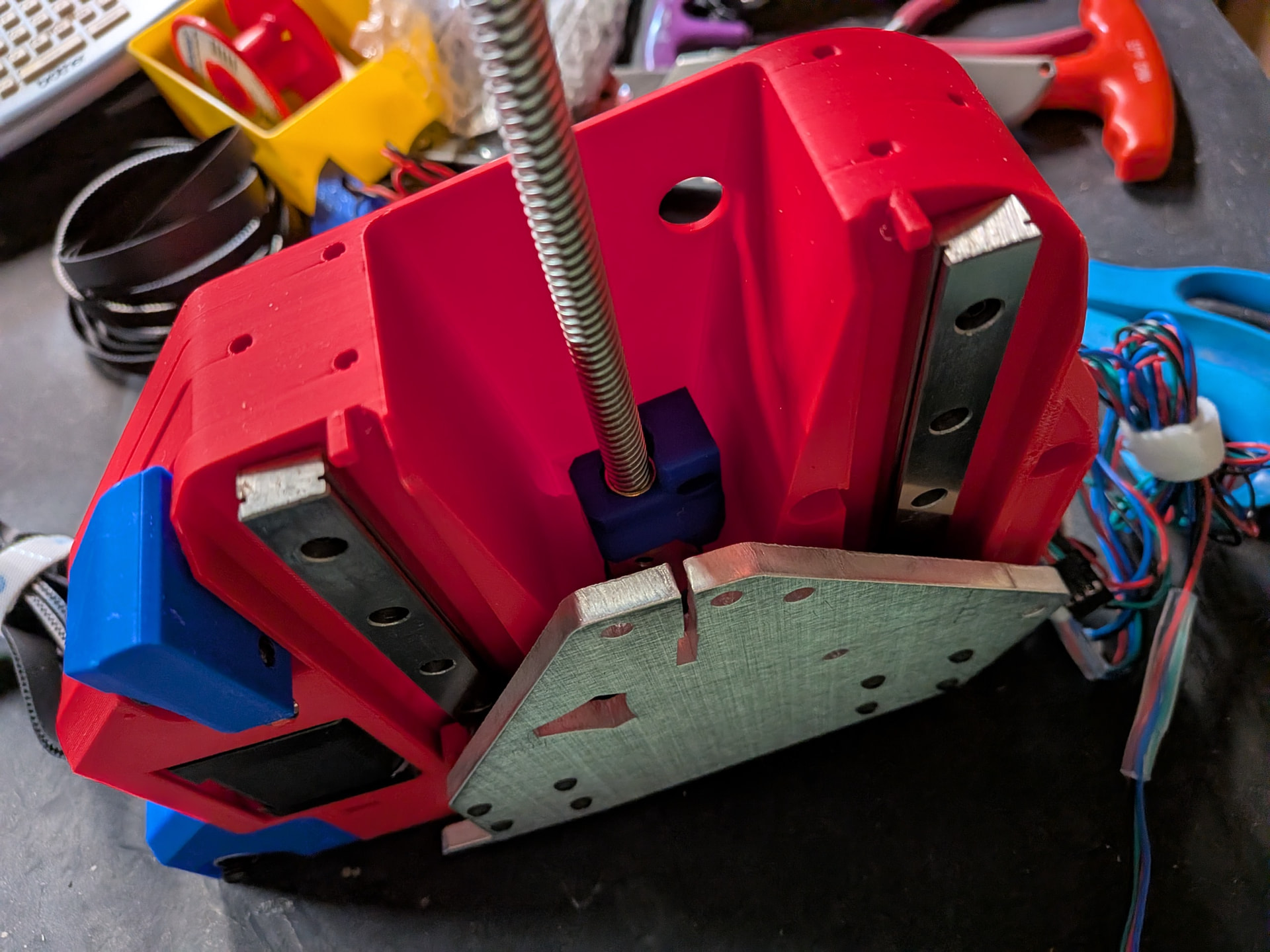
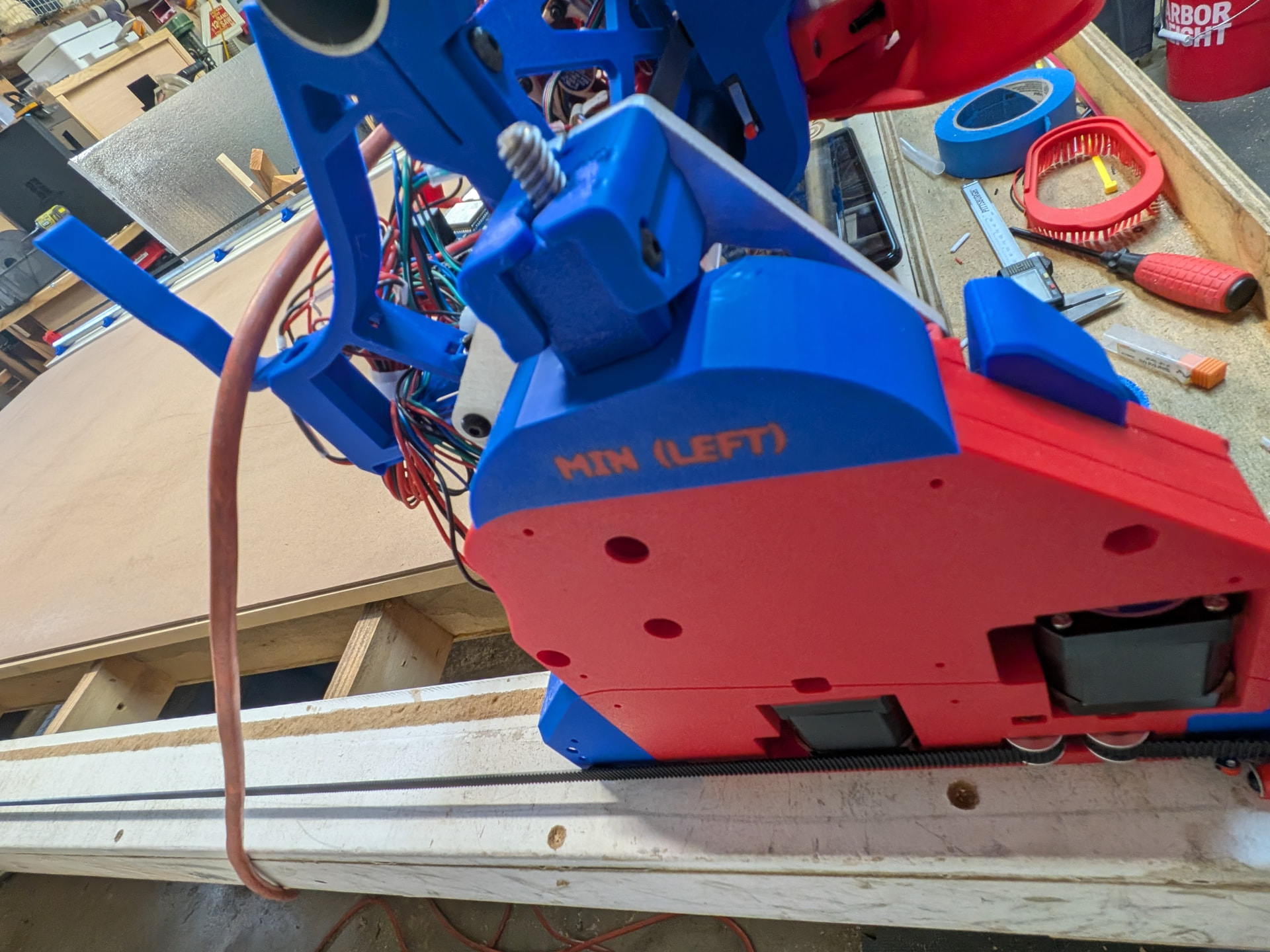
Now I added a couple of Z blocks for times when it is powered down.
I am concerned posting these photos because I still lack confidence regarding min and max, etc. Having run the machine around a bit I feel better since Y+ goes away from me and X+ heads toward the rail side, etc. I think I am getting it. Feel free to correct me if necessary.
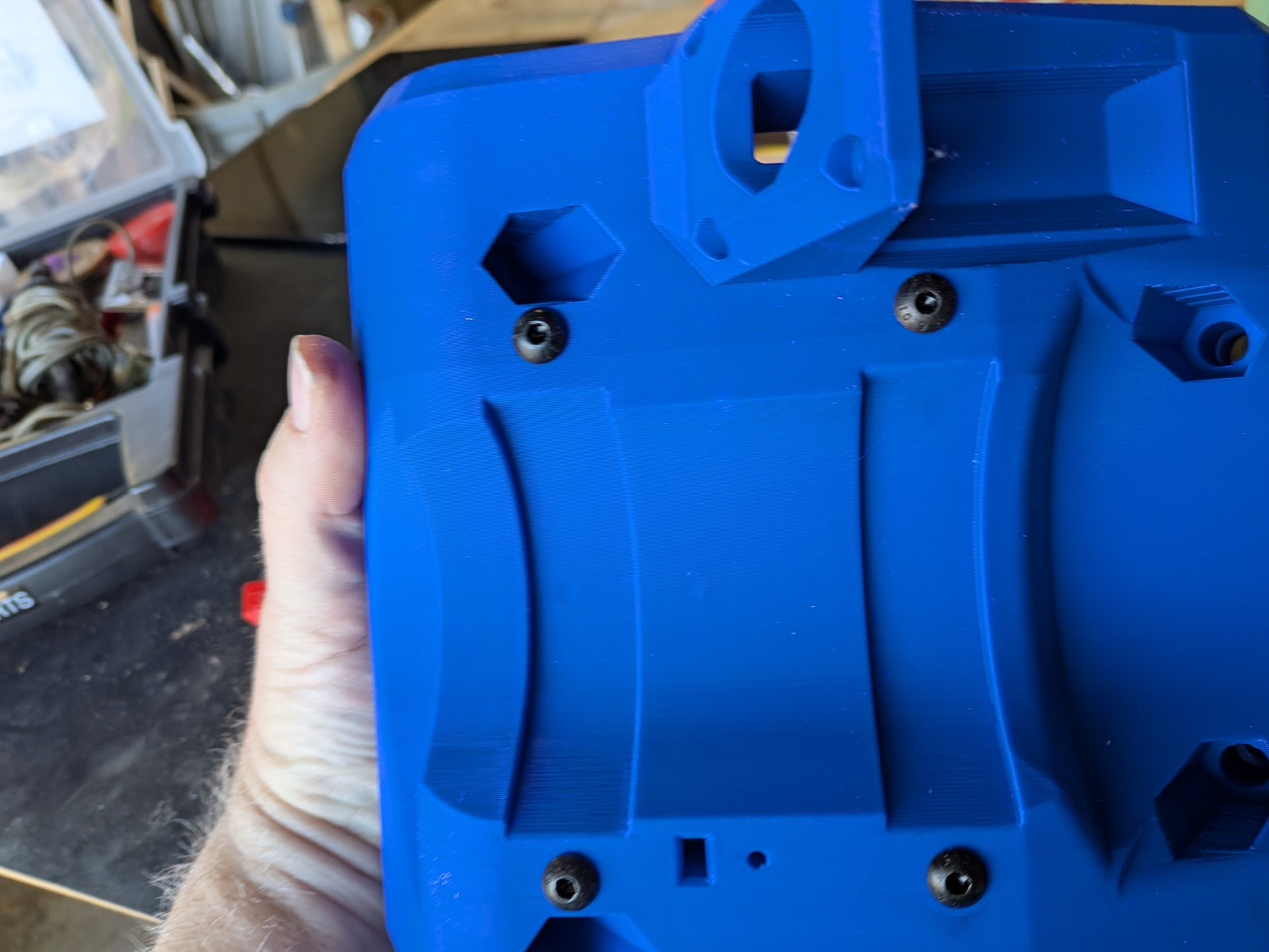
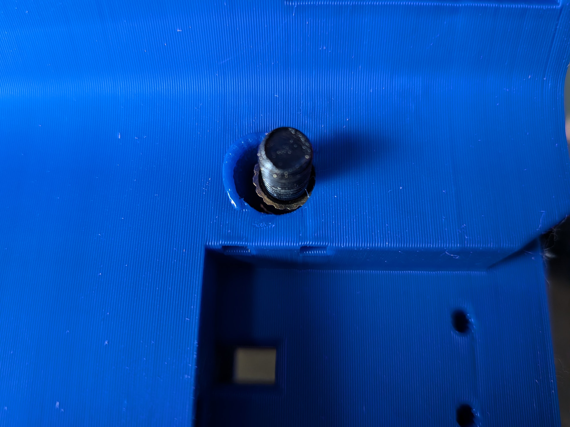
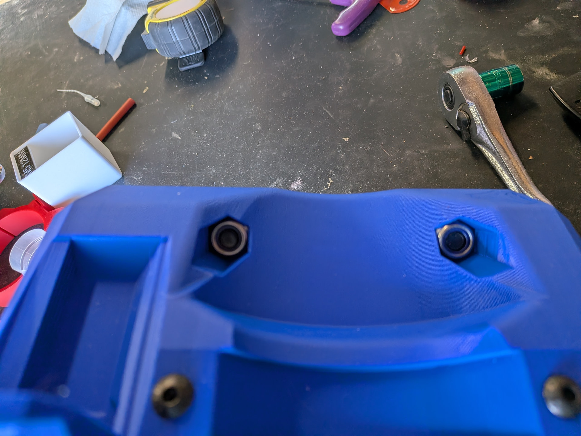
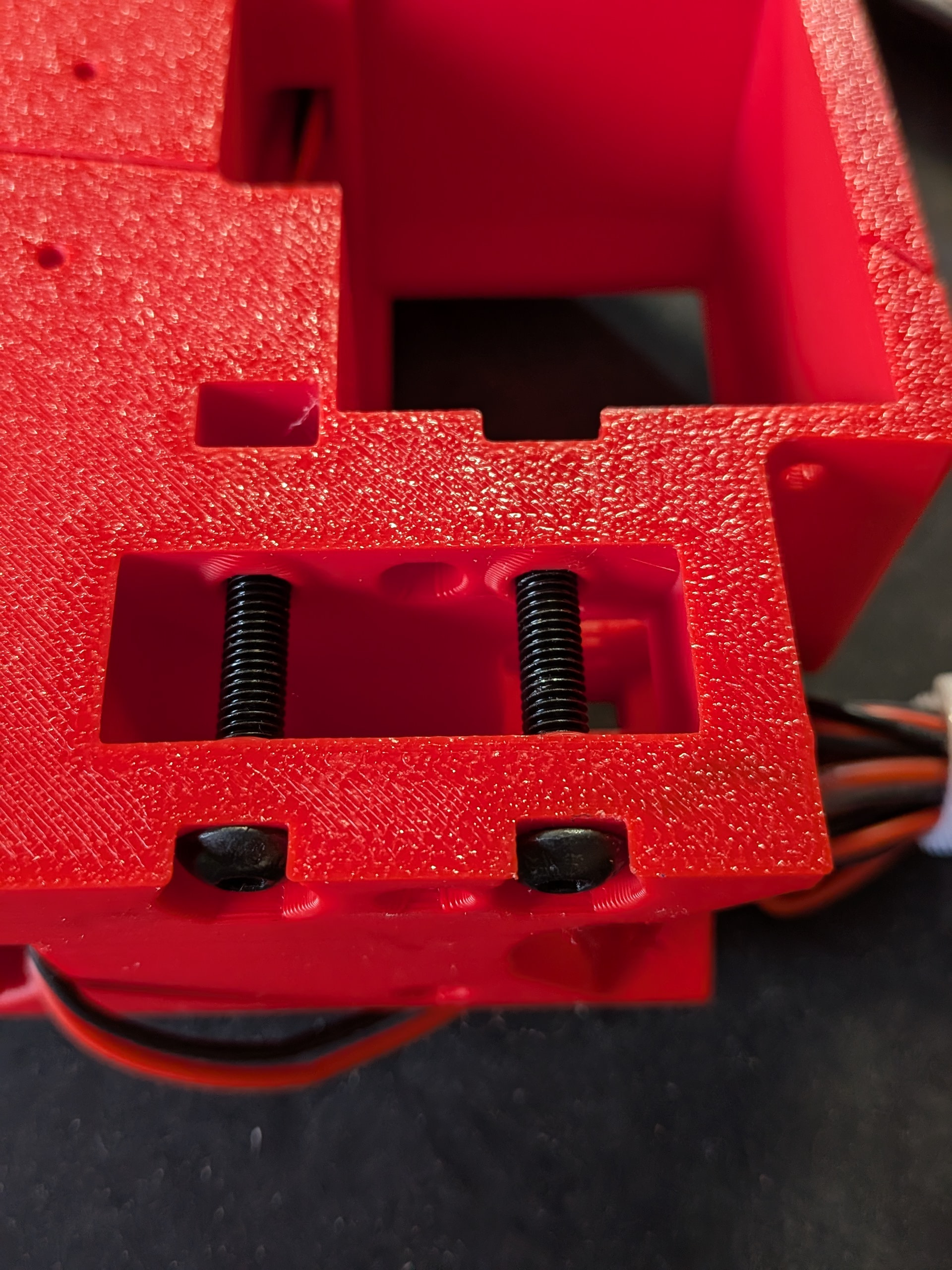
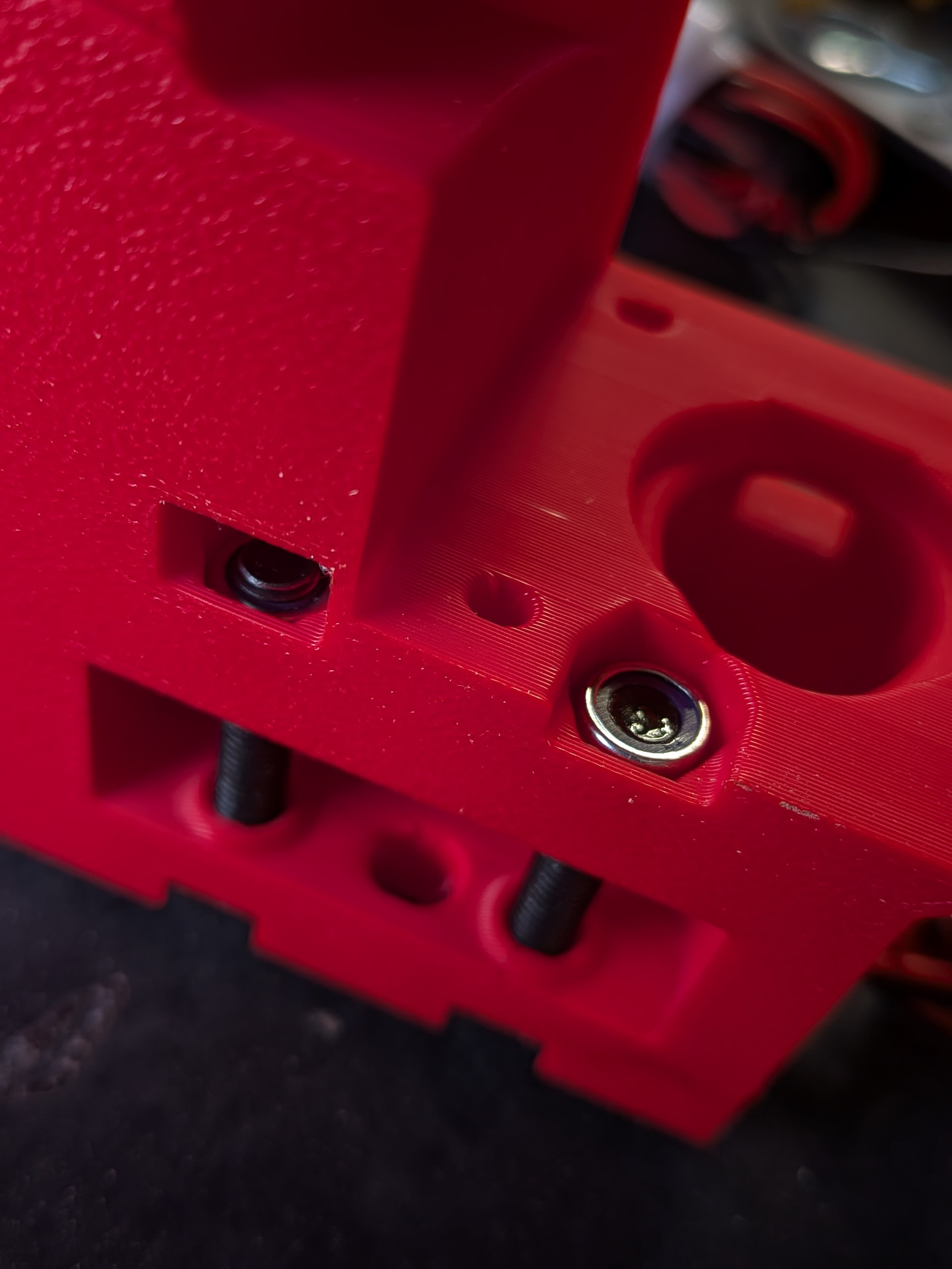
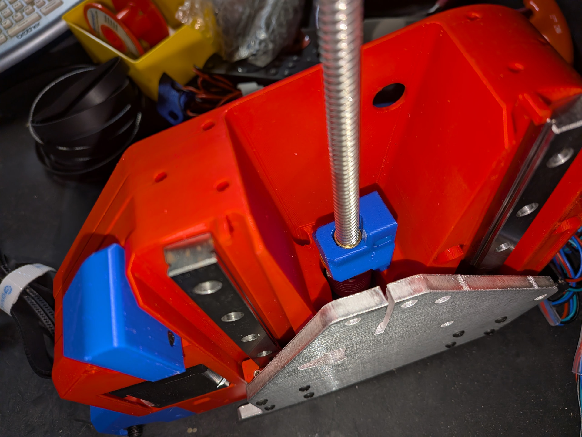
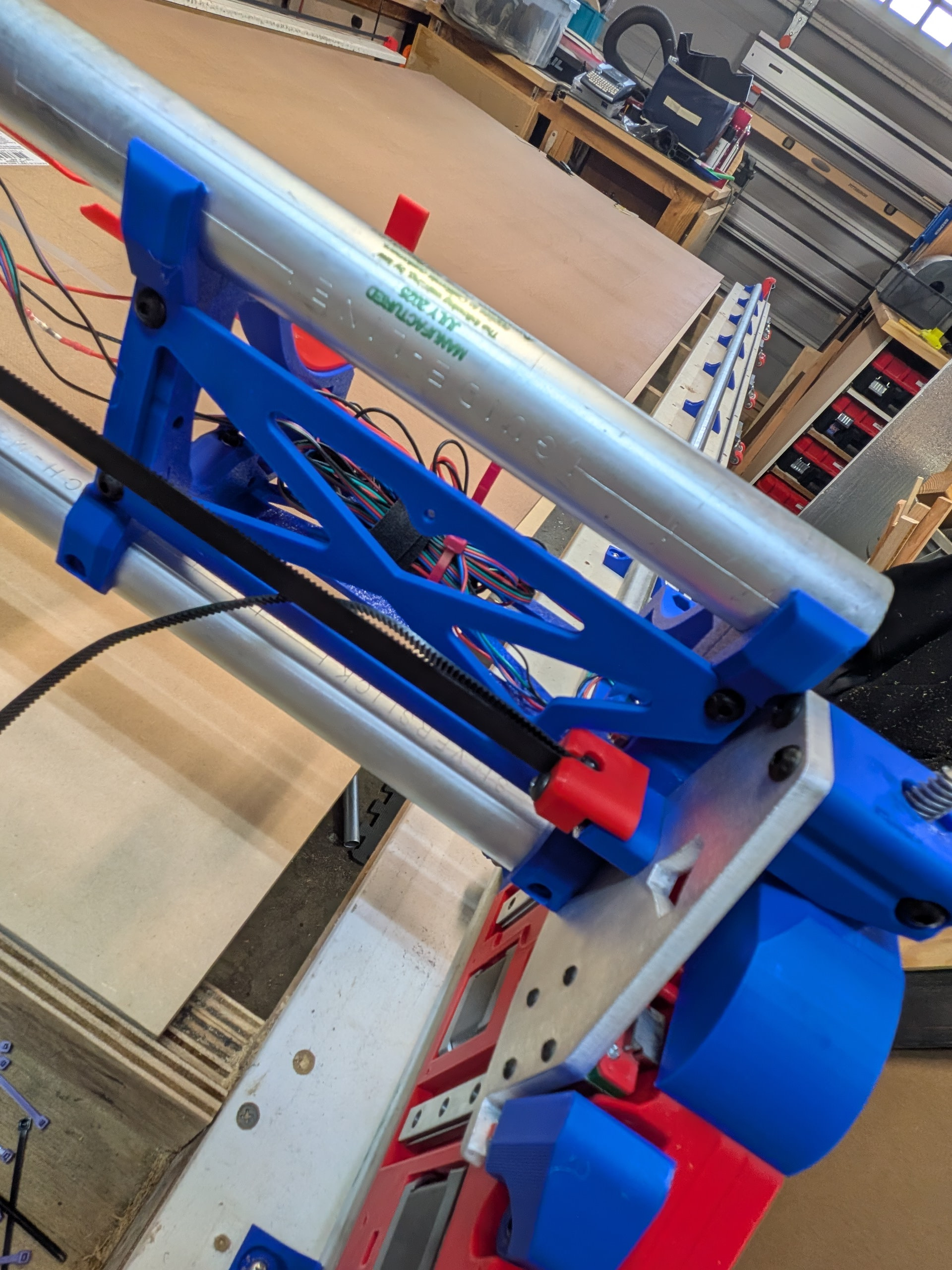
Also, you will notice the bolts through the Z stub and the Z-nut. This appears to be controversial and unnecessary (based on threads on this forum) but I got tired of having to reach in and spin the Z-nut back up into the Z-stub when it would fall out. I watched a video suggesting that the Z-nut should fit semi-snuggly in the Z-stub but mine is pretty loose.
I originally ran a zip tie through the stub/nut hole but realized it might interfere with the Z-travel. Instead I placed the bolt and nut through but did not tighten it at all. It simply is keeping the two parts together. Z seems to be working well so I think it is working.
That is as far as I have gotten thus far. I was able to make some cuts. It was fun (until I started having problems with X. More on that in the troubleshooting forum.
Find a design for a “control panel” featuring an emergency stop, on/off switch, vacuum on/off, lights on/off
Install LED COB lights (one last off road adventure) using @DougJoseph clips
Run vacuum hose
Initial Calibrations
Install and surface the spoilboard
Using the * * threaded inserts and nylon bolts similar to those originally used on this table by @HyeBuilder This will hold the spoilboard but I need some additional stock holding options. I mostly used CA glue with tape on my Foxalien but I don’t see that as a good option when I am wanting to cut larger pieces.
Switch from an AP connection to a STA connection.
I have been messing around with Millmage. It is really easy and I am very familiar having used Lightburn with my laser but having my desktop hooked up to AP prevents me from having internet access and I need that to continue working on the computer when the job is being cut or while designing the jobs. Also, it doesn’t seem to have a soft reset. Perhaps it is one of the macro buttons but, if so, it is not real clear.
Note - I went off-road and tried to switch this earlier this week but ended up so far off the Yellow Brick Road that I was not sure I could make it back. Gemini was helping me navigate and I almost had to reload the firmware. Fortunately it all started playing nice again.
Looking good Scott. When you go to do the lights under the gantry, when I rebuilt mine for the strut table, I used 24v lights and wired them to come on when powering up the jackpot (split before jackpot of course).
Orientation look fine (as far as I can tell… but I don’t proclaim to know much beyond the ability to read directions. LOL).
Millmage. I really like it .. so far.
To address the internet connection thing, I picked up a refurbished surface pro tablet from amazon and it connects directly jackpots wifi. Just before doing that I connect to my wifi and make sure I can access the project files stored on my cloud drive.. these I made at the desktop. Took a bit to dial in the software to store and save setup, settings, libraries and project files on the cloud…so whenever I first up MM, it knows where to look for all that in the same place regardless which computer I use. Once I have the access and open the job, i then connect the tablet to the jackpot wifi directly and run the job. The tablet is not used for anything else other than running the job… making a few minor adjustments, etc. I think I paid like $150 or $200 for it.. and I just recently added a mount for it.
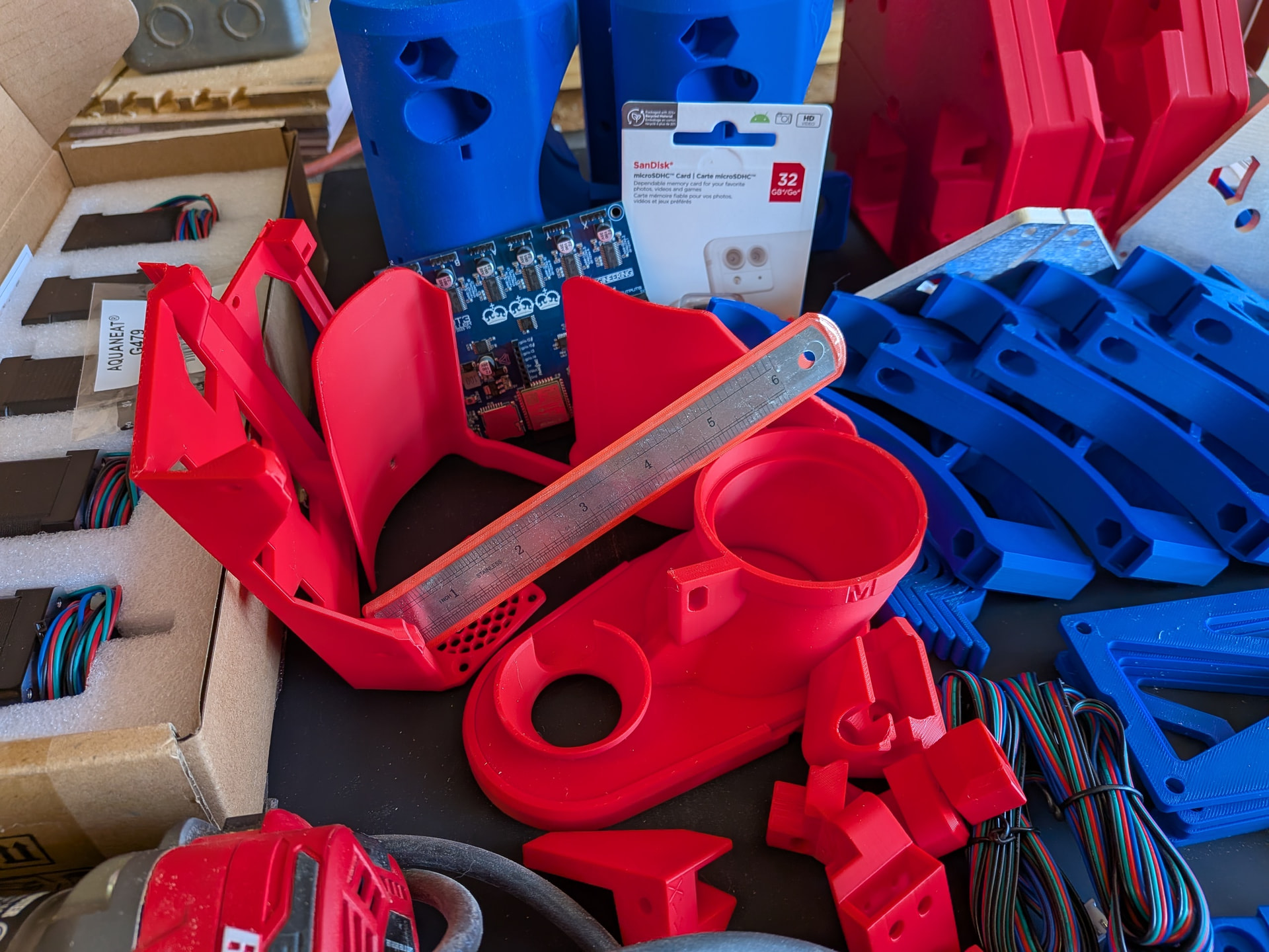
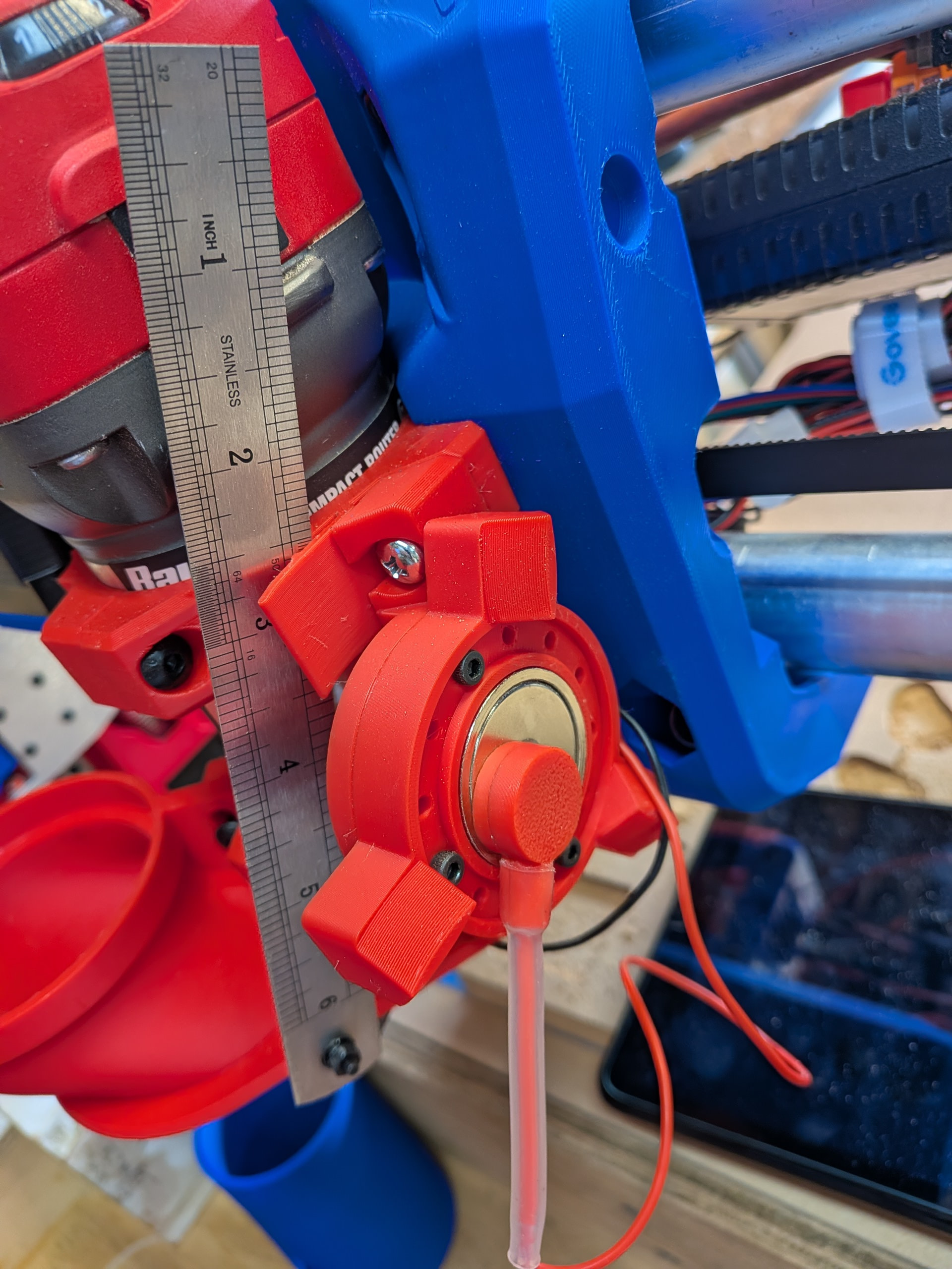
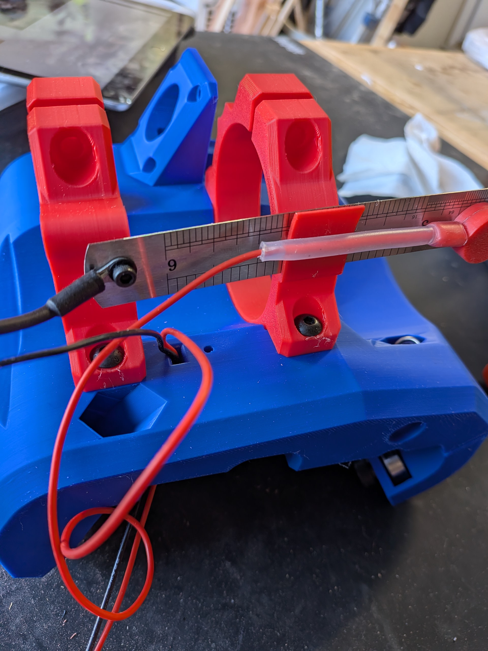
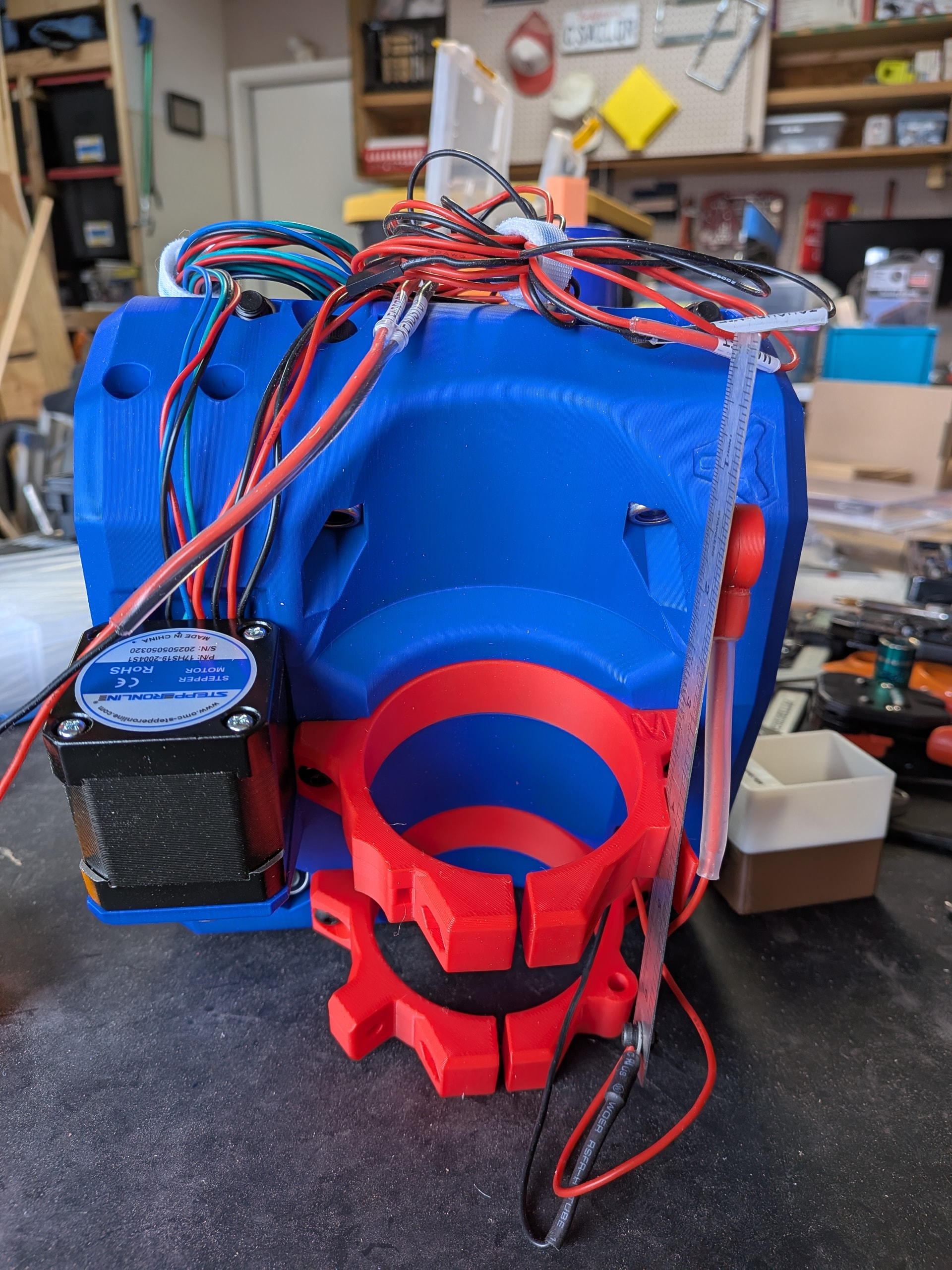
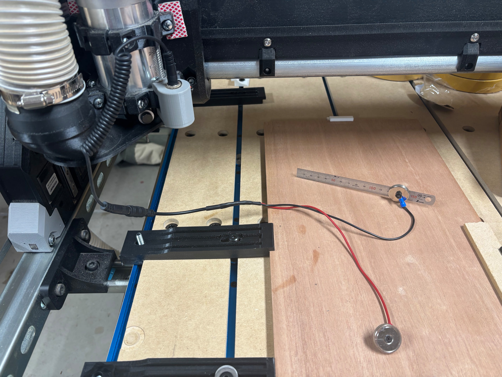
I ended up getting a steel ruler (mm) that was .5mm or whatever the thickness was of the original probe from Ryan and used magnets on both ends of the wires… one on the ruler and the other on the bit… I also made a mount so I can use barrel plug to disconnect the wire when probed so it is not in my way.
Spoiler - it was a bad connection between the X stepper motor and the extension - even when using the “S” strain technique. (I guess you have to make an X AND make sure the connection is together. )